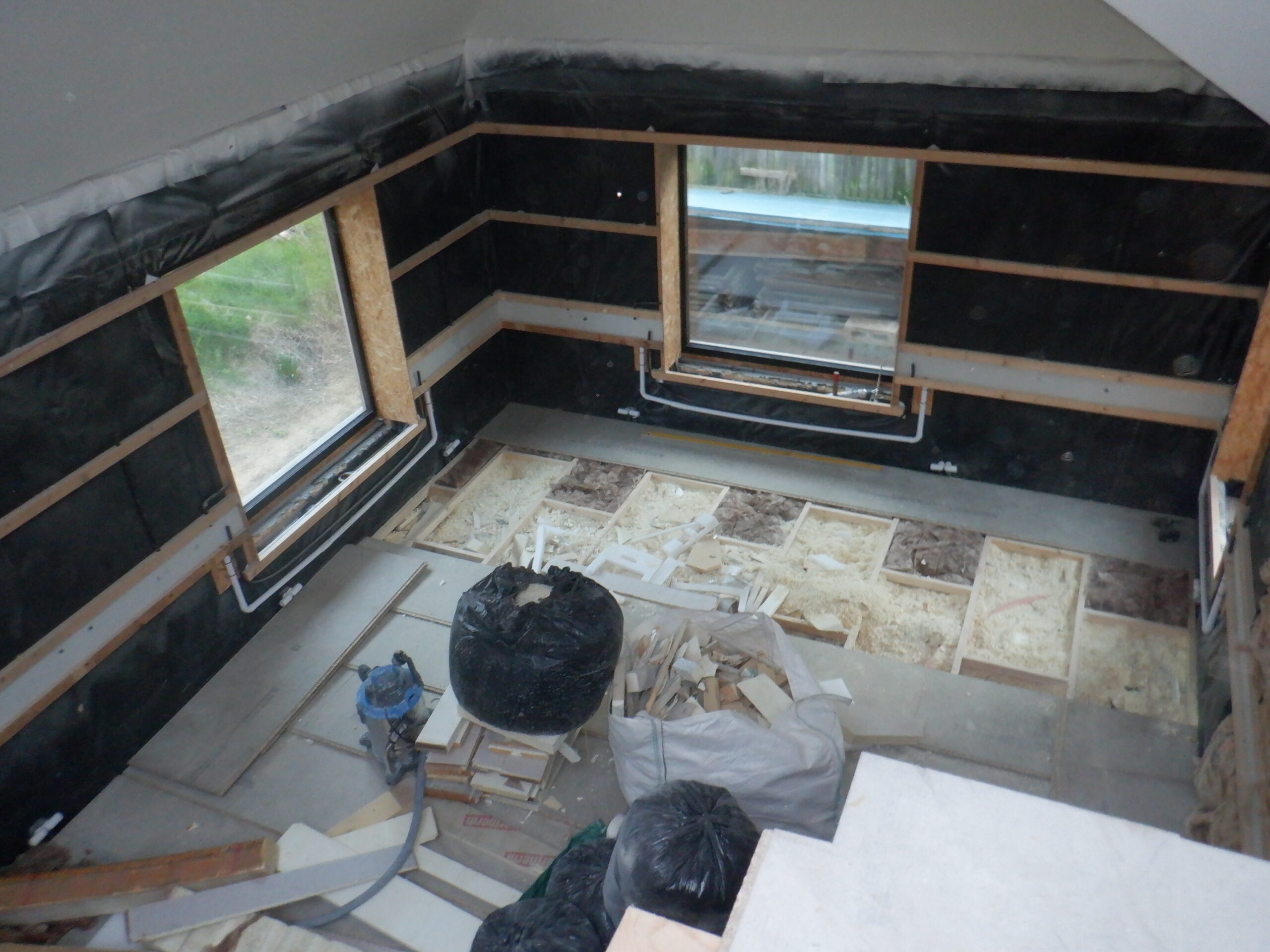
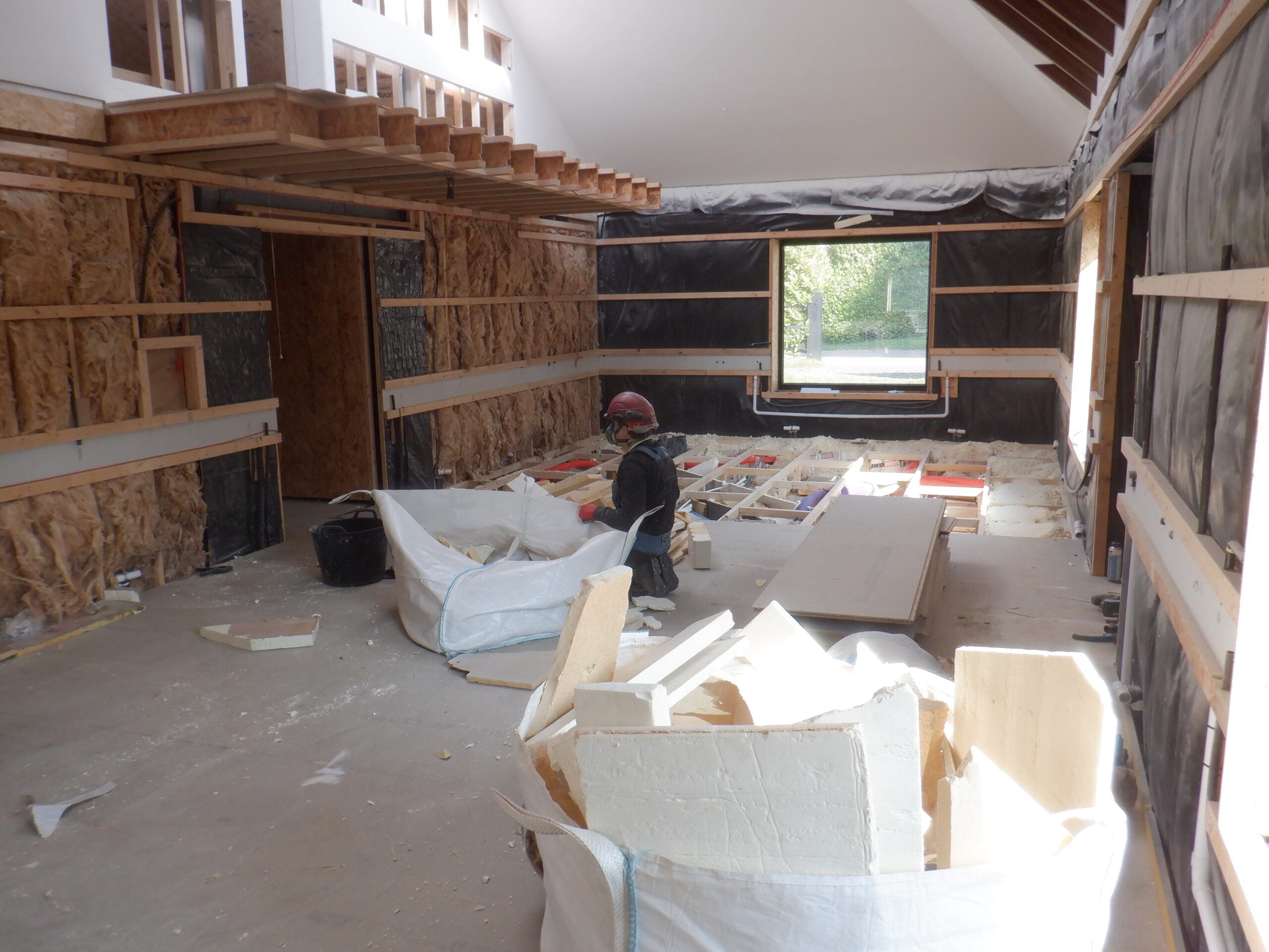
The first thing to do was to empty the entire room of all the items we had stored in various corners and move everything into our Kitchen, so we could lift the floorboards up.
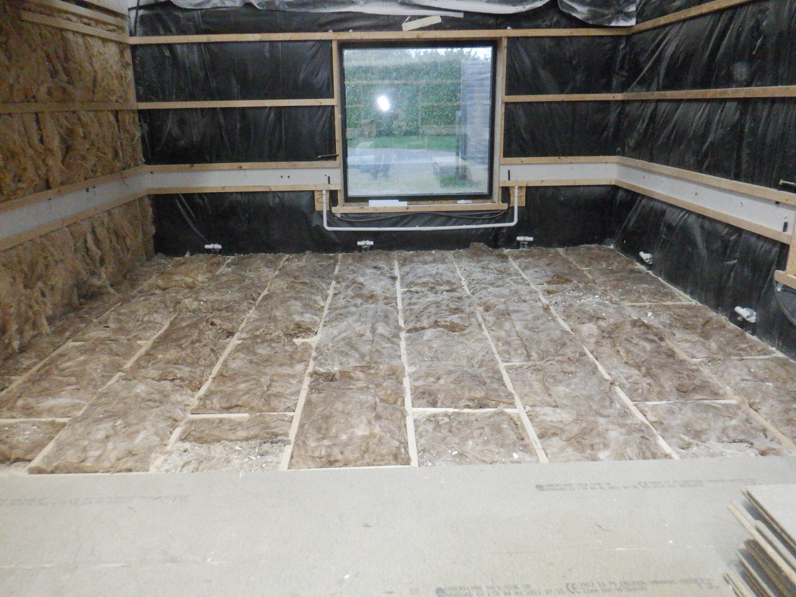
We started at the right hand end of the room, standing at the hallway door but it was locked into place by the tongue and groove system. Therefore, we had to move all the floorboard pieces towards the left end, by about twelve inches and keep each row of boards unconnected so we could move each row more easily. Another thing we did during this process, was to label all the individual piece with a row “letter” and “number” for each piece as the whole floor have been measured and laid down to fit the two doorways etc. We didn’t want to mix any up and run into trouble later on. So we pulled up three complete rows at the beginning, under the “O” window, looking out to our swimming lane at the back, and started filling in the huge pile of insulation boards pieces we had prepared from our time of doing the roof rafters last year. They are stored upstairs so we started chucking them off our Gallery, bit by bit!
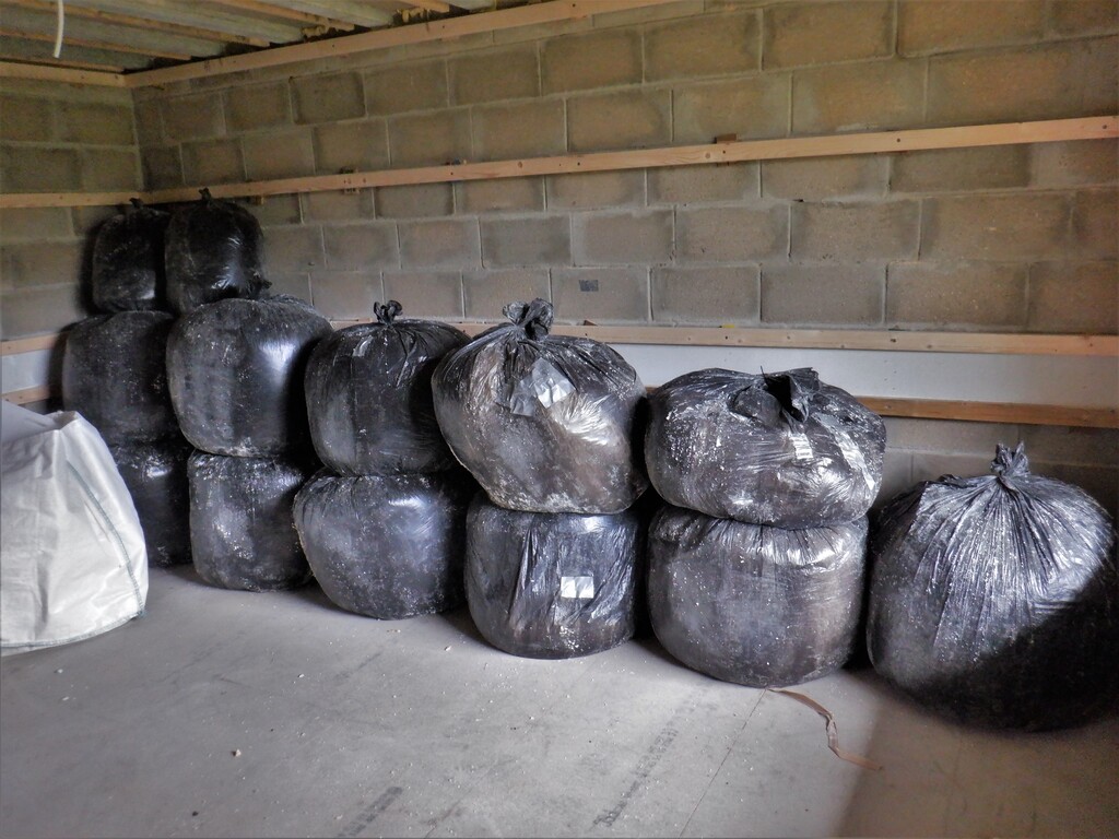
We also had six “ton” bags of random odd sizes and pieces of PU foam rubbish as well and we dragged each one down the stairs and along the hallways to the Great Room.
And not forgetting a room full of “fluffy” stuff we had previously generated, being stored in our Entertainment Room downstairs!
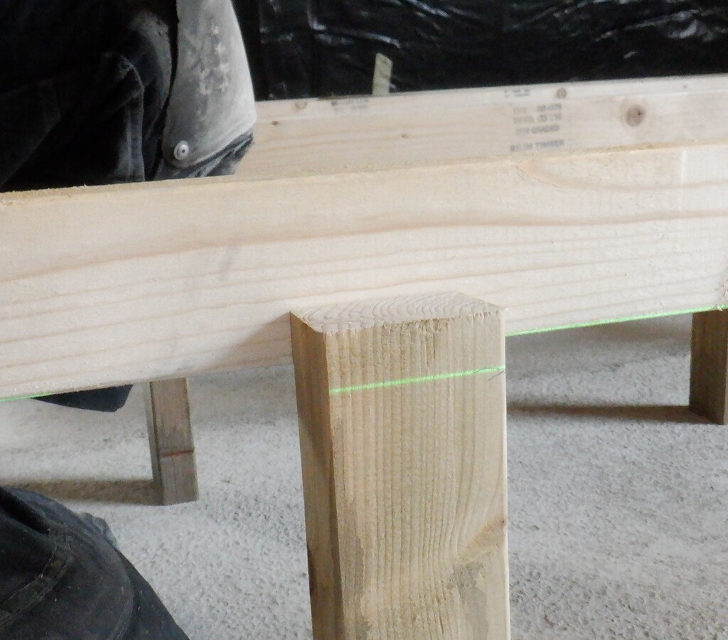
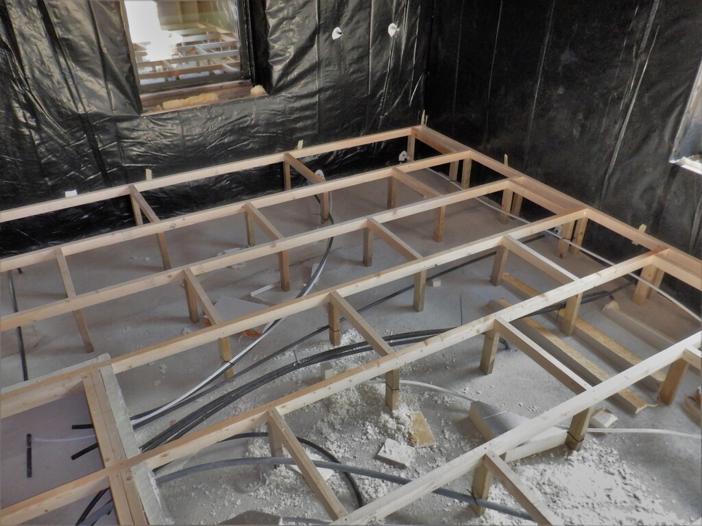
It is a slow job of laying down sheets of the insulation boards, skipping around air ducting, conduits, water pipes and so on. Building up the layers until we reach underneath the cross rails that is 63mm from the top. That is about 320mm to 330mm of cavity to fill up, depending on how thick the original concrete slab was. We first tried to fill the remaining space with fluffy fragments but we discovered that it is so light and “fluffy” (Of Course!!), that it would not keep still. We wanted to glue the floorboards down tight on the wooden framework and this fluffy stuff kept going everywhere!!
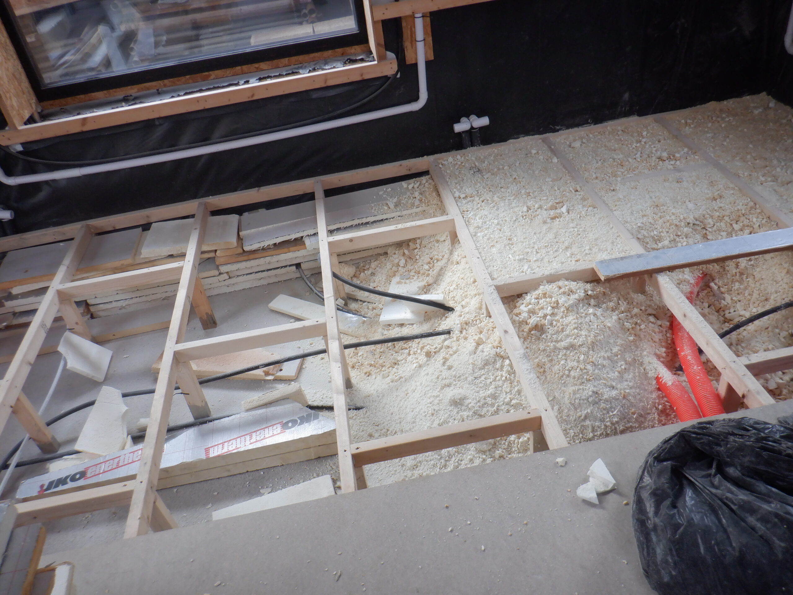
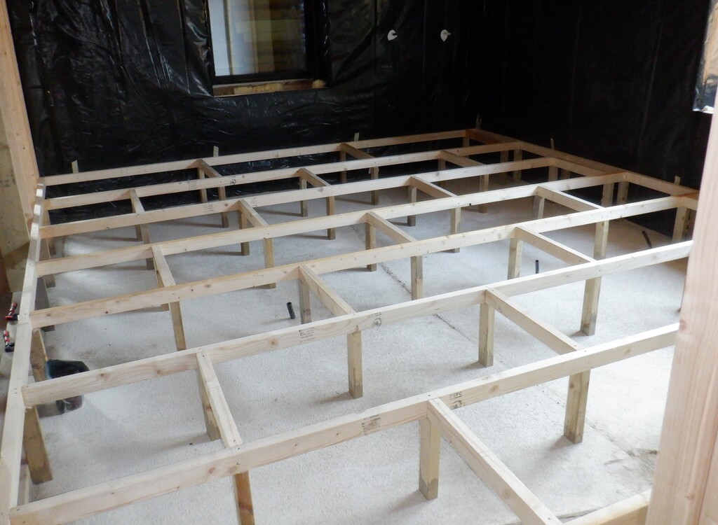
Starting to fill Greatroom floor
We used our spray gun foam to squirt a line of PU Glue Grade foam and then lay a floorboard on top. Next, we put in a collection of 50mm screws in each cross rail, to make sure that the 22mm thick chipboard boards will squash tight down onto the glue etc. For our first row, it started off at the left hand end, with a small piece, to bridge over the smaller spacing off the framework enough and the next board goes into the tongue and groove joint, getting knocked sideways to make sure the joint is nice and tight. This joint is also glued with more of our PU foam and this board is screwed down too. The final piece, is another larger piece, to finish the row. Each row always has three pieces but the first and last piece changes in size by approximately 600mm, to make sure that all rows do not have any joints aligning up consecutively, to improve the structure and strength of our floorboard generally.
We then carry on doing each row in turn, making sure that we knock each row tight into the previous row, by using a small piece of the same chipboard material that has a groove on it, plus a piece of CLS timber glued on to the back edge so we can thump it hard using a club hammer, to provide a reinforced tool, that slots into the tongue on the board and that will not damage it, while we are knocking each piece into place.
First row down
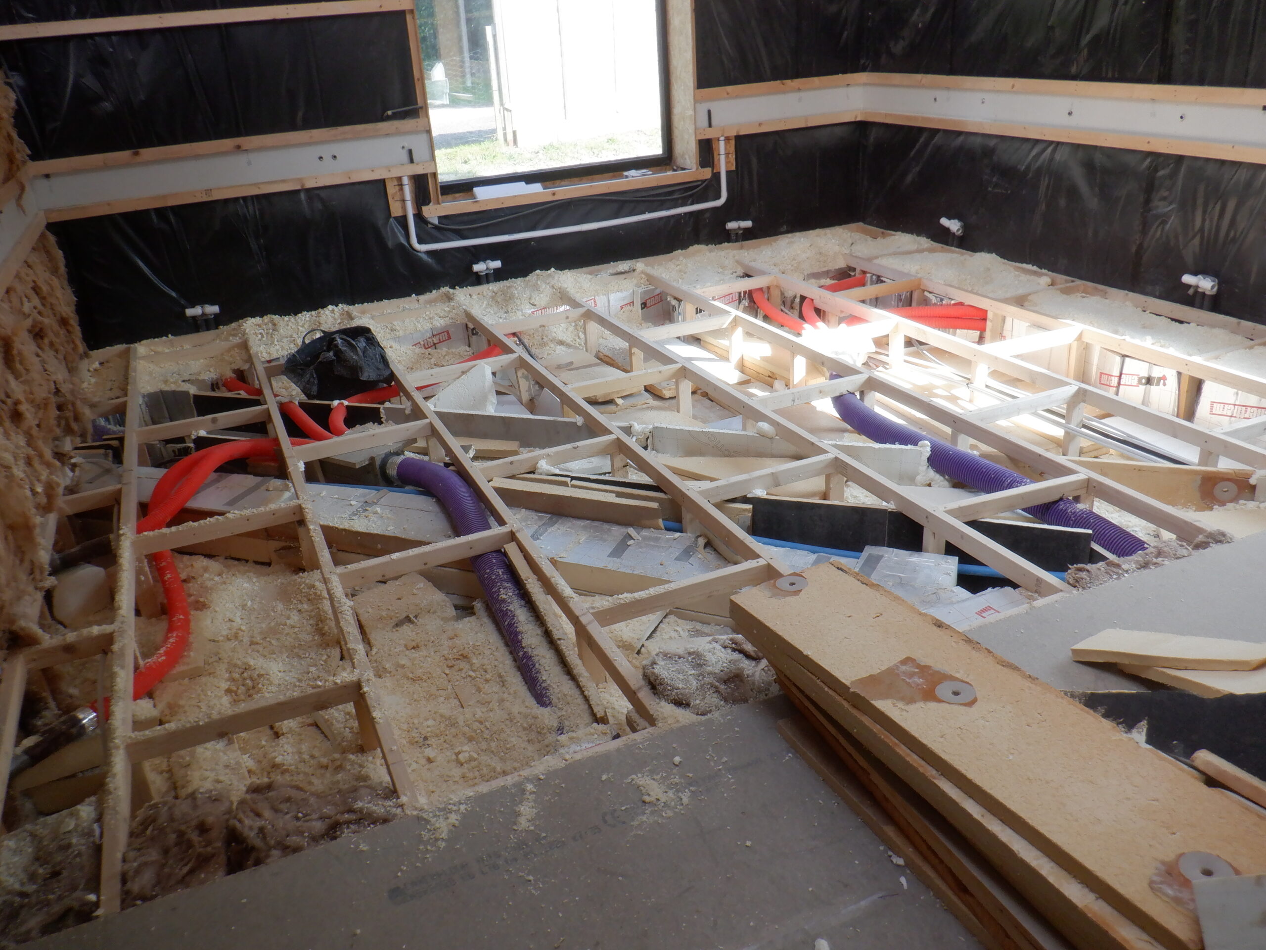
One of the jobs we had to do while the floorboards were up, was to seal the ventilation ducting to our wall distributor modules. The orange flexible 50mm conduit comes from a four way splitter and each duct goes off to various locations around the wall. Each end needed sealing up with aluminium sticky tape.
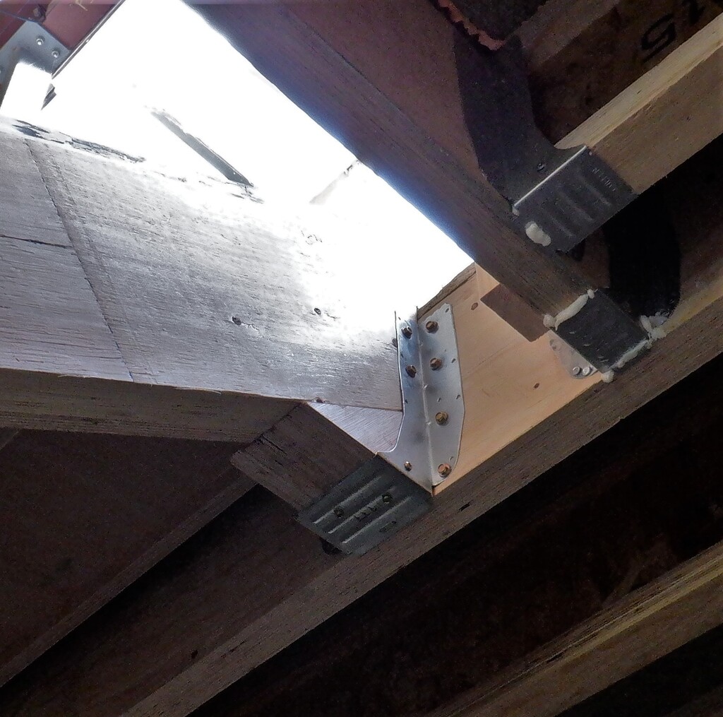
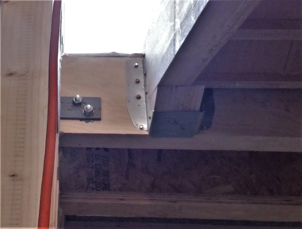
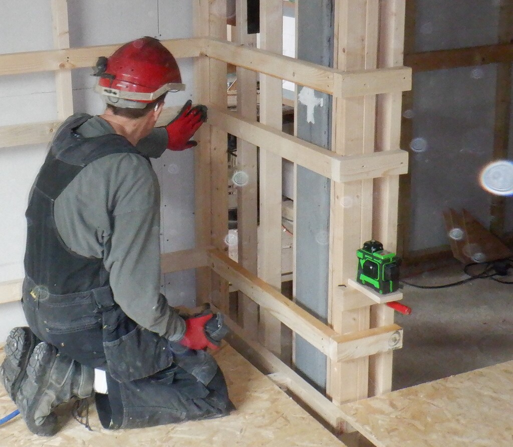
We got to the spiral staircase position, row number “G” and “H” and one of the thing to do was to reinforce the flooring, to make sure that this zone is strong enough to support the entire stair case, in one single small spot. We are going to have a pillar going up the middle of the spiral stairs and it measures 200mm across, which will be the main load bearing element. So, we built up the framework structure, putting in a zone of 400mm by 600mm of solid layer of CLS timber pieces, all glued together into a single block. This is then supported underneath by a couple of sturdy cross pieces using a wider 89mm CLS pieces and then finally, underneath those two pieces, we put in four legs down to the concrete floor slab, two legs under each cross piece. Everything glued and clamped together.
The final top surface was planed smooth, to remove excess glue and excess timber and made it level across neighbouring floor joists.
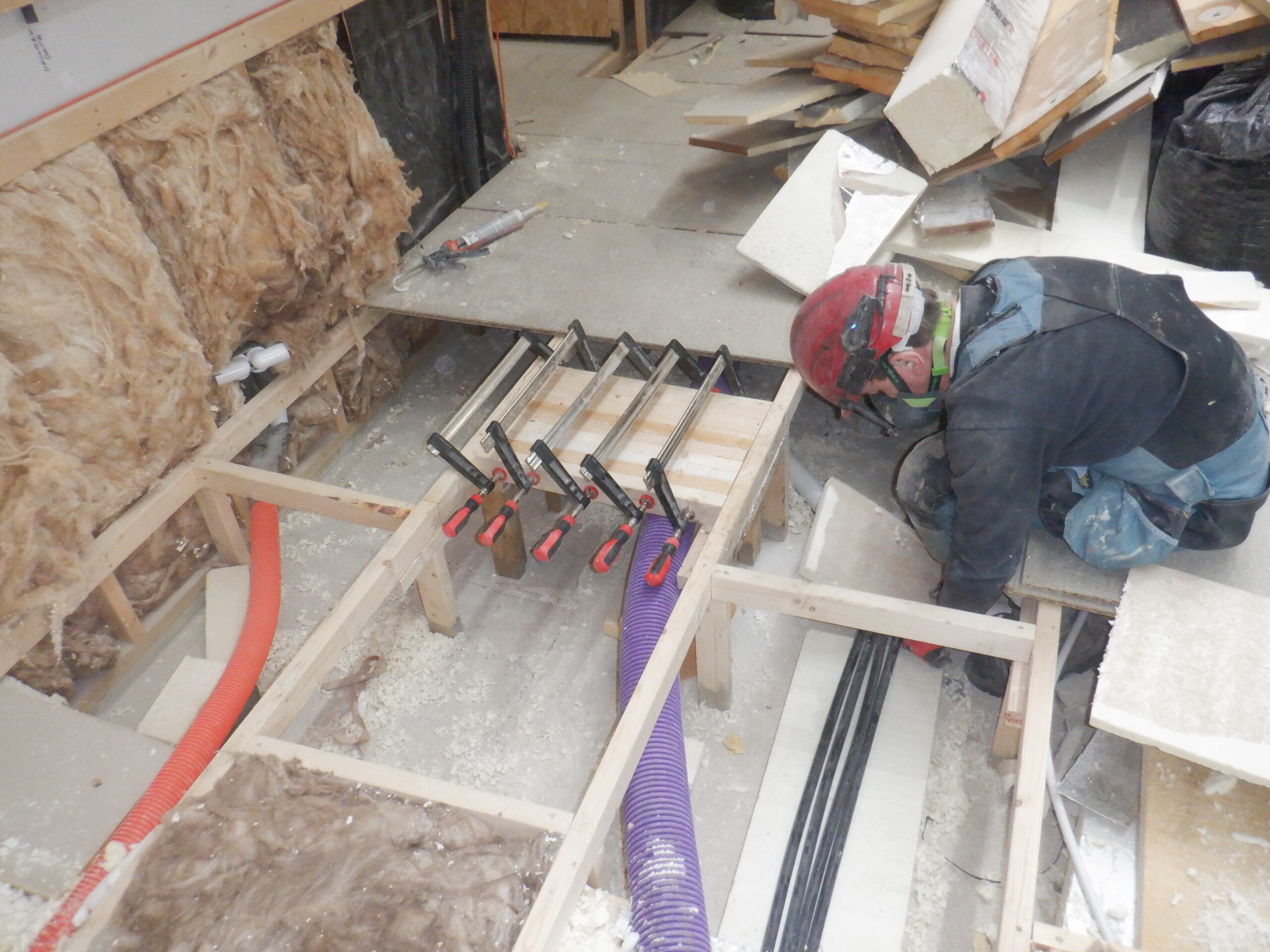
Reinforcing floor for spiral staircase
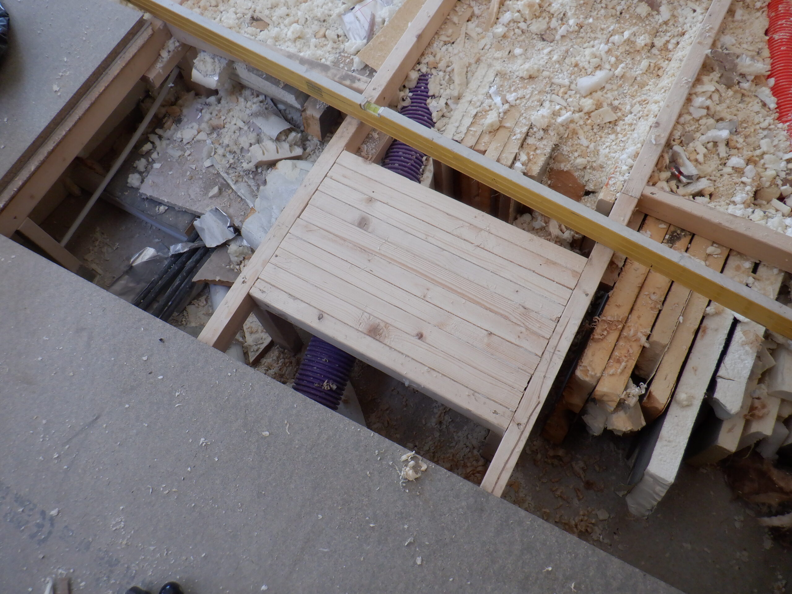
Staircase Reinforcement smoothed
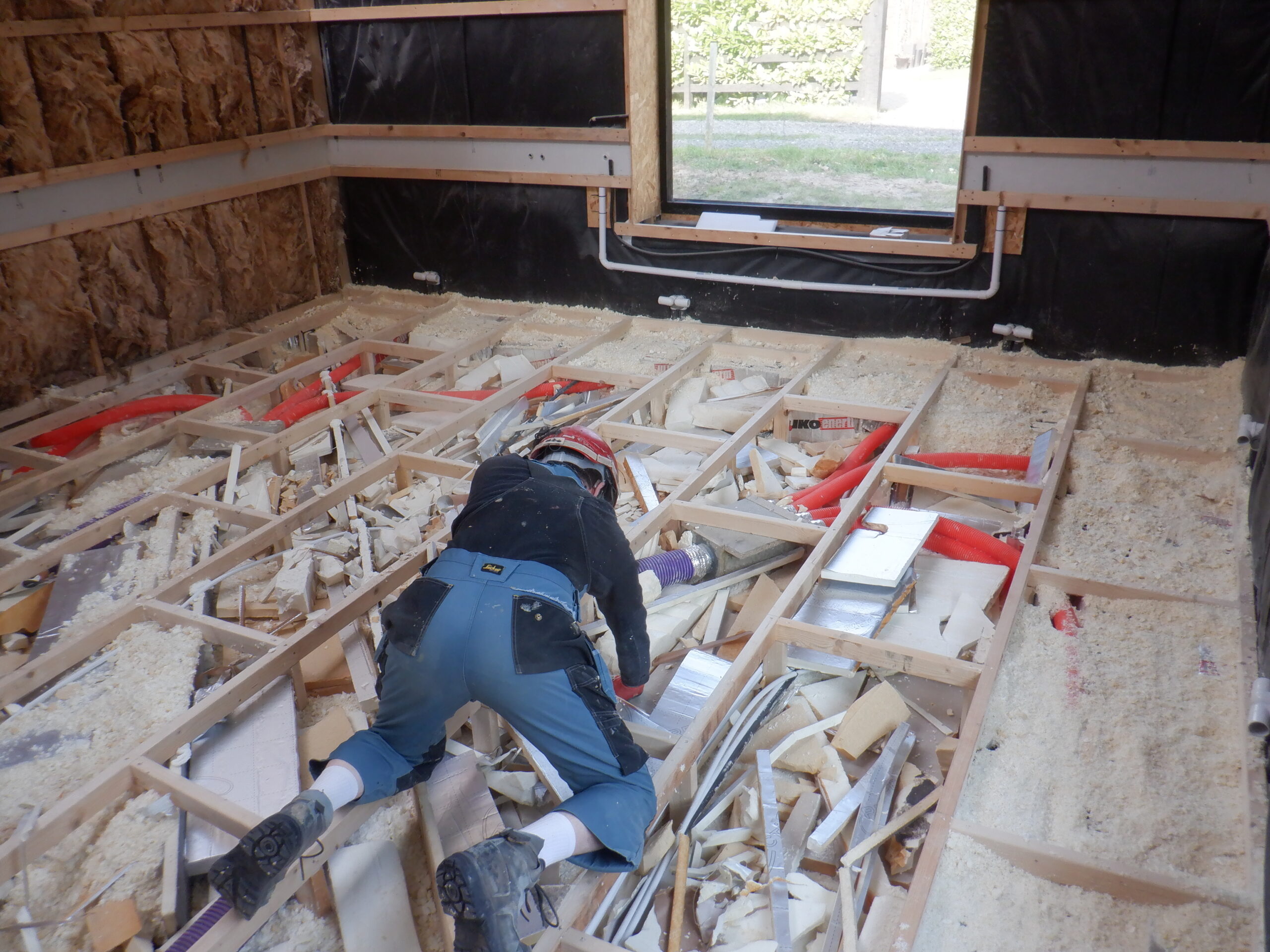
We built this reinforced spot near a couple of existing legs so we have six legs in total in the immediate zone but there are a further two legs only 300mm away and also the floorboard itself will help spread the load right across all the framework and in turn, down to the concrete slab.One of the things we tried to do, is to run our shredding machine and get the output to go straight down into the cavity space under the floorboards but it proved rather awkward to generate a constant flow of shredded bits coming out of the machine. The machine itself couldn’t shred the foam and let the pieces fall naturally downwards underneath the machine, it was “fluffing” up all over the place! So, we tried to combined the large vacuum machine we had used before, but instead of filling up domestic bin liners of foam bits, we tried to connect a plastic conduit to the bottom of the plastic bin liner so that the shredded bits would fly down the tube and into the floor cavity. But, as soon as the bits started building up in the bottom of the black liner, it would block the output tube and no more fluffy bits would fly along the tube!! We abandoned that method and just took each lump of foam and fitted them in a collection of random positioning, mixed with fluffy shredded bits we already had done months ago. We also took many of these lumps and arranged them into larger blocks before putting more fluffy stuff in on top.
It was a bit fiddly but we got there!
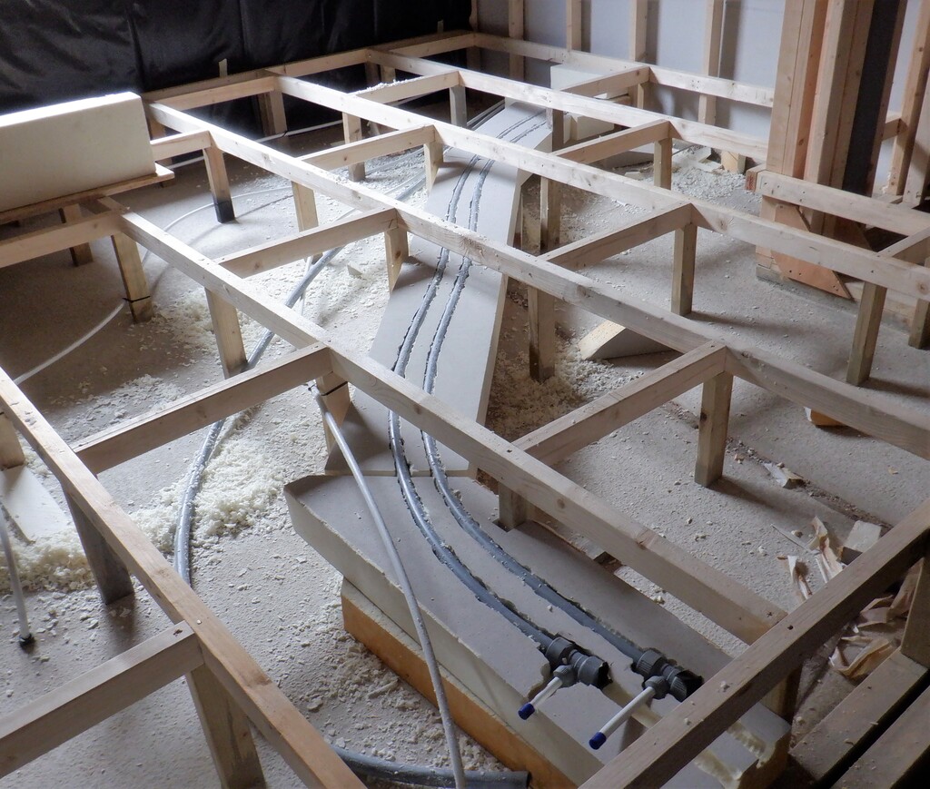
We got the middle section where our Utility services runs across the room, heading at a diagonal for half the distance and then straight to the Conservatory doorway point. We will have air, electricity, compressed air, and hot and cold water coming in and out of this zone, so we needed to seal off the rest of the floor on either side, to stop an avalanche of fluffy bits falling into this section. So, we cut pieces of 25mm thick foam sheets and glued them vertically into place. The 100mm “purple” air pipes, four of them in total, were supported with lumps of foams and then held into place through these vertical barriers. All the other utility like water pipes was already fixed in a neat line coming through a sheet 12mm board of plywood.
Now, we tackled the last furlong of the race of filling the floor and gluing and screwing down the floorboards, to the left of the Utility service channel, by removing all the floorboards and heaping them up over on the finished side, stacked in the correct order.
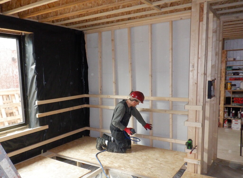
We went around the edge of the room, nearer to the outside world, and put in a solid arrangement of narrow strips of foam boards so that we maximise the heat retention for the house against any temperature differences in the outside world.
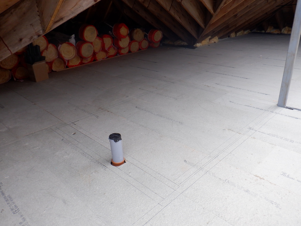
This left the middle area of the space to be filled up so we spread out all our remaining chunks of foam rubbish, and poured in all the last of our fluffy bits. And finally, topped the whole lot with two or three layers of 100mm glass wool, depending on how much there was to finish off.
Starting on second half 1
Starting on second half 2
Second half nearly filled
Second half ready for floor boards
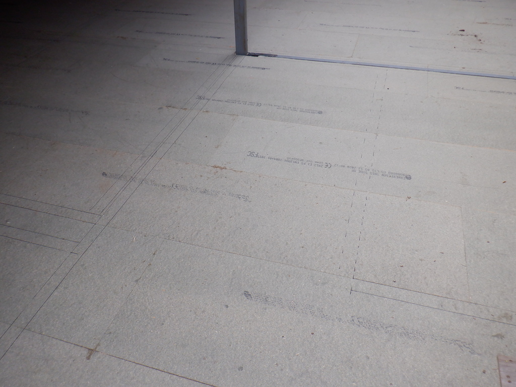
We then could get on with laying down the final rows of the floorboards, getting them glued and screwed down, all the way to under the window looking out to the Loke. The rows that went over the Utility Services, we had to mark very carefully to exactly where the floor support framework is located because we needed to know precisely the positions of the “hatches” that we will cut out after the floorboards have been glued together using our construction PU glue instead of the PU spray glue. We also put a layer of parcel sticking tape on the surface of the framework so any excess glue that may leak through the joints, won’t permanently stick the floorboards down to our wooden framework!!
The final job was to get our track circular saw and slice down 22mm (and a bit), to cut our floorboards to those hatch markings. It was a nervous moment because we couldn’t undo any of these cuts!! But, It Turned Out OK!!
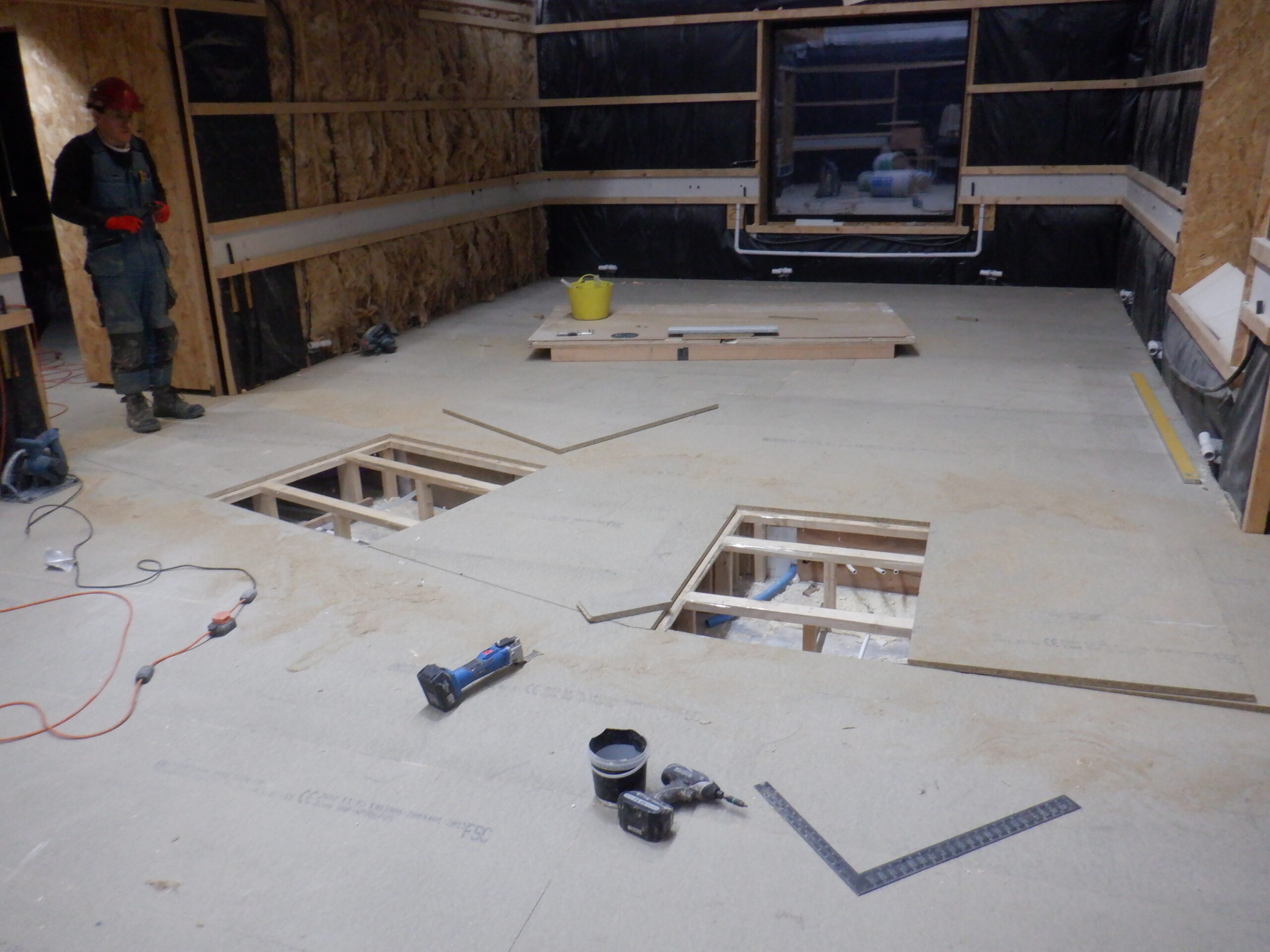
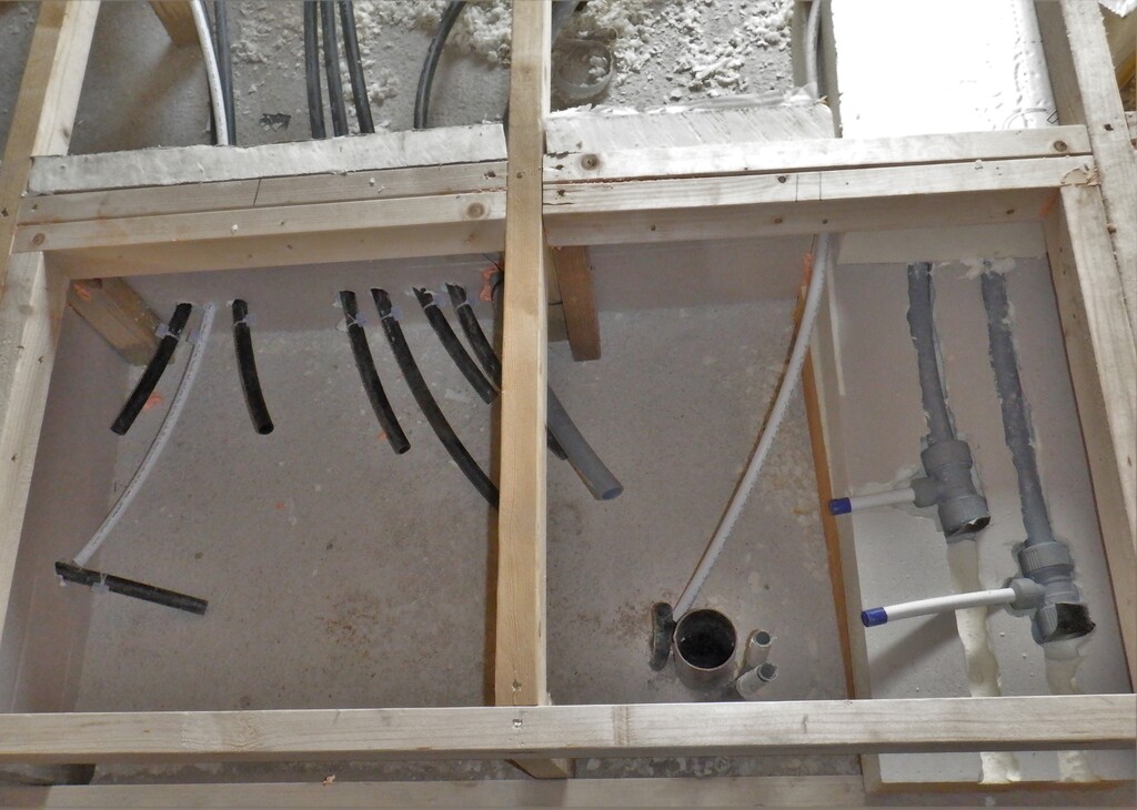
Central Service area Hatches made
That concludes permanently building the Great Room flooring, at long last! We can get on in building the walls next!