Category: Design

  • Driveway GeoGrid Plastic Modules Arrives for resurfacing the Loke

    Today, the first pallet of these plastic grid modules that helps retains the gravel and other crushed stony material has arrived. We ordered one pallet which has 260 individual modules.

    Driveway GeoGrid Plastic Modules Arrives for resurfacing the Loke

    Pallet-of-260-grids


    Each module measures 500mm by 500mm and its 40mm high.
    Driveway GeoGrid Plastic Modules Arrives for resurfacing the Loke

    A-pair-of-grids


    They have lugs on two sides and key slots on the other two sides so each one can be interlocked together to form a rigid strong grid that is then filled with all sorts of different material. We are planning to use recycled crushed asphalt tarmac recycled road material to create a darker finish. We have a design of two metre wide tracks, separated by half a metre.
    Driveway GeoGrid Plastic Modules Arrives for resurfacing the Loke

    Grid-connecting-lugs

    Driveway GeoGrid Plastic Modules Arrives for resurfacing the Loke

    LokeGrids


    Then at each entrances, we expand out and interlock more of these plastic modules to form a larger sturdy surface so our vehicles can turn in without scrubbing up the material and forming ruts and potholes.
    we are working with our neighbour and sharing the tasks, we will do the initial removal using our mini-digger to scrape and remove the old grass and dirt plus the two old cinder and bricks tracks. Then the neighbour would take over to lay down the crushed asphalt material, compacting it in sections and shaping it so any rain water would collect towards the centre of the Loke and run down hill to the soakaway module that we will have made later on.

  • Glazing Framework Type, Shape and Size Final Adjustments

    As a companion to the report Winter Cold Virus Hits the Workforce!, this blog describes the last two weeks of our building work.
    so with the background noises of coughing, sniffing, sneezing and talking with croaky voices, we have been analysing the design of our Glazing Framework for the Skylight. We are thinking of reducing the number of glazing wooden rafters from the regular 600mm spacing to more like 1000mm instead. This would make the aspect of the skylight more pleasant to look at and to look through too. It would mean less physical number of elements to construct, assemble and install.

    Structural Analysis

    But first, we had to analyse the structural requirements of our roof to make sure the glass can take the strain and loading of various weather conditions, like for example, a foot of snow or gale force winds, as specified in the Building Regulations for our easterly region. The result of that research was that our primary glazing layer needs to be 6mm toughened glass, spanning the 1200mm by 1000mm of support.

    Size and Spacing

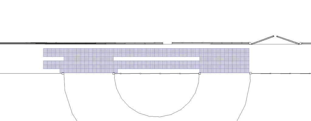
    Next, we took each section of the Skylight in turn, to adjust the size of the glass so it is a regular spacing, for each room upstairs, taking into account the maximum we are allowed as per calculation of research we did, as follows:

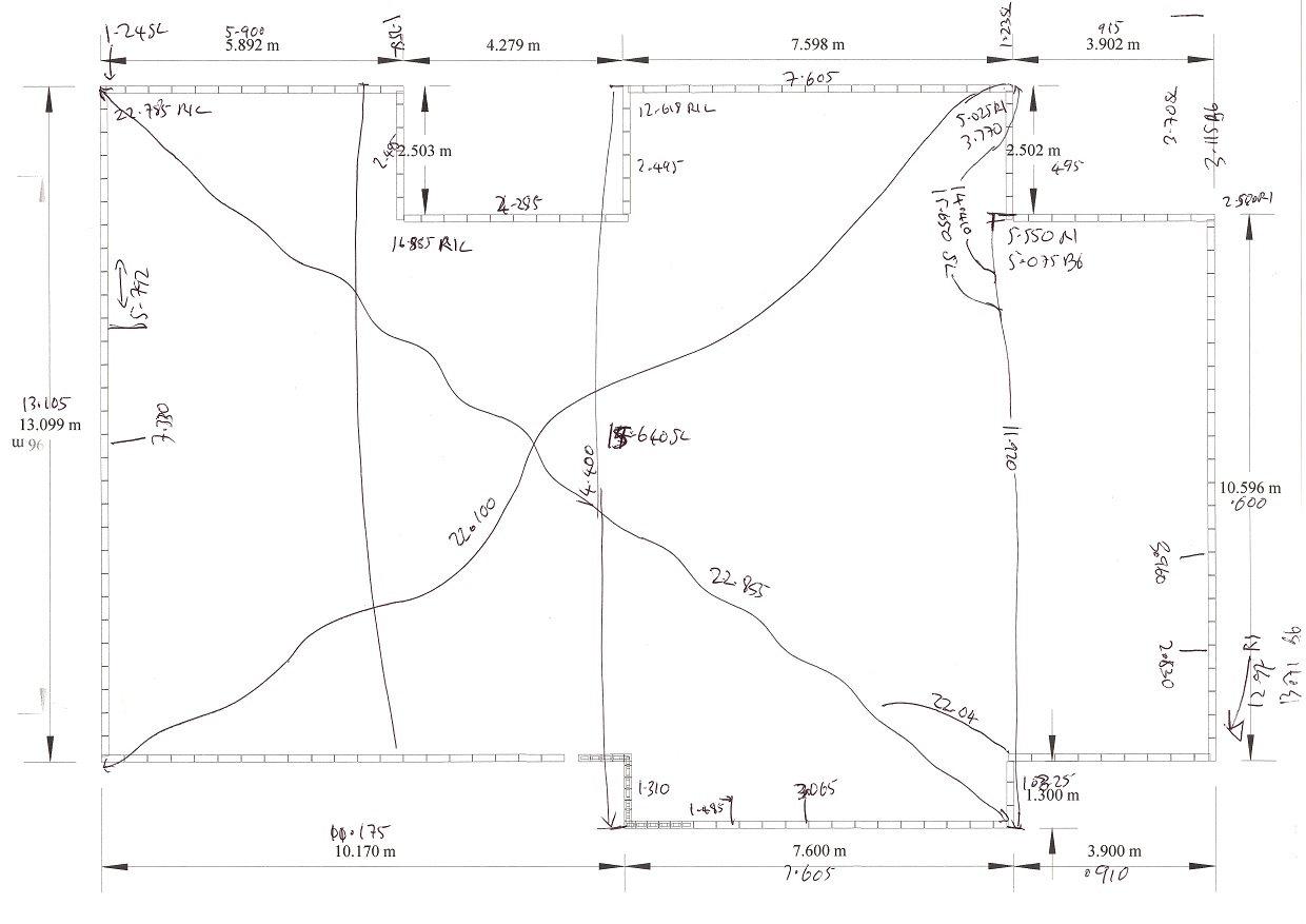
    • Great Room: 1 module – 1200mm and lots of triangular pieces
    • Spare bedroom: 4 modules – 1011mm
    • Hall & Stair: 2 modules – 813mm
    • Study: 2 modules – 1008mm
    • Workshop: 5 modules – 1061mm plus more triangular pieces

    The other side of the skylight (where our solar electric collectors are located), starts with more triangles and a 1200mm section over the great room then a regular spacing of 917mm most of the way along the whole length, in 13 modules followed by a last few triangle pieces. This deliberate design choice allows us to fix and clamp the sloping wooden rafters right through the ridge beam for extra strength and security and allow

    Thermal Properties

    the solar panel modules to all the same size.
    Another part of our analysis we have been doing, is the thermal properties of these glazing units, whether the cost of double or triple, or even quad glazing would payback and how quickly. Plus, the added complications of wear and tear to these sealed glazing units, during a hot and cold heat cycle and that causes physical stresses to the joints that seals the layers of the glass panes together. Thermal expansion is one of the most powerful forces out there and there is nothing anyone can do to stop it, apart from engineering the joints and seals to cope with the stress and strain of this physical effect.

    Summary

    At this moment, the results of our research in heat loss, the weather conditions and thermal properties of the various glazing options, here is a summary (for the whole Skylight):

    • Heat Loss: 12050 kWh per year using a 10 year historical data
    • Energy Cost: £1205 per year with single glazing
    • Double Glazing extra: £2000 to buy but Energy cost cuts dramatically to £140; payback time is 2 years!
    • Triple Glazing: £3000 to buy; £85 per year for energy; 3 years payback time
    • Quad Glazing: £4000 to buy; £60 per year; 4 years payback time.
    NOTE: One aspect of this research that have not been included in these calculations, is the Solar Gain factor. This is a very powerful energy source and our Skylight is very large and will be collecting a great deal of solar energy during the daylight hours and we haven’t incorporated this into our calculations. But roughly, it will save us even more money and the payback time would reduce even further!

    These payback times are all based on a fresh start as the building is constructed, but it would be a completely different story if after 20 years, we have to replace the glazing units and it would be a pure fixed cost spread over the lifetime of the product. Everything fails eventually so one has to get into the frame of mind that we should be saving some money away in a piggy bank so we are ready for the replacement. Glazing units are now given a lifetime of 20 to 25 years so if it costs £4000 up front, then we need to put away £250 per year for 20 years, as no doubt the prices will rise too! eeek!
    Our next job is to translate all this into a construction plans, building an order for materials and plan procedures etc.

  • Perimeter Walls Measured and Drawings Updated

     We had a bit of spare time today after we had completed the job of installing the temperature probes conduits around the Energy Modules so we spent an hour measuring all the Perimeter Walls. We did all the lengths (14 straight sides) from corner to corner, then distances from known points already in our drawings like the Swimming Lane, and also did some diagonals across the whole building to confirm that our drawing is reflecting reality.

    Measuring-the-walls

    Measuring-the-walls

    We will update our architectural drawings so we can then know how much this is and how much that is, for example, the amount of timber we will need and how many sheets of wall panels etc.

    We had some feedback as we were doing this task, and all of the straight sides measured within 10 mm of what the construction plans said, apart from one corner at the front where it is a whopping great offset of 25 mm – Oh No! Grin!

  • Submitted House design to Building Control

    We went into Great Yarmouth this afternoon and handed over the package of our construction plans and structural calculations to our new Building Control inspector Kenny Brown.

    The package contained 27 pages of A3 drawings, 20 pages of a summary and overview of the project and 150+ pages of calculations!

    Now we can start work on the preparations like the site clearance etc.

  • Earth Tubes Design Conclusion!

    We have finally settled on a design of connecting up all the earth tubes and getting the air in and out of them! We have 12 tubes all together, each one being 150mm (6inches) diameter internal) in order to provide time for the air to exchange its thermal energies with the surrounding thermal mass! The 12 tubes is equivalent to a single 600mm (2feet) diameter pipe!

    After consulting with our friendly structual engineers, who advised us that our original design of using concrete blocks to construct a chimney and tunnel to pass the air down to the tubes, has potential problems at the joins due to the loading pressure from all directions but especially the sides, at 2.5m (8feet) depths! They advised the use of pre-casted concrete pipes segments to make the chimney and tunnel / chamber but this lead us to realise that we could route the tubes themselves upwards with 90degrees corners and terminate them inside the buildigs! This makes it so much easier and avoid mssing around with concrete blocks, pouring concrete around them and other reinforcing methods or drilling holes in the sides of concrete pipes!!

    So Many Thank goes to our engineers at Burrell Partnerships of Norwich!!

  • The first meeting with our Structural Engineer

    Paul Burrell of The Burrell Partnership in Norwich visted us today to discuss what we needed from a structural engineer. We had a fruitfull time and aggreed to retain Paul’s firm as our engineers. We agreed a fixed fee of £1000 for the job. We will now send them the plans for the garage so calcs. can be done.

  • Groundworks design

    3D image of the Groundworks I have been busy for a while sorting out all the below ground design for the house. This is now basically complete and just waiting for the structural engineer and Build control approval.