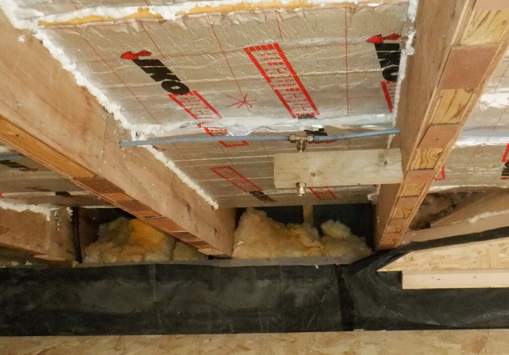
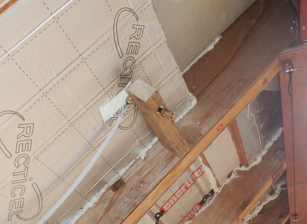
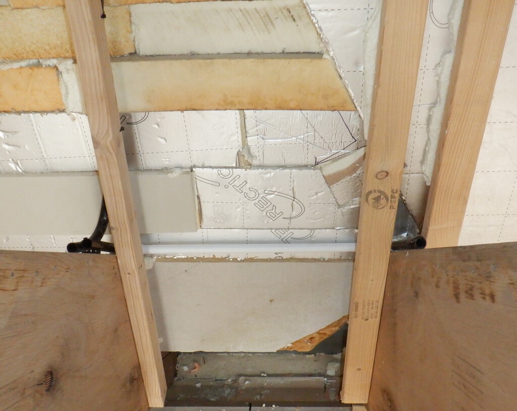
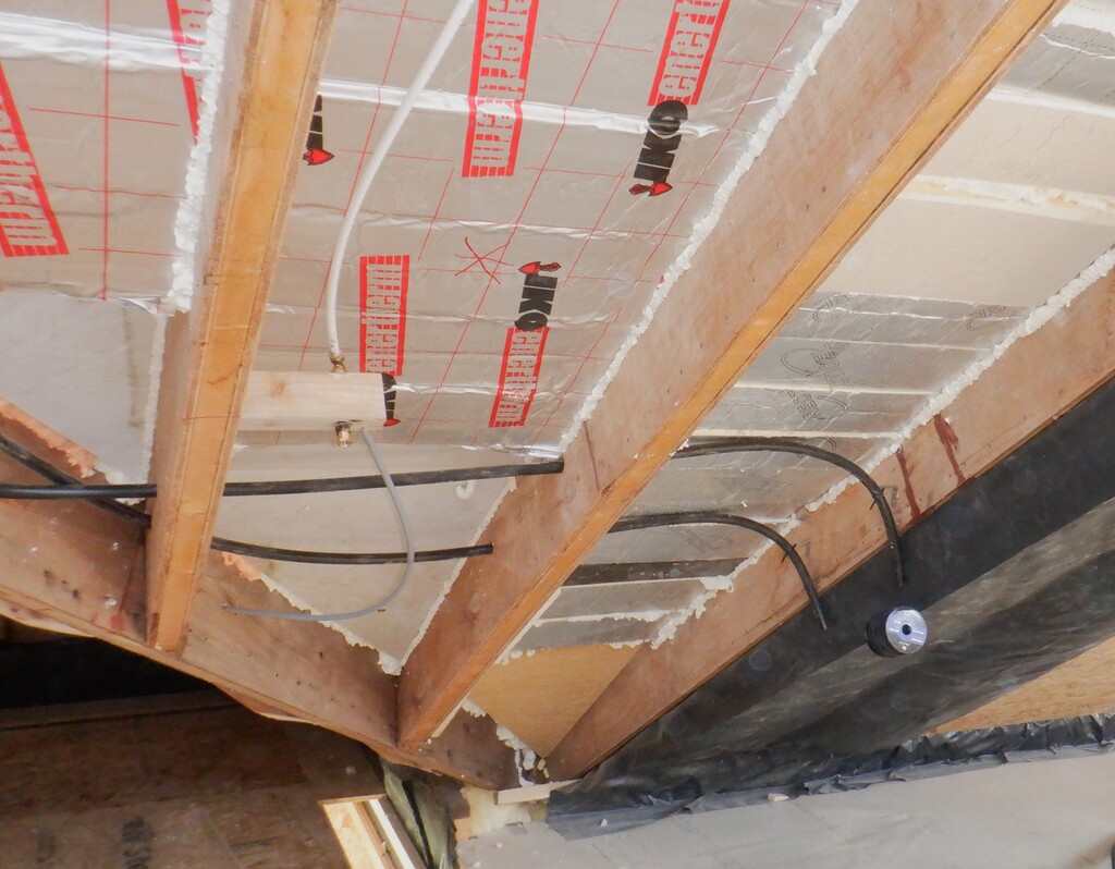
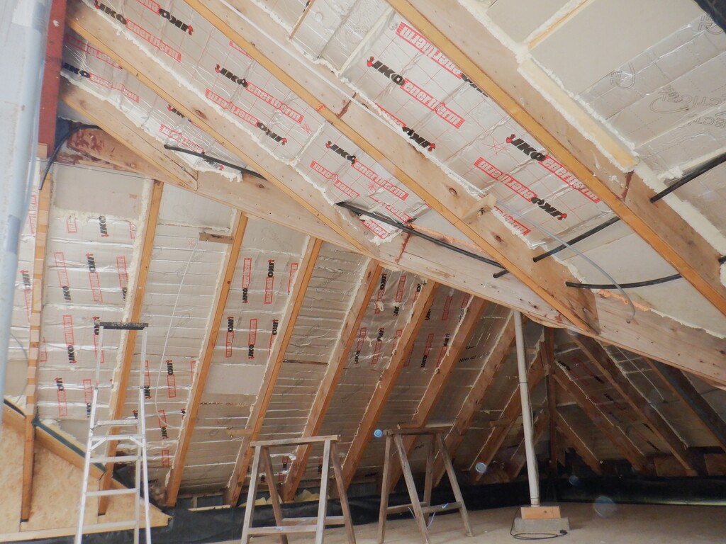
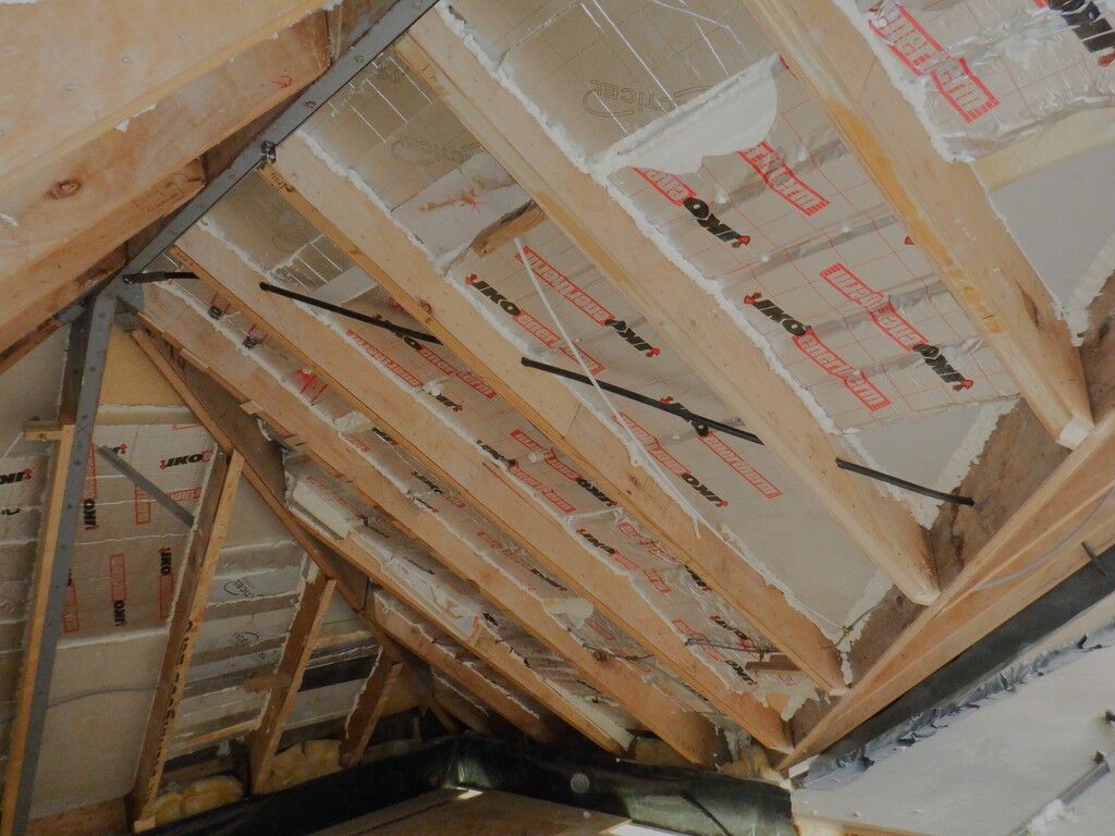
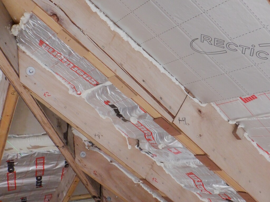
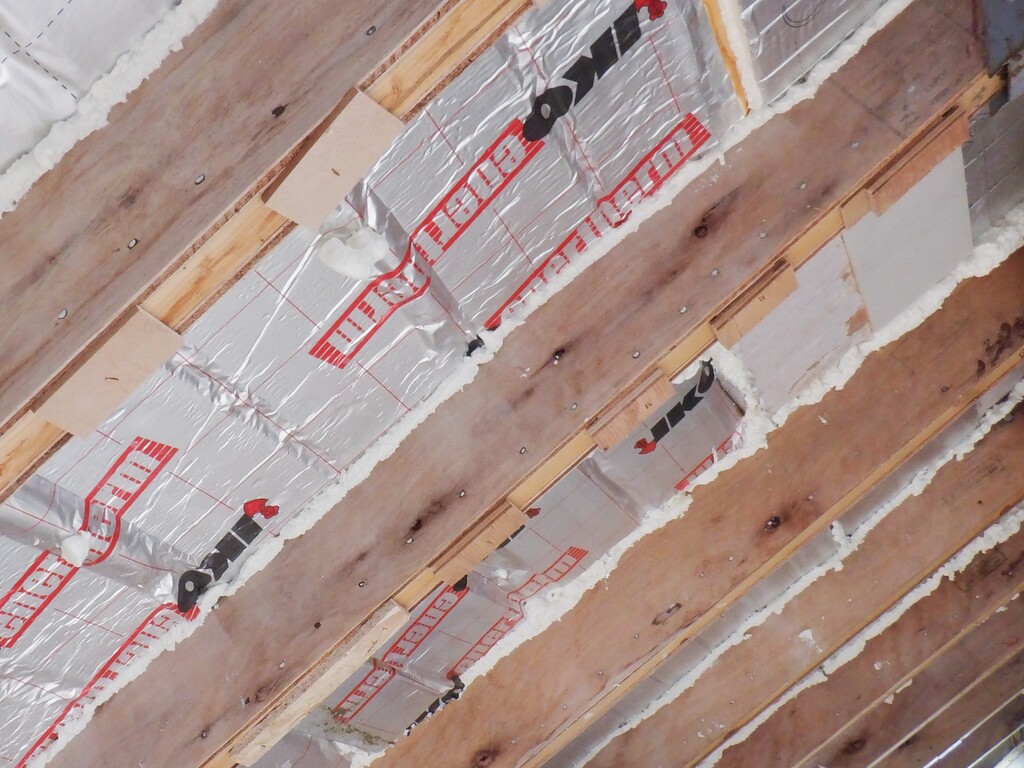
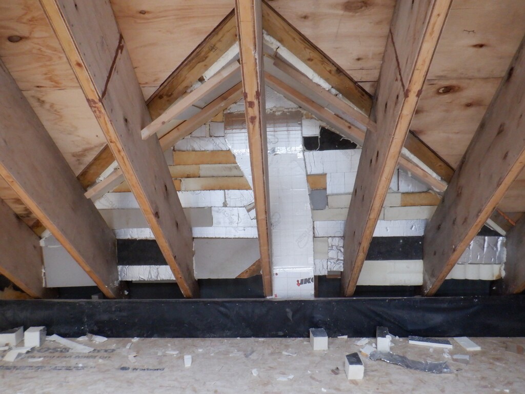
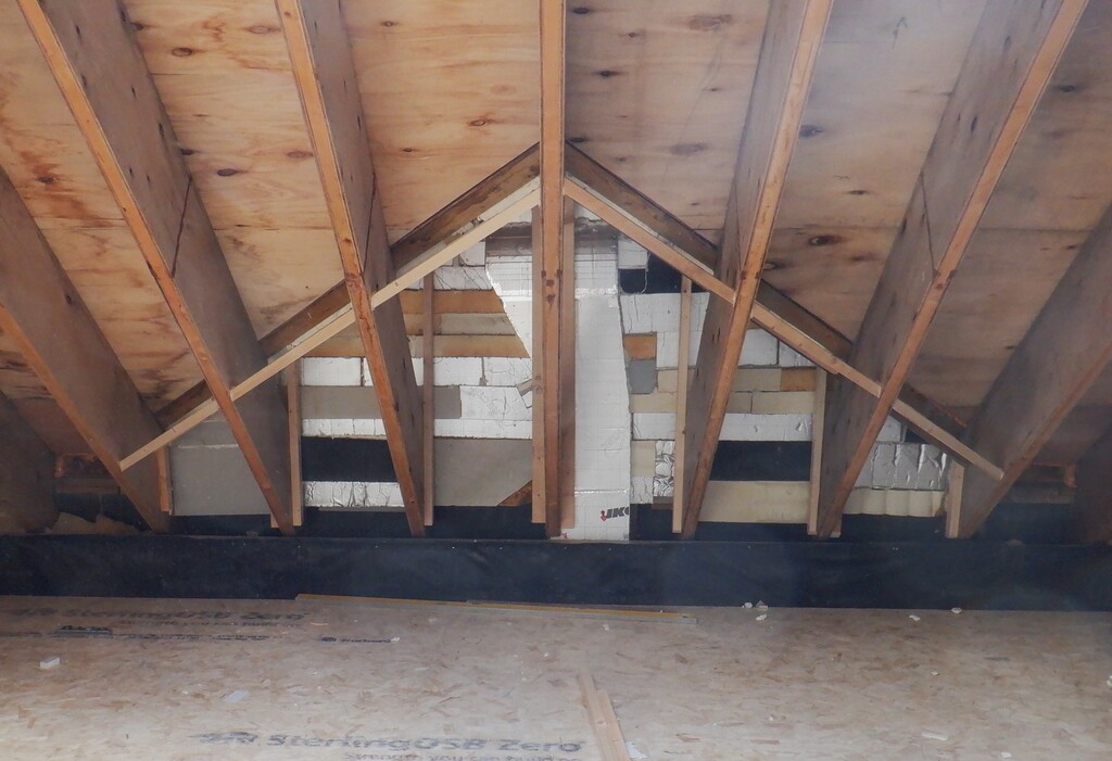
But, the first job is to prepare the framework and make sure that it is nice and solid, without any gaps etc.
So, using our new High Platform, we went along and blasted out all the crevices with compressed air, put in short lengths of 10mm PU “sausage”, squashed into the gaps, to help to reduce the amount of sealant, squirted in plenty of sealant and bringing it all up so everything is more or less smooth and level.
Next, we gave the windows a thorough clean on both the outside and inside. Shaun went outside on top of the roof with a bucket of hot soapy water and armed with a squeegee and sat on the Skylight itself. He lent over to reach all corner of each window with the microfibre scrubber pad and then drew off the water using the rubber scraper. The windows haven’t been cleaned for several years so it took a while to get the dirt washed off. Shaun shuffled clockwise around all twenty-two windows and ran out of energy, and clean soapy water, by the time when he reached the solar panels so we will come back another day to do those.
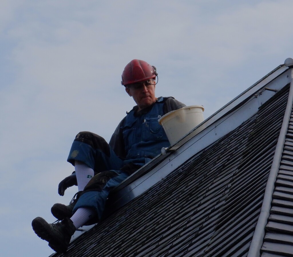
Shaun washing skylight windows
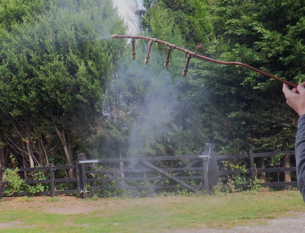
We will invest in a long handle cleaning tool that can telescopically extend out but also has a hose pipe going up the middle to supply a flow of water at the same time while scrubbing the surface. This tool will also serve to clean our seventeen solar panels as well. It will save us having to clamber up onto the roof tiles and be able to do this task from the ground itself, or at least, on a high platform at the gutter level.While this was happening, Stephen went around inside to clean the inside surfaces of the windows, using a little gadget that scrubs and sucks up the dirty water at the same time. But, it was also needing several washing cycles and each were polished with a microfibre cloth. He was standing on our high wooden platform. These windows needed to be extra clean because they won’t get a second chance after the double glazing units gets sealed in later in a few days.
We were considering what sort of battens to secure and fix up the glass units, and after thinking about making it out of Oak, we decided to phone our local timber merchant and ordered a set of planed 21mm square beading. They come in 4.2metres lengths and we calculated that we would need 23.5 pieces so we round this up to 25 lengths just in case. It is quite shocking to how high the price of timber is these days, it cost us about £1 per metre of 21mm by 21mm planed pine wood and only a couple of years ago, we paid £1 per metre for 63mm by 38mm planed timber!!
Next we adapted a compressed air sealant dispenser tool so that we can get a constant pressure and flow of the low-modulus neutral cure glazing sealant that we need to squirt all around the edge of the 28mm thick glass unit and make sure that it is completely filled in. The problem we got with our existing tool, is that it is too long. It was designed to take a higher capacity sealant tubes that were 1½ inches longer. It is a pity that there wasn’t a unscrewable section on the body of the chamber and therefore adjust the tool to take shorter sealant tubes.
We made an internal extender to take up the slack by cutting out three circles from a piece of 12mm thick cement board, measuring 47mm diameter, using a core cutter. These three pieces were glued and bolted together to squash the joints and waited overnight for the glue to set. Next we found a little length of 50mm wide plastic pipe which is a fraction too wide to fit inside so we sliced a very small chunk out of it so it can close up to fit smoothly into the gun. Then, we “turned” the solid cement plug very fractionally so it also just fitted smoothly inside the plastic sleeve. We made sure that the cement core was exposed by 5mm or so so that we can slide on a fat O-ring rubber seal over the cement core and sit snuggly down to the edge of the plastic sleeve. The whole lot (minus the rubber O-ring) was glued all together so that it forms an air tight plug with just a small hole down the middle to allow the compressed air to enter the tube of sealant. The O-ring squashes up tight to the ends of the sealant tubes and the cement plug also seals against the original rubber seal at the bottom of the gun.
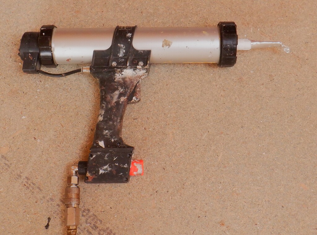
Air powered Sealant gun
It works very nicely without any air leaks! We can now go ahead to provide a steady flow of sealant for our glass units when we get them installed up into the Skylight.
We also modified some sealant nozzle to flatten them to allow the sealant to be pumped into narrow gaps around the units.
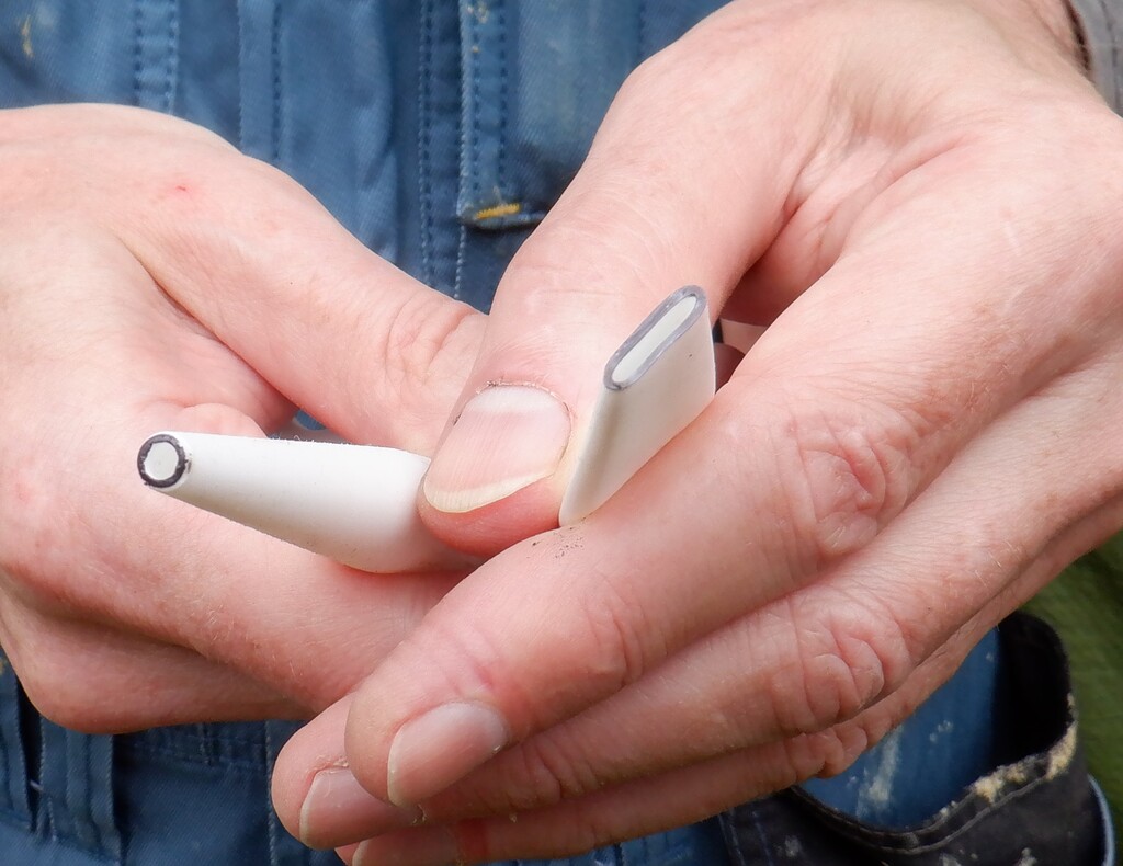
Modified sealant nozzle
Our wooden battens arrived this morning (Wednesday) and we got on with shaping all 25 pieces in our router machine attached to our router table. We just wanted to put on a single extra flat surface on the corner of the square 21mm by 21mm batten, to chamfer at a 45degree angle a third flat surface to provide a slightly more pretty finish than just plain square.
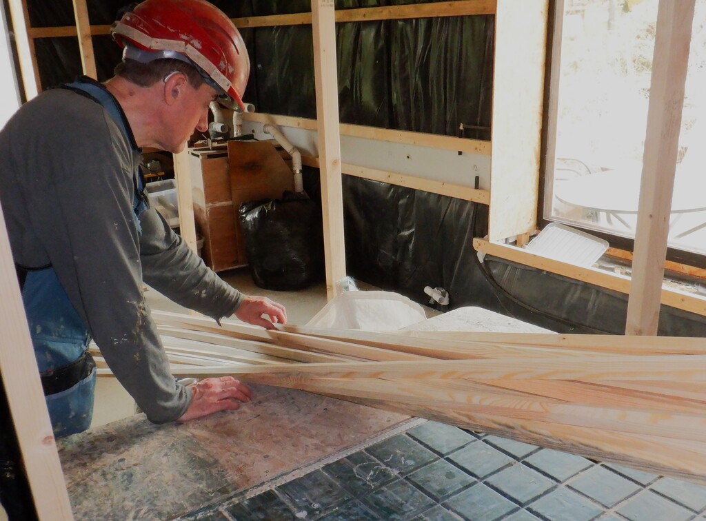
Double glazing battens
We then proceeded to give all pieces two coats of primer and undercoat, rubbing them between coats and get them ready for when we install the glass units.
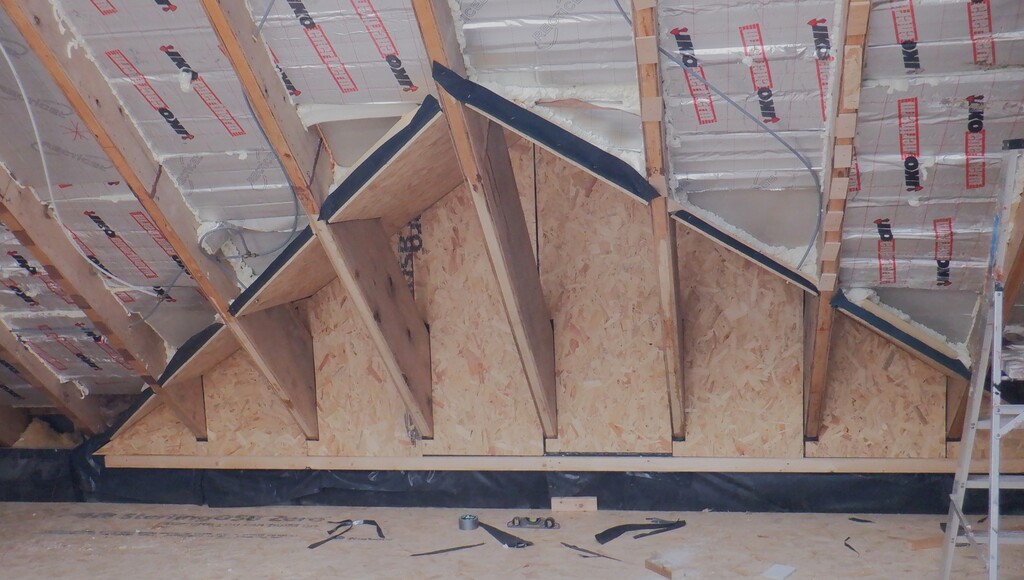
The last piece of work for this week is to make the moisture extraction system. It sounds fancy but all it is, is a tray of desiccant powder with a breathable tape over the top. We bought a heap of long 1inch wide by ½inch high extruded aluminium trays, measuring 5metres long. We then cut these up to make two trays, one at the top and another one at the bottom, in each square window and one tray at the bottom of the triangle windows. We had pre-built a little “shelf” in each window, to hold these trays of desiccant but, we discovered that some of them are slightly tight so we sliced off a couple of millimetres to reduce the height of these trays. We made 36 trays in all, with eleven of them reduced in height. We also rounded the ends and then taped a small piece of aluminium tape to seal off the open ends, to retain the crystals.
Lastly, we test fitted a couple of our triangle glazing units because we discovered that the last two units that we had to order again were not correct. We were cleaning off some sticky tape that the glass people had put on and cutting off excess amount of the tough sealant that is filled inside in between the panes of glass, when we tested the angle of the “right angle” corner and discovered that wasn’t correct. We then measured all three sides and the glass people neglected to take any notice of the hypotenuse and just assumed that these two triangles were exactly right angles when they were not. For some reason, they failed to noticed that these two triangles had special angles. We took them up to the Skylight and made sure that we couldn’t get them in. We will now have to go and chase them up and get them to admit their mistake. What a Fuss! We tested two more triangle windows, number 22 and number 19. Number 22 fitted in straight away but number 19 was ever so slightly too tight and we had to make some minor adjustments to the wooden framework so we could eventually get the glazing unit to fit into place.
Finally, just for completeness, we also tested one of the square windows, number 18, and it went straight in with no fuss at all.
We will carry on in dealing with the Skylight windows so it is all done, before we resume working on the Great Room.