Category: Roof

  • Slates Start Going Up!

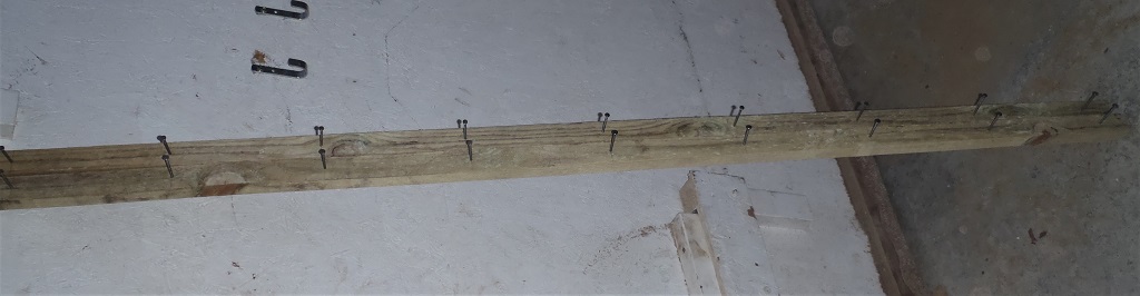
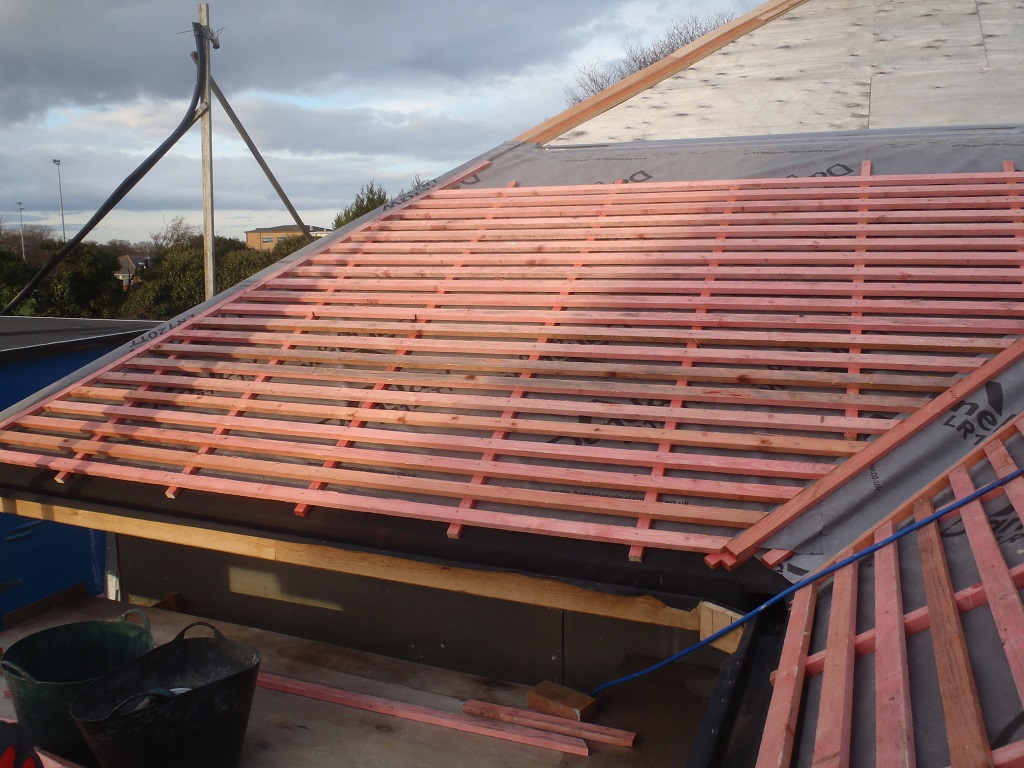
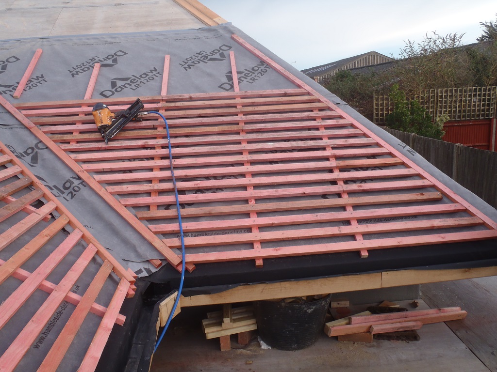
    For this week’s worth of work, with lots of weather interruptions along the way, we started the actual process of putting up our Slates! Using our new collection of tools and equipment, we projected a line up the roof at right angle from the Fascia to serve as the master reference line to work from. We started to use a blue chalk line to snap down lines from top to bottom but the rain nearly washed it away after doing the first 20 lines. So we reinforced the refernece line with a solid black marker pen and then marked each batten with 204mm spacings using a old metal tape which we prepared with marks so we don’t have to keep measuring the spacings each time.
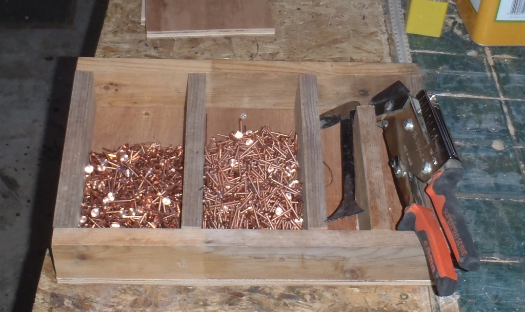
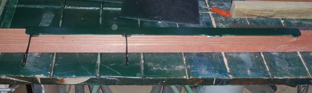
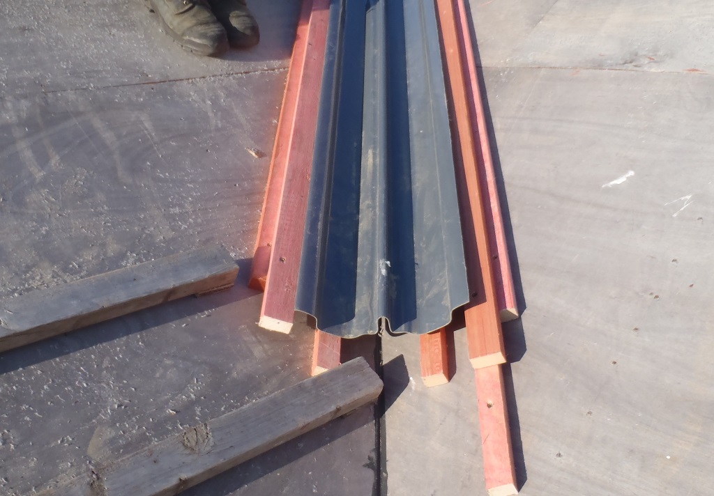
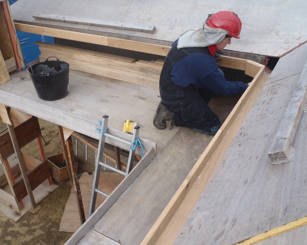
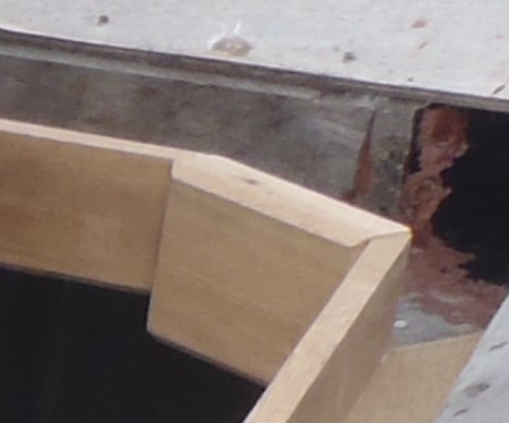
    After the marks were redone, the first job to do was to cover up the Gutters with our galvanised metal mesh (1 quarter inch spaced grid and holes) by aligning the bottom edge to the front of the gutter’s upright plank, stapling it down (on top of the rubber membrane already there) and then lifting the mesh up to the first line of the tile battens. Here we also stapled it down (using stainless steel staples) and then folded up the excess mesh backwards so we had a padding of this mesh to support the bottom line of slates hanging over the gutters (the padding acts like the missing third layer of slate). Finally, we screwed down a fixing cap of oak timber we had previously made, on top of the mesh and rubber, using stainless steel wood screws with nice large dome heads to clamp down everything. We trimmed off the excess rubber away and the whole thing now look neat and tidy.

    Slates Start Going Up!

    Gutter-mesh-and-capping-strips-installed-on-I


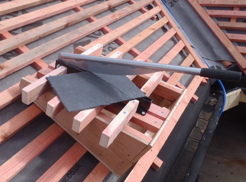
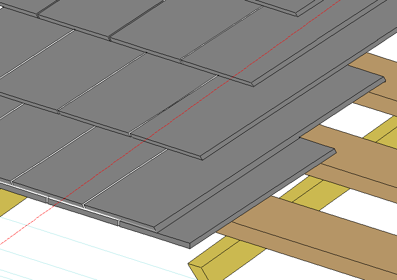
    After that, We started in the bottom outside corner (the join between H and I sections of the roof) and working left to right, started putting on the slates. But the first task was to slice a dozen slate tiles to remove 112mm off their lengths, because the first layer which is hanging over the gutters needed this amount removed to align up with the bottom edge of the second layer. This ensures that any rain water flowing down the roof is still captured by at least one layer of slate before reaching the guttering. We had to smile because we nearly got caught by the “rookie mistake” of not turning over these shortened tiles upside down so the bevelled edges are visible from below and the first and second slates sit flat together back to back!
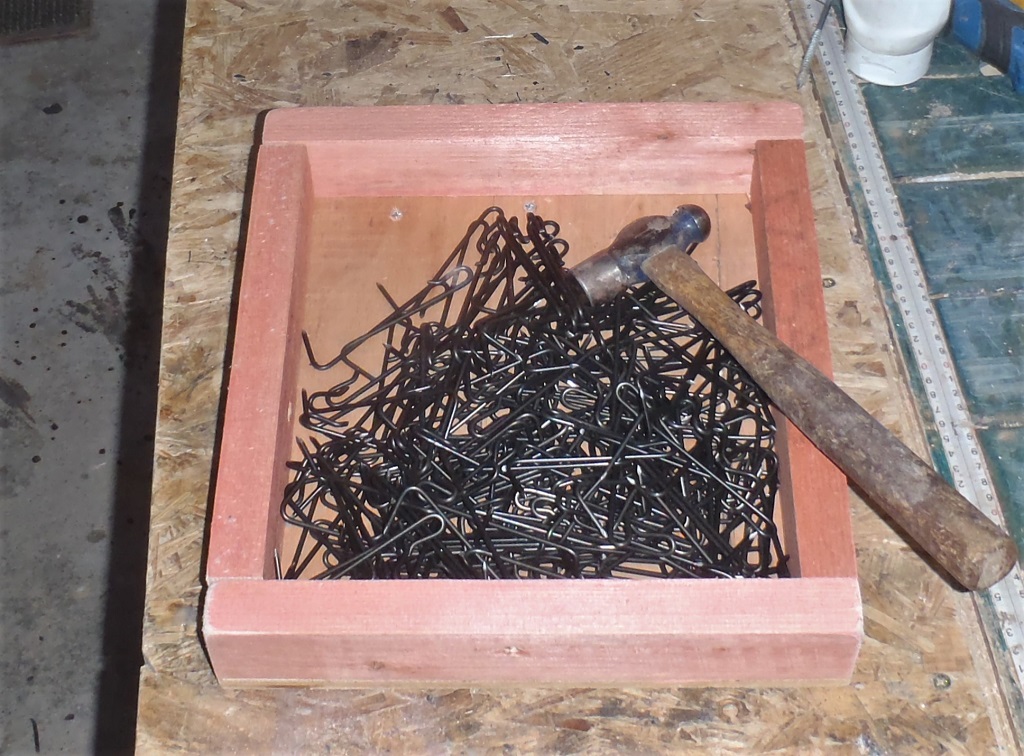
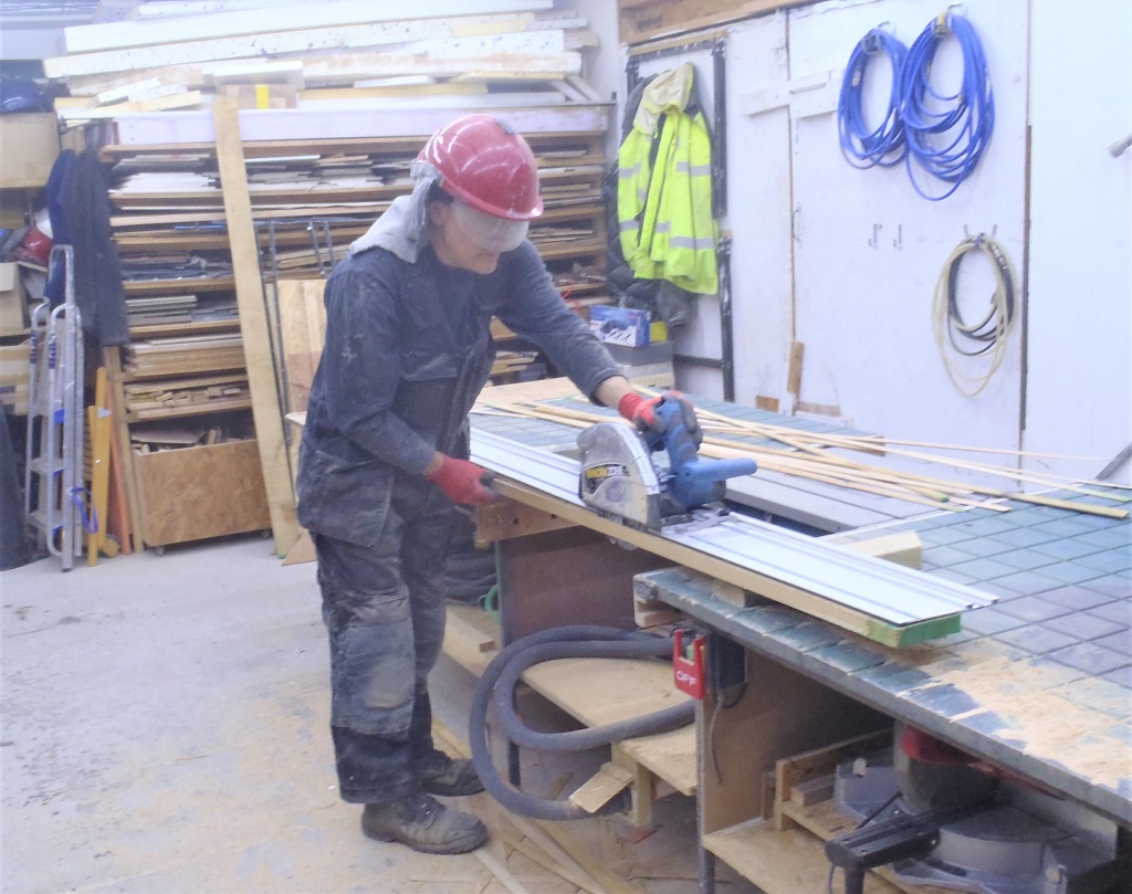
    After that, it was a case of getting into the practice of nailing our nails in for each row before putting in the next slates (thus avoiding discovering afterwards that we missed some nails!!) and also remembering to turn the slates upside down when using the guillotine too, because the guillotine works downwards and causes the bevelling edge effect as the blade explodes through the slate.

    We are learning as we go along!
    The next thing for us to learn, is doing the diagonal shaped slates when we interface to the hip edge. After having sneaked a training video on the net, we had that one sorted too and we were able to complete 5 rows before the end of the day.

    Slates Start Going Up!

    The-first-slates-1

    Slates Start Going Up!

    The-first-slates-2


    We continued on the next two days and doing three slates at a time for each row, working diagonally back towards the hip, this being the best compromise between doing more at once against having to lean over to far sideways (and slightly above) to nail in the next hooks and slide in the slates.
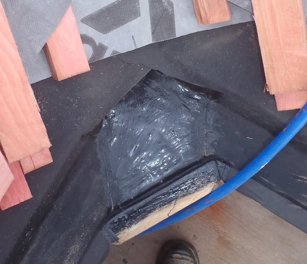
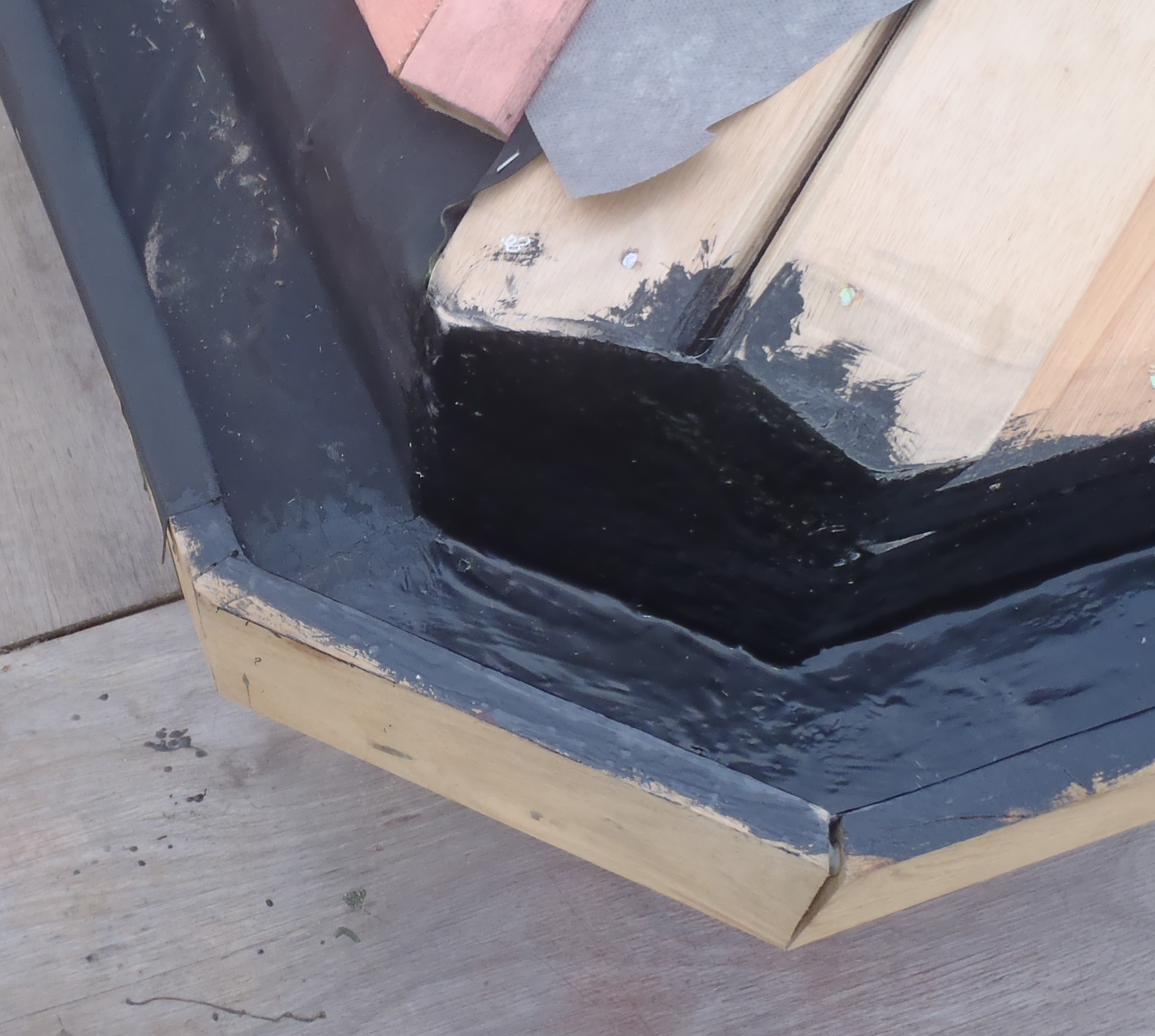
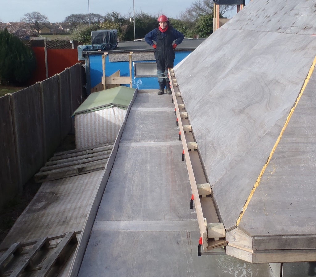
    When we reached the inside corner, at the bottom of the valley between the I and J roof slopes and had to spend some time there to sort out the metal mesh, to shape it , cut it and bend it, to cover up the corner of the gutters and the end of the fibre-glass trough. We then completed a total of 9 stripes.
    Slates Start Going Up!

    The-next-9-stripes-of-slates


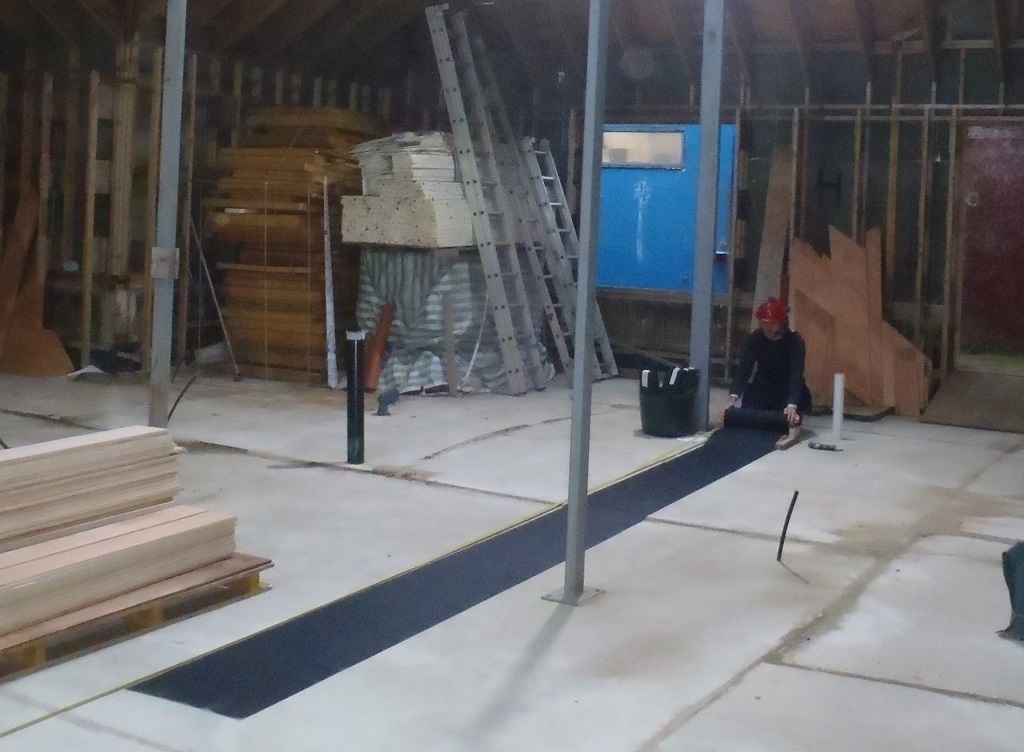
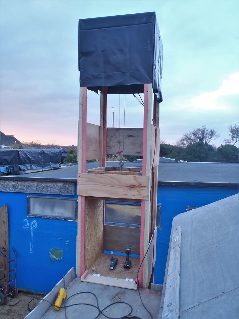
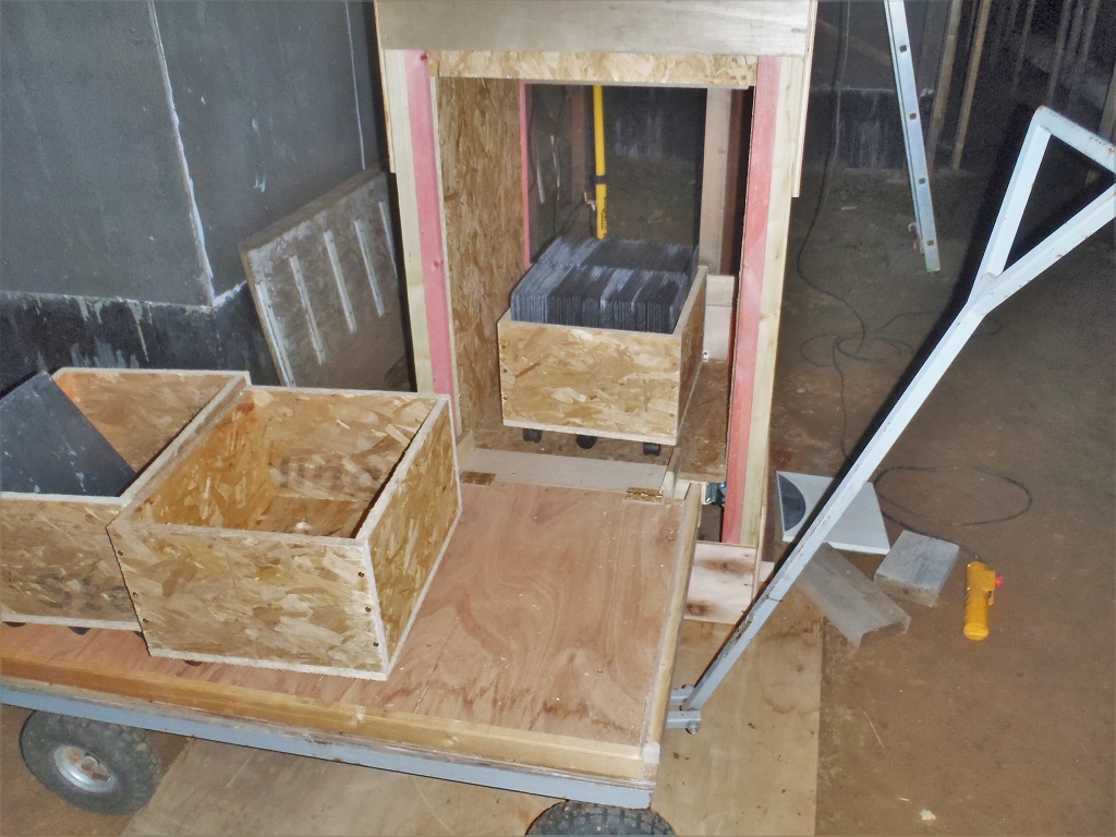
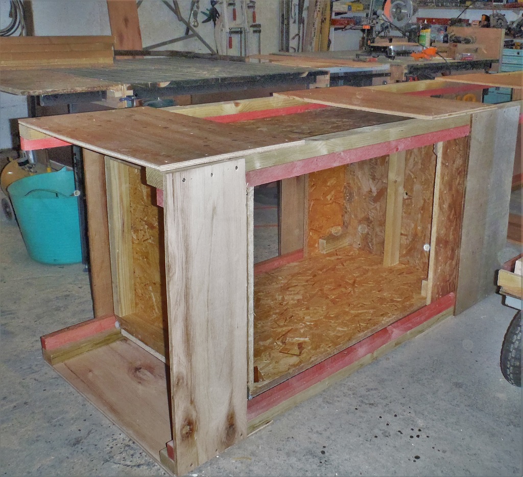
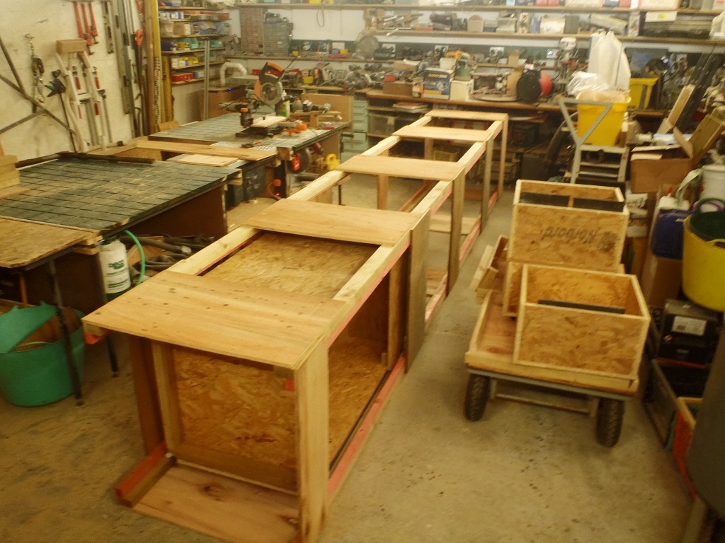
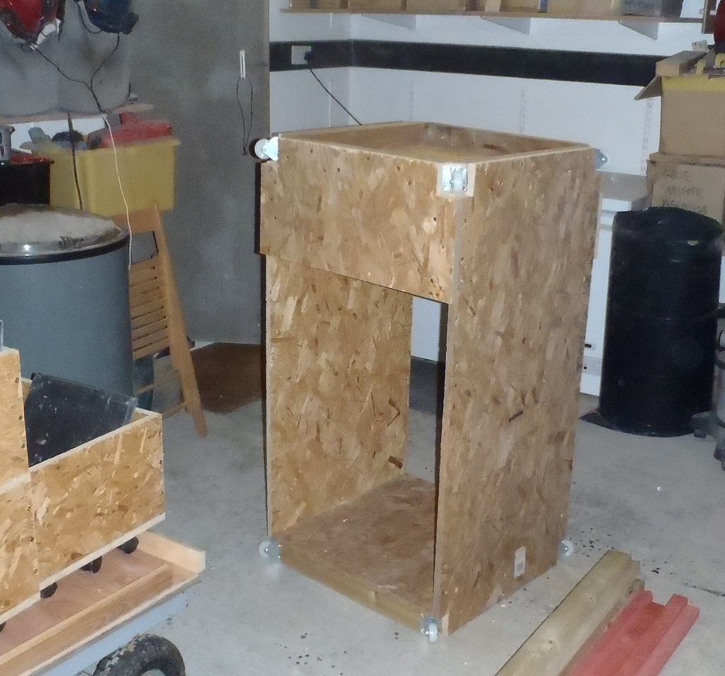
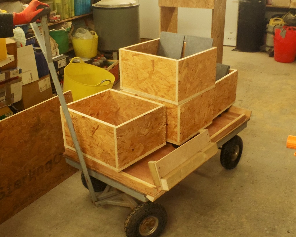
    Finally, on the last day, Saturday, we could work on installing the slates without pausing to cope with another challenge like a valley, we got about 300 slates up, we had to go and load up our three “boxes on wheels” (which hold about 110 slates each) with slates from the eleven crates waiting alongside our Loke.
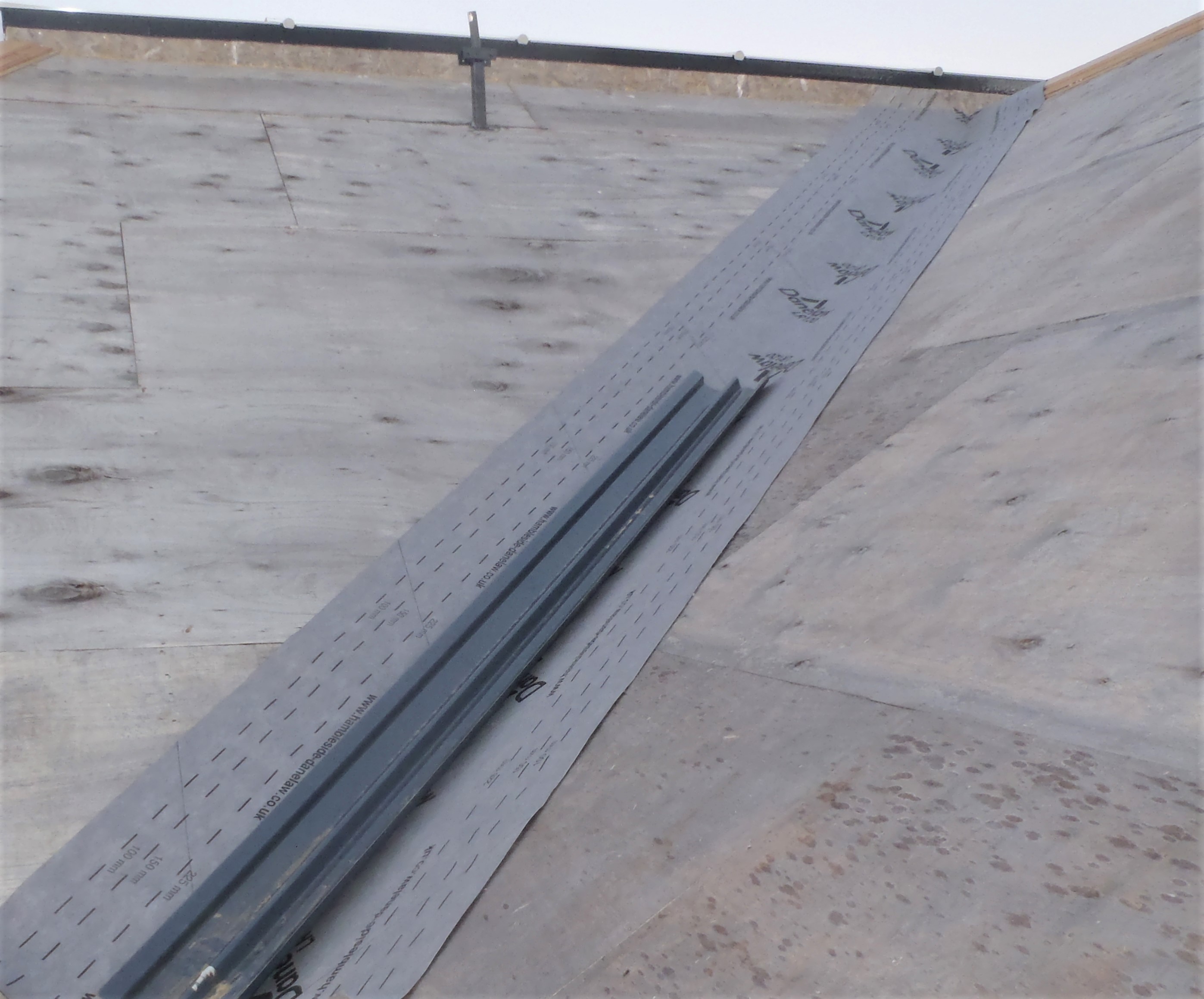
    We finished the day by installing the second fibre-glass trough section to join on to the first one. We are getting quicker and completed 15 stripes!
    Slates Start Going Up!

    The-next-15-stripes-of-slates


    We are about half way up and we will resume on Monday, weather permitting, and hopefully get the rest of the roof done by Tuesday. At which point, we will start on the J section at the bottom again!

  • Slate Cutting tool, Nail Containers and Slate Spacing Guides

    Today, following on from Saturday’s work, we designed and built a slate cutting guillotine with supporting stand which has rubbish collection built in.

    Slate Cutting tool, Nail Containers and Slate Spacing Guides

    Slate-cutting-guillotine-and-stand


    The guillotine sits on top of the box like container and there are standard measured marks to help us repeatedly slice certain slates at various required sizes.
    The next piece of equipment we made, was a couple of containers to hold the various types of nails (the stainless steel slate hooks and two sizes of copper nails).
    Slate Cutting tool, Nail Containers and Slate Spacing Guides

    Box-of-slate-hooks

    Slate Cutting tool, Nail Containers and Slate Spacing Guides

    Box-of-copper-nails-with-tool-storage


    Next item were two templates to guide us to align the slates at the required 204mm spacing, made using a 38mm wide batten with nails hammered in at the correct distances.
    Slate Cutting tool, Nail Containers and Slate Spacing Guides

    Slate-spacing-marking-sticks


    Finally, the second guide template was a metal affair with notches at the nailing points, again at the 204mm spacing but also marked are the half way points (the 102mm distance) between the notches, to allow us to align to the chalk line on the tile battens.
    Slate Cutting tool, Nail Containers and Slate Spacing Guides

    SLate-hook-fixing-guide


    Hopefully these pieces of equipment will provide consistency, ease of getting the job done and achieve a neat finishing touch to our roof. We now need to have good weather!!

  • Rubber Liner Installed in Gutters and Tiling Battens Started

    Here is a summary of our work for the last 10 days ..
    Using glass fibre and black resin, we sealed the complex downpipe channel three way intersection plus the two outer corners too. We did this to avoid the complicated task of laying the rubber membrane lining the gutters to go around the odd shapes of the corners and joining together the two incoming gutters (off the I and J sections of the roof). Then we glued in two separate straight strips of the rubber membrane, along the bulk of the gutters and sealed the ends onto the glass-fibre surfaces with contact adhesive.

    Rubber Liner Installed in Gutters and Tiling Battens Started

    Fibreglass-and-rubber-on-inside-corner-IJ

    Rubber Liner Installed in Gutters and Tiling Battens Started

    Fibreglass-and-rubber-on-outside-corner-JK


    The first strip of the breathable membrane we put on the roof is for the valley as this is always the lowest point for any water to run downhill so we laid down a metre wide strip with stainless steel staples.
    Rubber Liner Installed in Gutters and Tiling Battens Started

    Membrane-in-the-valley

    Next things we had to analyse and test, was the valley trough (a moulded fibre-glass constructed object) that needs to fit underneath the slates, to catch all the rain water flowing down the slope into the valley. It is a deliberate method of allowing the water to “leak” pass the end of the slates and collect together and be diverted in a channel. For this reason, the battens needed to be spaced apart so it is fully supporting the trough on the bottom, and then supporting the two outer edges on the wider tile batten.
    We made a test assembly on another valley on the roof first and worked out that three 38mm wide battens can be placed together (with a gap of 38mm between the inner single batten and the two outer battens) on each side of the valley, with a gap measuring 130mm wide between them. Then a 50mm battens is placed on top of the 2 outer battens to hold the edge of the trough.

    Rubber Liner Installed in Gutters and Tiling Battens Started

    Test-fitting-valley-trough


    Using our research, we proceeded to screw full length battens (4.5metres long) into place, on top of the breathable membrane already there, going up the I-J valley and then we doubled back on ourselves putting 90mm nails into the underlying rafters to provide a strong secured fixing.
    It now follows that we can start on the task of mounting all the tile battens on to the roof. The breathable membrane goes on first, going flat on to the roof boards, starting the first line, overlapping the lower rubber membrane and running over the Hip and Valley ends. The membrane was held into place with the vertical lines of battens, in short segments that stop just before the top edge (To allow the next piece of membrane to overlap). Then the horizontal tile battens were nailed into place at regular spacing of 112mm apart, so that a slate will sit across three rows of battens and hook onto the hanging nail off the third line.
    Rubber Liner Installed in Gutters and Tiling Battens Started

    Slate-layers


    We managed to get about 20 rows on the I roof and about 16 rows on the J roof sections, just about half way up the slope.
    Rubber Liner Installed in Gutters and Tiling Battens Started

    Battening-started-on-I

    Rubber Liner Installed in Gutters and Tiling Battens Started

    Battening-started-on-J


    On Monday, in the afternoon, we will resume this task of more wooden battens and probably have it all complete by Tuesday.

    We are learning the techniques and methods needed on this section of roofing, and will be getting better and quicker at it as we progress!

  • Installed the First Three Sections of the Gutters

    Over the last 10 days or so (with interruptions), we had installed the new Oak timber pieces to form the Guttering for the roof sections I, J and K.

    Installed the First Three Sections of the Gutters

    Gutter-structure-on-I-J-finished


    We carefully measured each section so the base board overlapped the upright pieces in an even way, getting the angles correct for the outside corners (needing approximately a 22.5° angles) and for the joining to the Downpipe channels (needing a 45° angle). We decided that we would put on a much thicker and taller piece of Oak timber to cover up the end of the Downpipe Channels.
    Installed the First Three Sections of the Gutters

    Gutter-inside-corner-cover


    Then using two homemade metal scrapers to spread out the special bulk-filling PU glue, one for the 19mm slot in the Fascia board (with little notches to ensure enough glue is left behind) and the other scraper for the multi-finger tongue and groove joints in the base board and the upright pieces. We used lots of clamps to squeeze the joint nice and tight but we also had spacer blocks inside the guttering to make sure we didn’t bend the vertical fronts inwards.
    Installed the First Three Sections of the Gutters

    Gutter-structure-on-K-finished


    These Gutters being completed now allows us to start work on the roof itself, preparing it for the battens and breathable membranes etc. That will start tomorrow.

  • Processing Oak Timber to produce Guttering pieces

    These last few weeks since the start of the year (January 2019), we have been processing lots of Oak Timber planks and producing finished pieces to build the Guttering System for the roof.

    The Track Saw

    We took 85 planks off our Oak Storage rack, these being a nominal 27mm thick by 2000mm long and selecting them to have a width from 110mm to 160mm wide. We needed to plane down all 85 planks to end up with 100mm wide and 19mm thick. It was the case of using our new circular track saw to slice a straight edge and then using this new edge, slice the excess width off to produce a consistent 105mm width planks with the bench saw.

    Processing Oak Timber to produce Guttering pieces

    Starting-gutter-making-by-straightening-one-edge

    The Planer

    Then our planer, with its two extension tables, took over the job to clean and flatten one flat side before all pieces going through the thickener mode of the planer to clean the other side and generate 21mm thick pieces. We stopped at 21mm thick, as the finish surface was very good so no need to keep going to the target 19mm. The final step was to clean the two edges and passing it through the thickener process to make a set of clean pieces, all 100mm wide.

    Processing Oak Timber to produce Guttering pieces

    Gutter-Planks-ready-for-shaping-

    The Router

    The 85 clean pieces were then split into two piles, the Base board (of the gutters) and the vertical uprights. We needed more consistent and longer ones for the base boards (a total of 43 full length 2metre pieces). The remaining, made up of 34 full length pieces and a collection of random lengths where we had to cut some planks up because they had more twist and warp down the length (to minimise wastage during the planing process).
    The first job with the router was to cut tongue and groove joints in both the base boards and the upright pieces. These are made up of four small “fingers”, located on the edge of the base board and on the lower side of the upright pieces so they come together and lock into a right-angle combined object. Then the upright pieces had a 45degree slope trimmed on the bottom edge so it provides a neat corner to the gutters. The final step was to trim a 10mm strip off the back of the base boards to provide a 19mm thick “tongue” that will slot into the Fascia boards.

    The Cap and Covering Strips

    Using the left over pieces from the earlier slicing of the wider planks, and more from our old left-over pile of strips in storage, we then produced lots of thin strips of Oak pieces, one size for capping the Upright sections of the guttering (designed to clamp and hold down the rubber liner and wire mesh), measuring 30mm wide by 10mm thick with all edges trimmed with a small 45degree angles. The second set of strips is for covering up the vertical and horizontal joints in the gutters, to disguise them. These Covers are a little bigger, measuring 35mm wide by 12mm thick, but only the front facing edges having been trimmed with the 45degree angles.

    Processing Oak Timber to produce Guttering pieces

    Pile-of-gutter-parts

    Processing Oak Timber to produce Guttering pieces

    Gutter-part-shapes

    Processing Oak Timber to produce Guttering pieces

    How-all-the-gutter-parts-go-together


    We have finished producing this set of Oak timber pieces for the guttering around the roof but only with the experience of installing the gutters will show us if we have generated enough wood to complete the whole circuit. It is not difficult to make some more, we do have some spare oak planks in storage.

  • Rubber Strips for Hips and Ridges Done and Metal Mesh Dispenser Coming Together

    We continued with the task of slicing up the wider rolls (four of them) into a little bit narrower width (380mm because we are using narrower slates than we envisaged months ago when we bought the rubber), using our dispenser with the razor blade as the cutting tool. But we discovered that the rubber material had too much flex in it to keep it straight and it wobbled side to side and made a ragged edge, especially after pulling out longer pieces. So we had a think .. and decided to replace the razor blade attachment with a battery powered scissors instead.

    Rubber Strips for Hips and Ridges Done and Metal Mesh Dispenser Coming Together

    Rubber-slicing-tool


    It worked much better but it was still awkward in trying to handle the rubber material and we ended up getting a third pair of hands to help to help roll up the cut rubber – we needed 1 person to unroll (the rubber is firmly ‘stuck’ on the roll) and 2 to re-roll (1 for each strip).
    We now have a trug full of 15 lengths of rubber strips, for the hips and ridges, alongside another 2 trugs of similar pieces but for the guttering.
    Rubber Strips for Hips and Ridges Done and Metal Mesh Dispenser Coming Together

    Trug-full-of-rubber-strips

    So that’s that job done so everything was dismantled and we started making the next dispenser, this time for the roll of the metal mesh. This metal mesh is for covering the gutters to keep out large items like leaves, moss and other rubbish blown on the wind.
    The mesh is a grid with 5mm spacings and the roll (being 920mm wide) will be chopped up into 300mm lengths and we are planning to use a guillotine like mechanism to cut the mesh. We will find out later on whether it will work or not .. time will tell!

  • Dispenser and Cutter for Rolls of Rubber membrane

    Today, we made a dispenser to hold a roll of rubber membrane (20m long strips 500mm wide wrapped on a cardboard tube) so we could easily unroll each roll of rubber and cut them to the required lengths. We had a list of 16 numbers, optimised to minimise wastage off these 20m rolls.

    Cutting-the-Rubber-for-gutters-to-length

    Cutting-the-Rubber-for-gutters-to-length


    We now have a pile of cut pieces ranging from 1.4m to 10.2m long, ready to be inserted into the guttering when we get to assemble each section around the house.
    We then modified the dispenser by adding a cutting module, positioned at 380mm from one edge so we can produce a narrower strip of rubber for protecting the hip and ridge lines. The cutting module was made by sandwiching a classic razor blade in between two strip of battens and then screwed down to the upper layer of the cement board.
    Dispenser and Cutter for Rolls of Rubber membrane

    Rubber-slitting-machine


    Even a razor blade struggled to cut the rubber membrane when we tried to slide it through the thin slot. But we realised that if one manually cut a short distance first, it started slicing fairly easily afterwards.
    On Monday, we will slice the remaining four rolls and cut a further 15 lengths (10 hips, 5 ridges).

  • Lift Shaft Installed and All Working

    Today, we took the opportunity of the fine sunny but cold weather to take our Lift Shaft outside and install it against the walkway platform running around the back of the building. It was positioned against the start of the “I” section of the roof, mounted on a 8feet by 4feet sheet plywood. We also anchored it up at the top of the nearest leg of the platform to ensure that it won’t get blown over in high winds or topple with heavy loads inside it.

    Lift Shaft Installed and All Working

    Complete-Slate-Lift

    Lift Shaft Installed and All Working

    Lift-at-the-Bottom

    Lift Shaft Installed and All Working

    Lift-at-the-top


    We had to slide the cargo cage up inside the Lift Shaft while it was lying on its back, entering from the bottom. Then push the whole thing upright by lifting at the other end (the top end) and slowly walk it gradually upright. It was also anchored at the bottom to the plywood base sheet too.
    We then hooked up the hoist motor at the top of the shaft using a metal pole and unwound the cable down to the cage. The final job was to mount on a second ramp on the other side of the cage, the side facing the platform walkway so we can trundle our dolly trolleys off. We tested the capabilities of the whole system by first loading several heavy concrete blocks into the cargo cage (about 75kg of load) and ran it up and down several times.
    Then we went to our slate storage area and loaded up one of our dolly trolleys full of slate tiles, we managed to put in two rows of 60 slates. We took that back again using our modified flat-bed trolley and loaded it into the cage. We weighed this and the cage on a bathroom scales and it came to just short of 150kg and the cage being about 40kg itself which leaves about 110kg for the box of slates. This latest load test was handled just fine!
    Lift Shaft Installed and All Working

    Loaded-dolley-in-lift

    That is the basic lifting system all done, mechanically speaking at least, but we have ordered some electrical switches, push buttons, limit switches (to detect the position of the cargo cage) and relays plus a micro-controller (tiny computer) chip to join all these pieces with some logic to achieve a much better system of having the ability to push a button to send it up and automatically stopping at the top, and do the same with another button at the top to send it down again. It will have other safety features like the ramp must be folded up and secured before the lift can start moving.

  • Lift Shaft Built

    Today, we created the Lift Shaft to take our box on wire up and down. It measures 730mm by 760mm (internal measurement of 680mm square, the size of the cargo cage) and it is nearly 5metres (16feet) long, or rather tall when it is standing up.

    Lift Shaft Built

    Lift-cage-in-Shaft

    Lift Shaft Built

    The-16-foot-lift-shaft


    We also created the support framework to hold the metal bar which in turn is holding in place the electric hoist.
    And finally, a little sloping roof installed at the top end and we will wrap some heavy duty plastic to protect the motor, electrical wiring and control boxes from rain water.
    Tomorrow, we will man-handle it outside and rotate it upright on to a flat base to anchor it, slide it against the platform walkway and make any final adjustments including putting on the second ramp at the top.

  • Building a Lift Mechanism to Raise our Slates

    Today, we started building various pieces of equipment to help us lift our Slate tiles up to our working platform. We need a lifting mechanism to raise our dolly trolley load of slates so we created a cage measuring 2feet square by 4feet tall, with castor wheels in each corner, both at the bottom and the top.

    Building a Lift Mechanism to Raise our Slates

    Slate-lift-cage


    The cage will be connected from the middle point, via a steel wire, to our electric hoist and controlled by several push buttons and the cage will move up and down inside a framework to keep the cage straight and stop it twisting around or jamming up.
    The other task was to adapt our medium sized flatbed trolley so it can transport three of our dolly boxes to and from the crates of slates, including a little ramp that will bridge the gap to the cage in our lift mechanism.
    Building a Lift Mechanism to Raise our Slates

    Small-trolley-modified-to-carry-slate-dollys


    Tomorrow, we will build the lift shaft, all 16feet of it!!