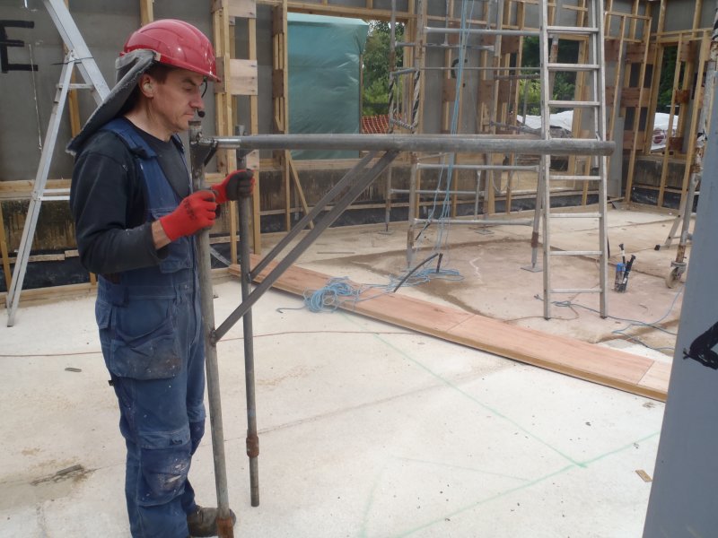
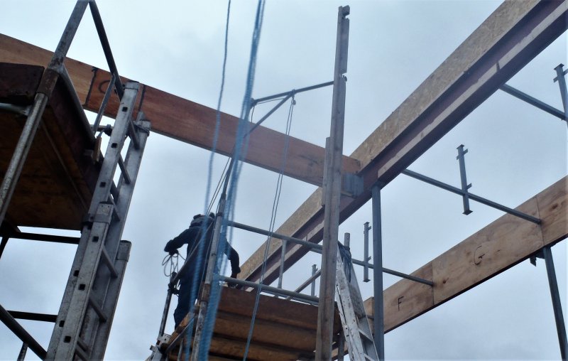
While we waited for the rain to stop, we rescued the castor wheels from some old tool object which served in the past to help move around the massive steel I-Beams. They were unbolted and set ready for fixing on the scaffolding feet, which we went out at the point the rain was almost stopped and took the flat metal feet off the scaffolding tower. Then, we unscrewed the fat pipe section off the threaded rod and the flat plate (we really had trouble with the fourth one! It was so badly rusted inside that it took us an hour of bashing, blow torching, oiling and everything else under the sun to get the damn nut to move! Eek!). Then each plate (10mm thick by 180mm square) had four holes drilled into them and had the castor wheel bolted on, we finished only three of the four before we stopped for the day, .
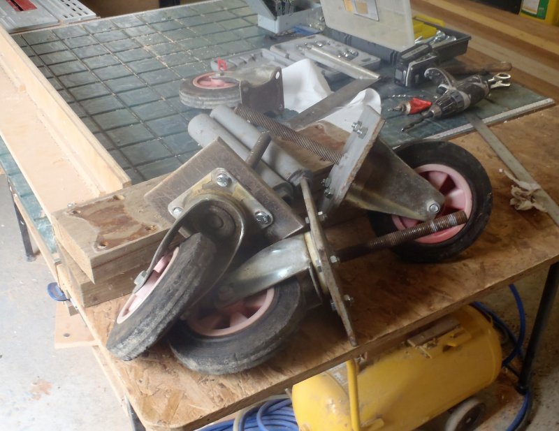
Casters-for-scafold-tower
Tomorrow or Saturday, we will do the final fourth foot and then put the new feet with wheels back on the scaffolding tower and this will allow us to easily move this second tower around, just like the other one!