Month: August 2017

  • Rafter HI Is Mounted!

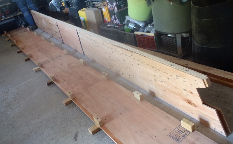
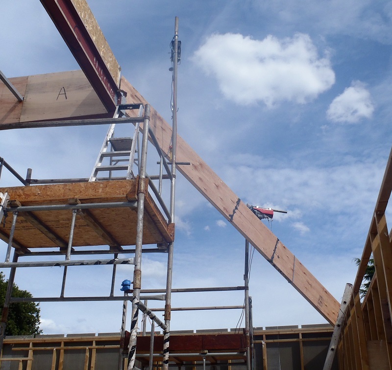
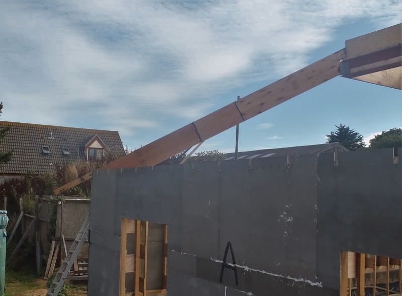
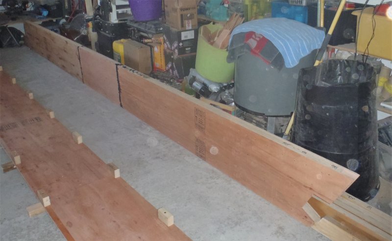
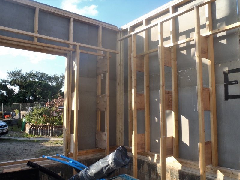
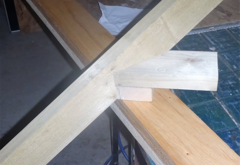
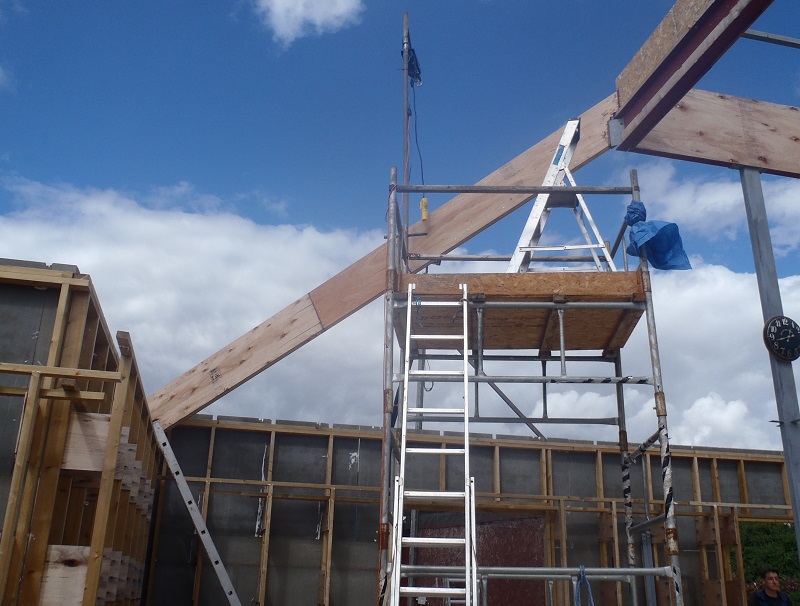
    This morning, we took out the completed rafter we had glued and nailed yesterday out to get it up into the HI corner of the building (Bedroom 3). We had a pile of excess timber material plus the other corner legs, all covered up so we had to try a different method of lifting the rafter up. We thought we would try lifting it using just the one winch motor, the one on the very tall and much stronger support arm. Actually, it turned out to be relatively easy to control, to lift the sticking out end up and over the wall first and swing the rest of the rafter back up and above the steel I-Beam and bring it down into position quite easily. It slid into place without fuss so that was that. We did our usual of gluing the corner leg into the two cement boards and screw them all together. Then glued the webbing and bird’s mouth all over the place and plus the metal bracket and the kerb at the other end of the rafter. The whole lot then was reinserted back into position and nails hammered into the side of the metal bracket and screws at the wall end to fix things down while we waited for the glue to set.

    Rafter-HI-Installed

    Rafter-HI-Installed


    And that was it! Using the single winch might turn out to be a good discovery and may speed up the operation of getting all the rafters up and into position. We will see. The next job with these special LVL Rafters is to make the metal bracing bracket that will join and support both the K Ridge and O Ridge together. After those are done, there would be only 7 more diagonal rafters (4 Hips and 3 Valleys) to go and we would be finished with these complicated and specialised elements of our roof!

  • EH Hip Rafters Goes Up and HI Rafter is Built

    Just for this morning, before we have other commitments and before the rain comes, we went outside with our completed EH Hip Rafter and installed it into place (the Utility Room corner). It was a fairly easy operation as this rafter doesn’t have a sticking out eve piece. We first glue and screwed the vertical leg into the corner and screwed the two outside cement boards hard back onto the leg. This provided support to allow us to use a crowbar to push the rafter back up towards the steel I-Beam and the Kerb as our tests revealed that we needed to shift the rafter back again after being dropped into the metal bracket at the top. Then, the two ends of the rafter was glued and finally nailed into place in the metal bracket to lock it tight while the glue sets.

    Rafter-EH-Installed

    Rafter-EH-Installed


    After tidying up the towers and covering up the winch motors to protect against the weather, we went back in the workshop to spend the last hour to assemble our 3rd rafter in this set we have been doing these last week or so. That was also a fairly easy job as we had the pieces all ready for the task, so with a quick vacuum everywhere, we glued and nailed the HI Rafter so it can dry overnight before also being installed.
    Rafter-HI-made

    Rafter-HI-made


    Tomorrow, we will put up this third rafter and then start the next job of preparing everything to make a set of metal bracing parts for the K and O Ridge sections on the two back extensions.

  • Rafters EH and HI Are Progressing Very Well

    This morning, we got down to putting the finishing touches to the materials that form the EH Hip diagonal Rafter. All the webbing plywood pieces and both the top and bottom LVL flanges were sanded. Then we moved on to the HI Rafter, we went outside to measure the top flange which turned out to be 5635mm, so we cut in the bird’s mouth and sliced the inverted arrow cut-out at the other end at that measurement. We tested this piece outside again and all is well. We then cut the bottom flange to size.
    Back in the workshop, we vacuumed everything to get rid of the dust and then started building up the layers of the EH rafter in the template and glued and nailed the whole lot together, on both sides, of course not forgetting to insert the polystyrene foam pieces too.

    Rafter-EH-Built

    Rafter-EH-Built


    That concludes the day’s work, but first thing in the morning, we will assemble the other rafter, the HI one, and get that one all glued and nailed so it can be drying while we take outside the EH rafter and mount it into place, and on Saturday, we will mount up the HI rafter and we would finally have done those three similar rafters – At Last!

  • Hooray! The PA Hip Rafter is Up!

    This morning, under a very nice sunny blue sky, we took out our completed PA Hip Rafter from the workshop to the building site, and after positioning the towers into place and trying 3 times to lift it up, finally made it to get it into place just before lunch!

    Rafter-PA-lifted-into-place

    Rafter-PA-lifted-into-place


    The trouble was that this rafter has a long sticking out bit that forms the Eves of the roof and goes out to the facia board and the guttering. This meant that we couldn’t lift the beam high enough one way and ran out of lifting wire on the winch before we could get it up. We finally shifted around one of the towers so it gave us more freedom of movement and also hit on the idea of lifting the other end (the end with the sticking out bit) first into the air so it overhung the wall entirely and this allowed the other end to come up and miss the obstacles on its way up! Phew! Oh yes, it fitted just fine!!
    After lunch, we smeared lots of glue all over the joints at both ends, up and down the leg and on around the top-plate of the wall. We wiggled and banged the rafter into the corner and inside the leg, and also slid into the metal bracket and against the kerb at the top too. All then was fixed down with nails and screws to hold it while the glue sets. Hooray At Last!!
    Rafter-PA-Installed

    Rafter-PA-Installed


    We carried on by moving the towers across to the next corner, the EH corner in the Utility Room and got our templates to measure the distance of the top flange which turns out to be 5570mm long. Inside the workshop, we took the correct LVL timber, sliced a flat bottom on one end and an angled cut upwards, and then measuring from that point, marked the timber at the other end at the 5570mm and drew the inverse arrow head with the tilt backwards. This end goes up and connects to the kerb of the Skylight. We carefully sawed out this inwards facing groove and took it outside to test it. Yes it fitted very nicely!
    Finally, we removed the excess plywood sections on all the strips, both for the EH rafter but also for the other corner, HI too. We transferred the pattern over from the HI webbing to the EH but in a mirror orientation so all our webbing is now ready for sanding and assembling into rafters tomorrow. We hopefully can get both of them glued and squeezed together and have them dry and ready to go either Friday or Saturday. Fingers Crossed!! Grin!

  • PA Rafter Now Glued and Nailed together

    We carried on today with the PA Hip LVL Rafter, making internal noggins (four of them, one at each end and two in the middle at the joints of the webbing). Everything then was vacuumed (the whole workshop, template, LVL timber, plywood webbing and everything else too!), but before we put the rafter together, we took the webbing and copied over the shapes of the cut-outs to the next set of webbing for the HI rafter we are going to do next. This rafter is the same in almost all ways as the PA rafter so we just copied over the pattern to save us some time.
    Next, we assembled the whole rafter and got our glue machine going and laid down a layer of glue along the LVL timber and noggings and sandwiched the plywood webbing on top, and went down both sides with the squeezer and nailed it tight together. We turned it over and then inserted the polystyrene foam pieces and vacuum it again and finally applied more glue to the this side of the LVL and again sandwiched the second webbing layer with the squeezer and then nailing that side together as well.

    Rafter-PA-Finished

    Rafter-PA-Finished


    While that was drying, we went outside to set the three corners we are doing, cutting to an exact length for each leg so it fitted just nice and tight between the foot-plate and top-plate!!
    Corner-post-in-place

    Corner-post-in-place


    Also, we put on the new wheels for the second scaffolding tower, after reducing the height down by one section so it can more easily fit under the diagonal rafter beams.
    Wheels-added-to-other-tower

    Wheels-added-to-other-tower


    Finally, to finished off the day, we sliced and trimmed the funny cut-away piece on the HI corner, removing a small vertical piece of the cement board, just like we did on the PA corner. Tomorrow, we will go out with our new PA rafter and see if it will fit in according to the plans! We have our fingers crossed ! Grin!

  • Half Day on Preparing the PA Rafter

    This afternoon, we carried on with sorting out what we need to do to make the PA Hip Rafter. All the surfaces are sanded (both the LVL flanges and plywood webbing) but we discovered that some of our plywood had a fault in the manufacturing process with the glue missing in the middle layer. It was a small section about 1 foot long and about 5 inches deep. We carefully looked at the other plywood strips and found three more. we never noticed this before and it is quite obvious! So we poured some glue inside the crack (forcing it open a bit more with a wedge) and then squashed it flat using large blocks of wood and half a dozen clamps. We did two strips today and will do the other two tomorrow.


    The next job was to cut away notches in the webbing at each ends so they can slide into place and keep clear of any obstacles like steel I-Beams and wall’s top-plates etc.
    Lastly, we need to vacuum all the pieces .. but we had an Incident!! The vacuum system suffered a major breakage! We accidentally blocked off the nozzle and suddenly there was a loud cracking sound and we turned everything off rather quickly!! We discovered that the wooden side of the box that holds the first major separator chamber has split right along the vertical edge and also the bottom horizontal edge too!! Wow! What sort of level of force would that need to do that kind of damage?!

    It was nearly the end of the day anyway, but we sorted out a temporary by-pass connection pipe (to go straight into the second filtration chamber and the motor unit)so we can still use the new vacuum system to clear up the dust before we glue all the pieces tomorrow. Phew!

  • Very Carefully Preparing PA Hip Rafter

    Today, we continued with preparing the LVL timber flanges for the first of the main corners of the roof, over the Great Room, in the corner where the P wall meets wall A, hence we called this rafter the PA Hip Rafter.
    We wanted to be very careful while cutting and slicing out the Bird’s Mouth notch, making sure the length of the top flange is as exact as possible, as because we have One and ONLY ONE of these LVL special timber so making any mistakes would mean buying another one (£40 and weeks of delay)!! We achieved the accuracy requirement, double checking and analysis of how the real world reflects against our computer drawings, by the help of another little template that plugged into the metal bracket up on the steel I-Beam. We could see where we had to remove sections of the webbing so it could hook over and get past the sticking out flanges of the steel I-Beam itself. We recognised that the corner point of the I-Beam needed to be sliced off too (about 15mm using a hacksaw and plenty of muscle!). Then, down on the PA corner, the cement board was sliced away to just allow the LVL 38mm wide timber to come through and also remove an angled section of the top-plate timber so that the Bird’s Mouth on the LVL timber will lock into place. So following this corner, we made another little block of wood with the correct slope sliced out on the bottom so it could sit and line up with the new cut-away section and provide exactly where the LVL timber will go.
    All this preparation work allowed us to measure the exact distance along the top flange of the rafter, all the way to the Kerb’s corner up on the I-Beam. This distance turned out to be 5600mm.
    This gave us a measure of confidence to commit ourselves to cutting the Bird’s Mouth and marking out the other end using this 560mm number. We wanted the LVL flange to fit neatly up against the Kerb’s corner, so it had to have an internal corner sliced out the end of the beam. We took back outside the LBL timber with the Bird’s Mouth and the markings, got it up into the corner and up onto the bracket and slid it into the template so we knew what height it should be. We double checked the markings to make sure it was looking good, so again we committed ourselves to cutting the excess wood off the end and slicing the funny inwards pointing angled groove and got it fitted just nice and tight!! Phew!
    Then back to workshop with our LVL timber again, and laid it down into our rafter template so we could position the bottom flange next to the top flange (the one we have been working on) and line everything up, double checking everything again, and then slicing the bottom flange to exactly the right size too!

    Rafter-PA-Top-end-and-Measuring-jig

    Rafter-PA-Top-end-and-Measuring-jig

    Rafter-PA-Birds-mouth

    Rafter-PA-Birds-mouth


    This pretty much was our day’s work – Phew! It is slow but we can’t make a mistake or it will costs us money and time and be very annoying too!! Nice and steady for these special diagonal LVL rafters around our roof. Thank goodness there are only 17 of them in total and we have done three of them so far, with the three we are working on now. Monday, we will carry on with the PA rafter and get it fitted into place and prove our methods and increase our confidence to do the other two similar Hip rafters for the other two main corners.

  • Vacuum System Construction Continues

    These last two days have seen more work on the new Vacuum System for the workshop. Yesterday saw the electrical wiring, switches and sockets being fitted to the machine module (housing the two motor units). The idea is to have a high current 32Amp lead coming from the utility rail to enter into the box, split into two 13Amps lines. One for the vacuum motors and the other line, via a socket on the back of the unit, going onto to the work table, next to the vacuum pipe.


    A rotating switch (taken from an old fan heater) provides the means to switch one or both motors into action, to provide two levels of vacuum power. This is not exactly correct way to describe this as the level of the vacuum doesn’t change when both motors are running, but what actually happens is, there is a great increase in air flow and this feels as if it has a higher vacuum power. It is more true to say that it is a case of how fast the air moves up through the pipes and the faster the air gets “sucked” up the pipe, the broader the effect of materials being caught and dragged along with the air and disappearing up the pipe!
    One result of all the unit being connected together (the vortex separator chamber and motor unit), is the noise! The motor noise is not so bad and we could reduce the noise with some wadding inside the motor unit, but the loudest noise was coming from the Vortex Separator chamber! It was very loud, like a tornado .. which is what it is!! We probably will build a box around the vortex unit and put more wadding inside to keep some of the noise in – We Hope!
    The last job of the day was to electrically connect the new “second” line to the work table so we can immediately continue to make use of the equipment in and around the table. The final task left to do, is the vacuum 50mm hard plastic pipe that comes across the floor from the box, and redesigning the existing pipework (this providing the connections to various equipment for collecting the saw dust and the like) so everything is joined up and ready to Go Go Go!

  • LVL Hip Rafters Preparation Continues, Light Bulb Moment and Update to Drawing!

    After we finished off doing the wheels for the scaffolding tower, we continued preparing the bits and pieces for constructing the LVL Hip Rafters for the PA, EH and HI corners. We sliced a 26.6° wedge off the ends of 12 strips of the plywood webbing, making sure that the better side was towards the gluing direction (I.e. facing inwards). Then, the next job was to sort out the LVL timbers and labeled them so each one it is now determined for the correct role, three longer pieces for the top flanges and the three other one for the bottom flanges.
    Next is to take the two top flanges that are going to have the bird mouths cut into them and start marking out the complicated shape of the cut-away section. We decided to do a practice run on a spare bit of 89mm CLS timber rather than the precious LVL timber. So we sawed the bulk material away and used a mixture of our wiggle saw (officially called an oscillating multi-tool, but what a mouth full!) and hammer & chisel to carve out the concave angled groove so it can sit tight over and on the outer corner of the top plate (see pictures below).

    Corner-birdsmouth-cut

    Corner-birdsmouth-cut

    Corner-birdsmouth-cut-on-corner-piece

    Corner-birdsmouth-cut-on-corner-piece


    While we were looking at this complicated cut-away (double checking) on the computer, and also inspecting the actual Top-Plates on the walls in the corners of the house to make sure that we didn’t have missing timber which may meant a weaker joint (it turns out that all six affected corners were fine), we had a light-bulb moment! It suddenly it occurred to us that the pointed part of the corners on the top-plate could be removed to make a flat area for the rafter’s birds mouth to sit against flat .. WITHOUT any complicated inward groove! Phew!
    So the rest of the afternoon was spent on the computer to update the drawings so that all the six corners around the house will have regular ninety degree birds mouth cut-outs and instead, a measured and angled chunk is removed from each corner on the top-plate with just a good old plain handsaw and Hey Presto .. All will Comes Together Plain and Simple .. Nice and Strong .. Oh Phew .. Smile!
    On Saturday, we can proceed with a much relieved state of mind over these LVL Hip Rafters and get on with it much faster! Hooray!

  • Final Wheel Is Completed for Scaffolding Tower

    This morning, we finished off the fourth wheel by drilling the holes into the foot plate and bolting the wheel together to the foot. We then shortened down all the fatter metal pipe (this is the support pole that goes up inside the scaffolding leg and bolted down) so we can minimised any extra height we would put on the tower (we are wary of this factor because we need to move the towers around and have to slide underneath any rafters we may have put up), the new length of this pipe is 110mm.
    The fourth foot had its nut plate welded back onto the support pole and the threads were all heavily greased to avoid any further rusting problems!!
    These are now ready to be re-installed back onto the tower when we are ready to put up another completed rafter beam.