Category: Build Progress

  • Front Set Rafters Fitted and Two Ends Now Sliced!

    Today, we continued with the task of adjusting and fitting each individual rafter to fit smoothly both at the Ridge beam and at the outer rim edge too. Another 14 were done, this time along the front.
    After lunch, we started working on the two ends, cutting the ridge beam down so it is flushed against the last two front and back rafters but only cut down 65mm until reaching the last third layer which we don’t chop off. We decided that this third layer will have a sticking out ledge of 30mm, for the final three rafters to sit on. The easy rafter (the 90degrees one) was done, plus doing the shorter Rim pieces, fitting them into place doing butt joints with the outer Rim edges.

    Front Set Rafters Fitted and Two Ends Now Sliced!

    End-of-ridge-and-Rafter


    We finished off the day by starting to work on the Hip rafters, there are four of them, two at each ends. These hip rafters are angled at 10.5degrees instead of the 15degrees that all the other rafters are. Also these hip rafters have two little sloping sides on the top surface and these are also at the 10.5degrees angle.
    Front Set Rafters Fitted and Two Ends Now Sliced!

    First-Hip-rafter-started


    We will continue with that task on Friday but for tomorrow, we will sit down and order samples of various slates from different companies, along with a quoted price for the amount of tiles we would need.

  • Main Front and Back Skylight Rafters Created

    Today, we got on with the task of cutting and slicing the complicated shaped ends on all the rafters, each having five particular cuts in total, using our band saw and various templates to hold and guide the rafter pieces through the cutting process.

    Main Front and Back Skylight Rafters Created

    Rafter-ends-cut-1

    Main Front and Back Skylight Rafters Created

    Rafter-ends-cut-2


    Then these 25 rafters went outside to join the other two we had already made and placed into position (but not fully seated).
    Main Front and Back Skylight Rafters Created

    Rafters-in-place


    Each separate rafter will be sanded at both ends so it will sit neatly into their respected slots and form a smooth join all the way around.
    We got as far as adjusting all the rafters of the back set and tomorrow, we will do the front 14 rafters. Once those are done, we will tackle the two ends of the Skylight and get the hip framework sorted out, each end having two diagonal hip rafters plus one at 90 degrees, which all come together, along with the two rafters of the main section, to a single point up on the end of the ridge beam.

  • Rafters Cut to length and Templates started to Cut Complicated Ends

    This afternoon, we set up our chop saw on our work table to cut up 9 lengths of timber into 25 pieces to do all the front and back rafters of the Skylight. Each is 1273mm long on the edge (or 1299mm in actual wood length), because both ends have a 15degrees angle cut.

    Then we started building a template that will hold each of these rafter pieces, run along a fence guide on our band saw machine and slice a cut at a predetermined position and depth.

    Rafters Cut to length and Templates started to Cut Complicated Ends

    Rafter-end-cutting-jig


    We want to be able, repeatedly, to put in all the rafters to get exactly the same series of cuts so we end up with the same complicated shaped ends. There are a total of five cuts needed (three on one end and two on the other) so we will have to adjust and modify our template and fence guide five times over before we have it all done.
    Tomorrow, we will continue with this setup process and work on each of the five “methods” at a time to achieve our goal .. eventually – phew!

  • Lots of Small Steps of Progress With Skylight

    This blog entry is a summary of our patchy work on our Skylight for the whole week from Monday to Saturday. We had many interruptions to our work with various meetings and other activities that took us away from the construction of our Skylight.

    Monday

    We finished sorting out the timber pieces, putting them into a collection to form the two long edges of the skylight framework that will sit on top of the kerb wall on top of the roof. We made sure that the kink point had a start and end joint to allow for the half a degree bend and then got two more shorter lengths for the two ends, finishing off the complete circuit of the framework.

    In the late afternoon, we pulled up one of our tarpaulin sheets up underneath of the roof so we had a cover to catch the small mount of rain water dripping through the roof surface.

    Lots of Small Steps of Progress With Skylight

    A-bit-of-rain-deflection

    Tuesday

    We spent the day sawing the tops off the rim timber pieces, to form the gentle 15degrees slope. We put on additional wooden oak guide strip on the base of our mains powered circular saw and sliced each timber lengths (10 in total) on two trestle tables. It was slow but steady work, making sure we were keeping straight and also not overheating the saw’s motor either.

    Lots of Small Steps of Progress With Skylight

    Angled-top-on-rim-beams-1

    Lots of Small Steps of Progress With Skylight

    Angled-top-on-rim-beams-2


    We put the finished pieces back on the worktable and started on the task of marking all the positions of each slot on these rim edging lengths and it was only when we started marking up the ridge beam that we were unsure of whether the kink was accurate or not. We couldn’t get the right angle from the rim edge, up to the ridge beam, using our large framing square. It kept missing the point! We gave up for the day at this point so we could apply a fresh mind to the problem in the morning.

    Wednesday

    In the afternoon, we went up on the roof to reconfirm the measurements of the kerb and the offset from the straight line (using the string we had up there already) and also check the alignment of the steel poles along the middle that supports the ridge beam and the whole skylight structure. We then went back to our worktable back on the ground floor and redraw the outer lines using blue chalk powder instead of the red one we used last time, to snap a much better alignment. We verified that the new line was better by placing our large right angle framing square on this blue line and see it up on the ridge beam, and this time, we were actually getting the 13mm offset we have been looking for all the while! Phew Thanks goodness for that! We are now much more confident that the positions of both the slots in the rim edge timber and on the ridge beam are accurate and align up at right angles to each other.

    Thursday

    In the afternoon, a jig was created to allow us to use our mains powered circular saw to slice out a slot on the rim edging timber. The slot is 45mm wide so the jig allowed the saw to move sideways in small amount and do another cut. This repeats over again until the slot is riddled with many cuts.

    Friday

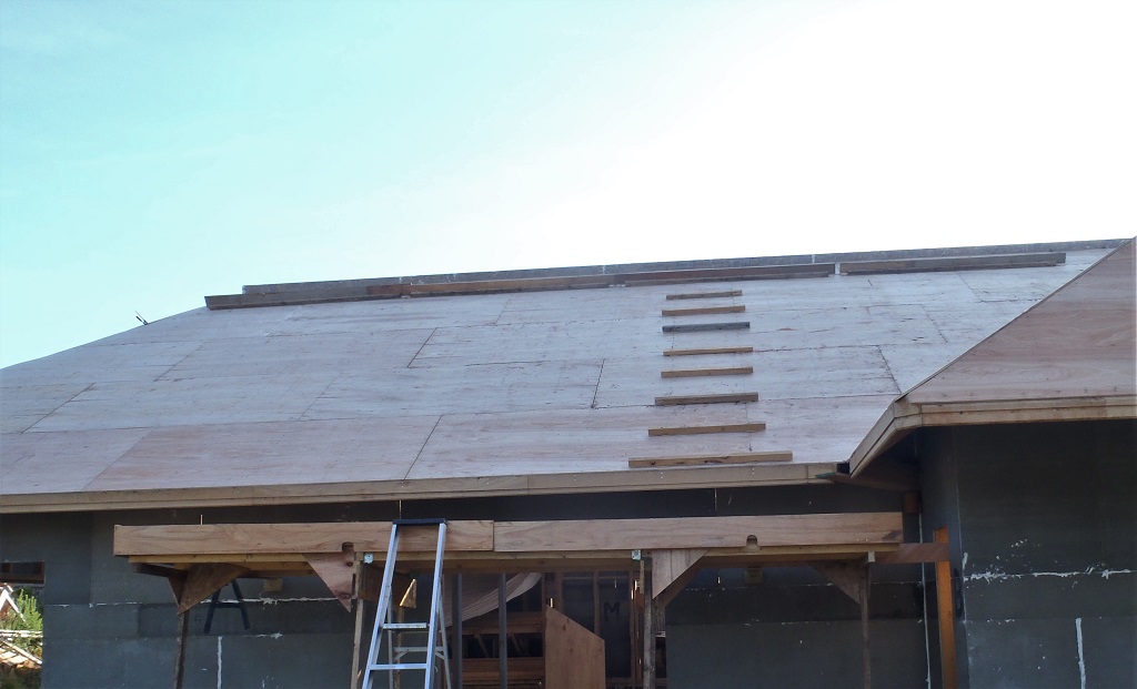
    We took our jig template and went around cutting 30 slots in total (13 on one side, 15 on the other side and one each on the two end).
    Then making a slight adjustment to our jig template, we then used our router machine with an extra long half inch wide cutter to clear out the rough bottoms of these 30 slots.

    Lots of Small Steps of Progress With Skylight

    Rafter-notches-in-rims-1

    Lots of Small Steps of Progress With Skylight

    Rafter-notches-in-rims-1


    Following another slight adjustment to our template, we proceeded to cut a shallow slot on the vertical faces of the ridge beam on both sides, exactly at the point where the rafter will be positioned. There were another 28 of those done. The two ends of the ridge beam will be sorted out later on.
    Lots of Small Steps of Progress With Skylight

    Rafters-notches-in-the-ridge-1

    Lots of Small Steps of Progress With Skylight

    Rafters-notches-in-the-ridge-2


    Saturday

    We created another jig template fitted to the mains powered electric circular saw, with a guide and the saw set at the 15 degrees angle. This allowed us to run the saw along the main ridge beam in both directions to slice a small amount of wood off the top edge to form two gentle sloping sides. This is where the top edge of all our glazing panes will meet in the middle. We also gave it a quick sand with a fine grade paper to remove the worse of the “hairy” surface.

    Lots of Small Steps of Progress With Skylight

    Angled-tops-cut-on-ridge


    Then we tidied up all the waste sawdust and thin slices of timber and cleared the workshop up so we can proceed in creating our heap of rafters. We made two prototype pieces, each being 1273mm long with 15 degree angled ends and then a bird mouth cut in the bottom end to make it fit into the rim edging and then cut a tenon at the top end of the rafter to fit into the taller but shallow slot on the ridge beam.
    Lots of Small Steps of Progress With Skylight

    First-two-rafters-made-1

    Lots of Small Steps of Progress With Skylight

    First-two-rafters-made-2


    We now want to repeat this again for another 28 more rafters so we are going to design some jigs and arrange the band saw so we can use our work table to support the 1300mm long timber pieces while slicing the shapes on each end of the rafter. That will be next week’s job.

  • Ridge Beam Done and Sorting of Edge and Rafters Continues

    This morning, we unclamped the second half of the ridge beam we created two days ago, and then pulled out our planer machine to run this and our first half of the ridge beam through the thicknessing operation. We did both vertical sides to reduce any variations in width, caused by the slightly different dimensions of the individual CLS timber layers, and also we removed excess material off the height, so at the end, we now have a Ridge Beam that is 60mm wide and 106mm high, all the way along all of both pieces.
    We pushed them together, on their overlapping joints and then drilled a single 10mm hole down through the three layers and pushed in a steel rod to lock them together so we can repeatedly pull them apart and put it back together again and achieve exactly the same position as before.

    Ridge Beam Done and Sorting of Edge and Rafters Continues

    Ridge-Layers-glue-joints-You-shouldnt-be-able-too-see-them

    Ridge Beam Done and Sorting of Edge and Rafters Continues

    Ridge-Center-Lap-joint

    Ridge Beam Done and Sorting of Edge and Rafters Continues

    Ridge-assembled-on-jig


    The next task was to sort out more timber, this time the treated 95mm by 45mm timber planks and picked out the straightest and least warped ones to form the outer edge of the framework of the Skylight. It was quite a long process as we needed to make sure we had also enough pieces that were straight for doing the rafters too. It was a case of deciding that a plank that did have a twist in it, could be cut down and avoid the twisted bit and end up with one almost straightened piece.
    Next week, we will continue this process of sorting it out and end up with a pile of rafter lengths and the outer rim pieces. We will then mark up all the positions of all the rafters and then start cutting and slicing slots to allow the rafters to lock into place.

  • New Ridge Beams Created

    Yesterday and today, we spent some time sorting out our pile of timber to bring out the 95mm by 45mm treated timber and reorganise the other timber pieces that we are not using straight away and have access to the 63mm CLS timber. We then picked out nine length’s of the 63mm CLS timber that were pretty straight and not warped.
    We got out our heavy duty planer machine and vacuum waste collecting unit, brought them out to our house so we could plane the nine lengths and have room to get each plank in and out of the machine (each plank is 4.8metres – 16feet long so you need 32 feet of space!). We sliced off about 1.5mm off to remove the rounded edges and then cut them into various length pieces so we could put together two sets to make the two separate halves of the ridge beam (one piece about 6 metres and the other one being 7 metres long) with a “finger” joint in the middle (overlapping by 150mm) in the mid-point.
    We also used our biscuit machine to help us align the three layers so that they all lock together and pull straight out any slight bow in the length.
    We managed to get one set all glued and fitted together, tightly clamped with a dozen clamps before the end of the day.
    Today, before the rain came, we dealt with the second set of timber pieces to create the other half of the ridge beam, doing all the biscuit joints and then gluing all three layers together and clamping it down tight.

    New Ridge Beams Created

    New-ridge-beam-made

    We covered it up with a tarpaulin to protect them (we moved the other beam we did yesterday to be near our new one) from drips from our roof.

    On Saturday, we will start processing all the other timber to make the rafters and the rim structure (using our 95mm by 45mm treated timber) and cutting and slicing various angles etc.

  • Analysis, Calculations, Ordering and Plan B!

    Yesterday, we have been doing the final calculations of how much aluminium glazing bars we will need to do our Skylight and fix all our pieces of glazing units we got up there. it comes to a total of nine 3m plus a further five 4.8m lengths of the standard rafter bars and a collection of the ridge bars, four various lengths from 3m to 4.8m. This design of this glazing system has a nice completely covering white anodised aluminium cap to deflect all the rain from entering any of the screw holes and reduces the chance of rain getting into the inner workings. They cost about £750 and should be here in a week or so.
    Then we carried on with the analysis of the Skylight ‘hole’ in the roof, trying to understand how it is situated and finally we got a handle on it at last. The rest of the day was spent on adjusting our ‘work table’ to reflect the reality, making a kink at the mid-point and skewing one end.
    Today, we levelled off the two long sides to avoid too many ‘up and down’ wobbles and then put up five Ridge posts ready to support the main central ridge beam. Just before lunch, we pulled out from our timber stockpile, the three pieces of timber (70mm thick and 93mm high – approximately 4inch by 3inch) we bought for the job .. but only to discover that two of them have warped badly, twisting down the length and bowing sideways too. Plus also, these planks have been cut from the middle of the tree and the tight rings have also buckled and distorted what was once a flat surface! O boy! We spent the afternoon analysing and talking about how we can cope with this, how to correct it if possible, bearing in mind that they are heavy and thick planks of timber. We were not confident that we could correct the twisting nature but what really stopped us, was the bulging grain (the rings) in the timber along the height of the wood and even though we could plane it using our planer machine, we were not sure whether it would just carry on distorting and twisting even more after we have made our Skylight module.

    Analysis, Calculations, Ordering and Plan B!

    Wonky-wood


    We decided that we couldn’t take the risk and went to investigate the availability of LVL timber, how long it would take to order and how much too. We would buy 78mm thick by 220mm high and about 7metres long but the first quote we got was a price of £120 for the timber and £95 for the delivery!! Eek! Ouch!
    It then occurred to us that we could make our own ridge beam by using three layers of 63mm wide CLS timber, planing down the thickness (to remove the rounded edges), stack them up on top of each other, overlapping the joints, removing any bad knots and gluing it all together and .. hey presto .. we would end up with our required Ridge Beam measuring 63mm wide by 105mm high! We will tackle that job tomorrow! And it would only cost about £40 in total for the timber and probably about £10 for the glue and it would only take about a day to do the work! So Much Cheaper, and much more satisfying! Phew!

  • Working “table” for Skylight is Almost Complete

    Yesterday and today, we carried on with the task of creating a “work table” to implement our design for our Skylight, all on the ground floor level instead of being 6metres (20feet) up on our roof!
    We used seven lengths of our untreated regularised 95mm by 45mm timber planks plus two off-cut pieces to make a framework of 16metres long by 2.5metres wide. This framework is held up on 1.2metres high legs, seven of them down each side and secured into place using lots of triangular plywood pieces to lock and stabilised the structure. Then the two lines were separated by a series of horizontal struts, also locked and screwed together using more triangular anchor pieces.

    Working

    Assembly-frame-started


    The whole structure was then confirmed to be right-angled at the ends and the long sides were straight (using a string) and then fixed and clamped to the three steel legs which provided a very strong stabilising support for the duration of our work.
    Lastly, we snapped a red chalk line down the length, positioned exactly 2.490metres apart which is going to be our finishing width of our Skylight.
    Working

    Straight-line-marked


    On Monday, we will go back on the roof and make sure the “real” Skylight is a proper right angle on both ends and measure the total length so we will know exactly where the ends are positioned, including where the nine steel cross ties are relatively located too, just to confirm against our drawings.

  • Preparation Continues ..

    We carried on with the preparation task of getting things tidied up and getting things ready for doing the Skylight. We put up the remaining foot-rails on the roof around the Skylight.

    Preparation Continues ..

    Second-roof-ladder-installed

    Preparation Continues ..

    Rest-of-the-Footrails-fitted


    We then started measuring the “hole” to see what reality is, compared with our drawings. There were variations in the width along the rectangular hole, measuring 2.5 metres in some spots but also 2.495 metres and 2.520 metres in other spots. We decided that we had better pull a string from corner to corner and see whether the sides of the Skylight’s kerb is straight or not. Alas, we discovered that we have a kink in the middle. The string shows that we have about a 45 mm offset on both sides, both leaning towards the swimming lane. Oh No! We will have to take everything apart and straighten out the steel I-Beams and the two middle steel legs!! Only Kidding! It seems that the transition from the heavier wider steel I-Beam to the lighter narrower I-Beam is where the kink is and of course, we hadn’t realised that we had this little kink when we originally mounted and positioned the steel legs in the first place. We calculated that this offset is equivalent to a 0.3° angle, calculating from the length of 7.49 metres against the 0.045 metres kink or about 1 in 200 ratio. We went back to our drawing to put in this kink and it doesn’t really make any different to the shape of the skylight and its glazing panes. We will just build the Skylight with the kink in it and everything should still fit quite comfortably.
    Tomorrow, we will start building the “work-table” down on the ground level inside the house so we can assemble the whole skylight module, test it and confirm our thinking about this kink.

  • Preparation Starts for the Construction of our Skylight

    We carried on with the tidying up and modifying of our old mobile platform to convert it into a fixed platform in the AB corner of the roof so we can have access to this side of the roof and the Skylight while we are working up on top of the roof.
    We also modified our foot rails to include an additional extra wide plywood strip to make the foot-rails more secure and somewhere we can put down tools as we work around the whole Skylight section down the middle of the roof. We have screwed down a ‘ladder’ on the roof to make getting up and down easy.

    Preparation Starts for the Construction of our Skylight

    Mobile-platform-transformed-and-roof-ladder-installed


    We will carry on the preparation work tomorrow and then start sorting out and building some trestle tables to support the framework of the Skylight module down at ground level so we can assemble (and test) it so we can check out the design and implementation of the various parts including the aluminium glazing bars. We need to make a series of trestle tables to hold up this framework (it being about 15 metres long and 2.5 metres wide), plus also to paint the timber and have it all ready for installation when we are happy.