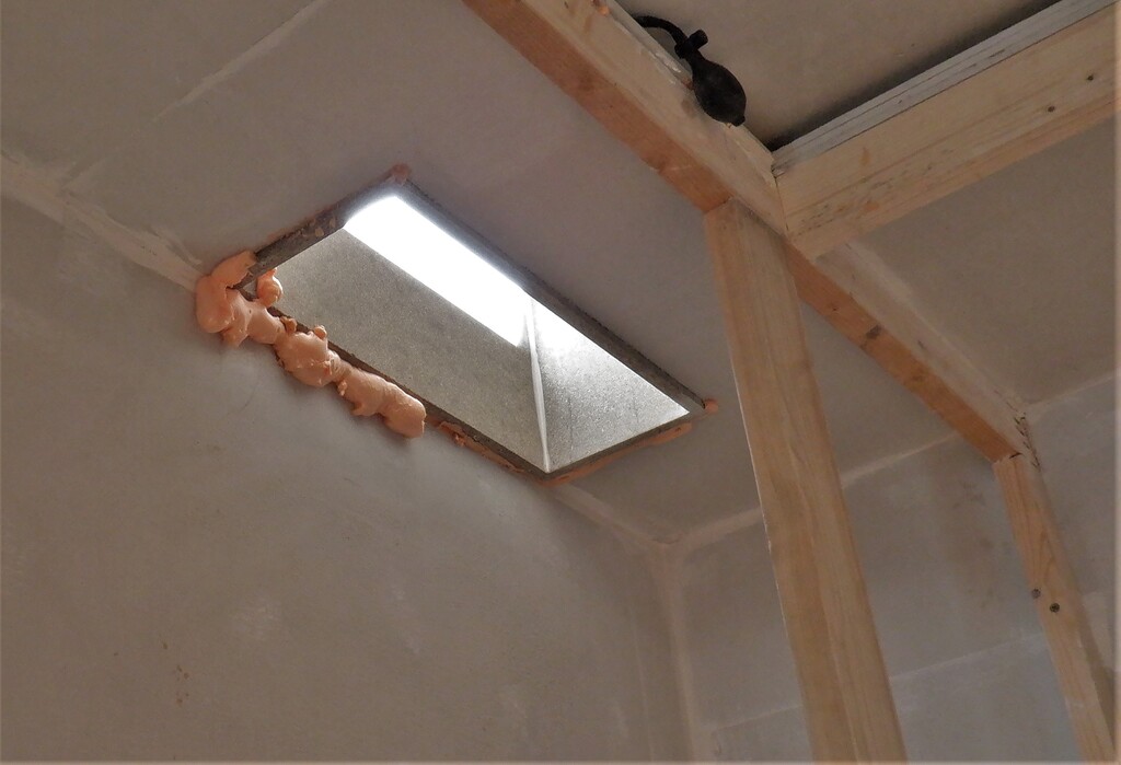
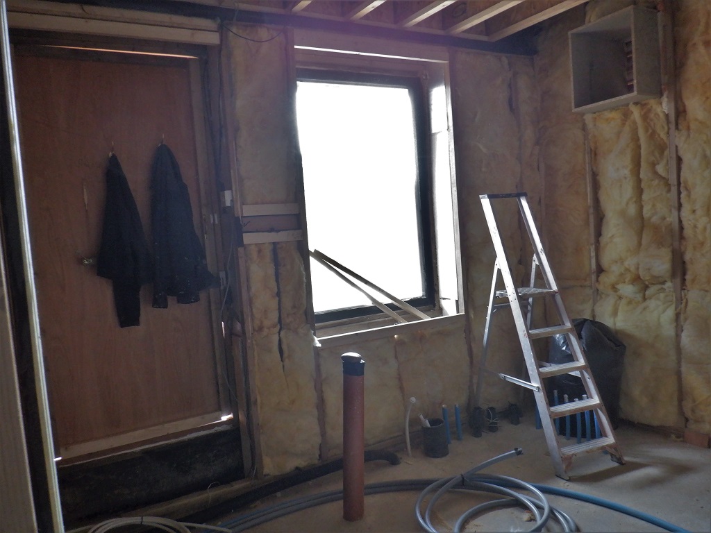
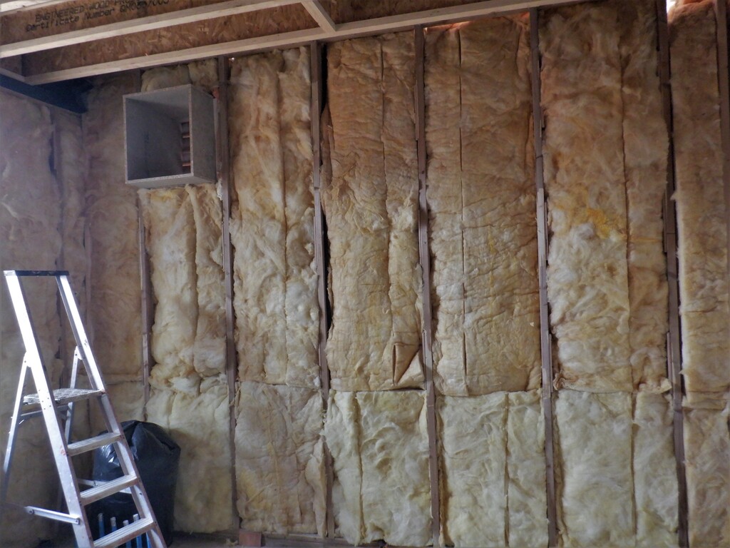
Today, we started the task of installing the air ducting for our fresh air. We decided to tackle this particular job now as we are waiting for more building supplies to come, plus also, we are waiting for warmer weather to stop the condensation from forming up in the Skylight. We need to dry out the moisture before we continue replacing the lining up in the Skylight.
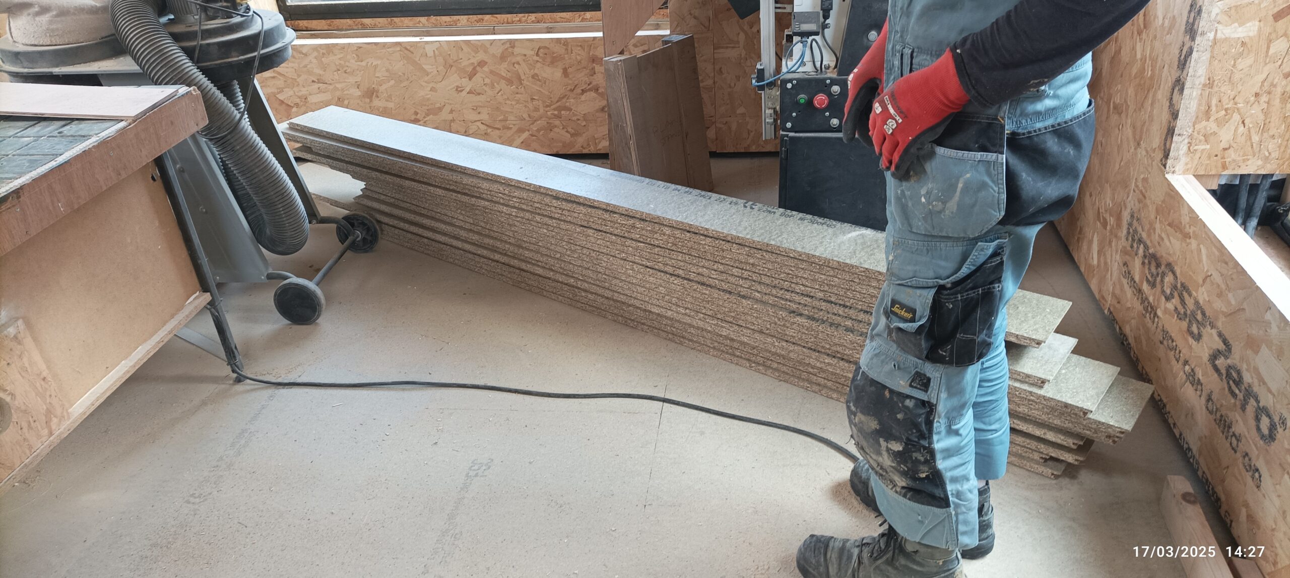
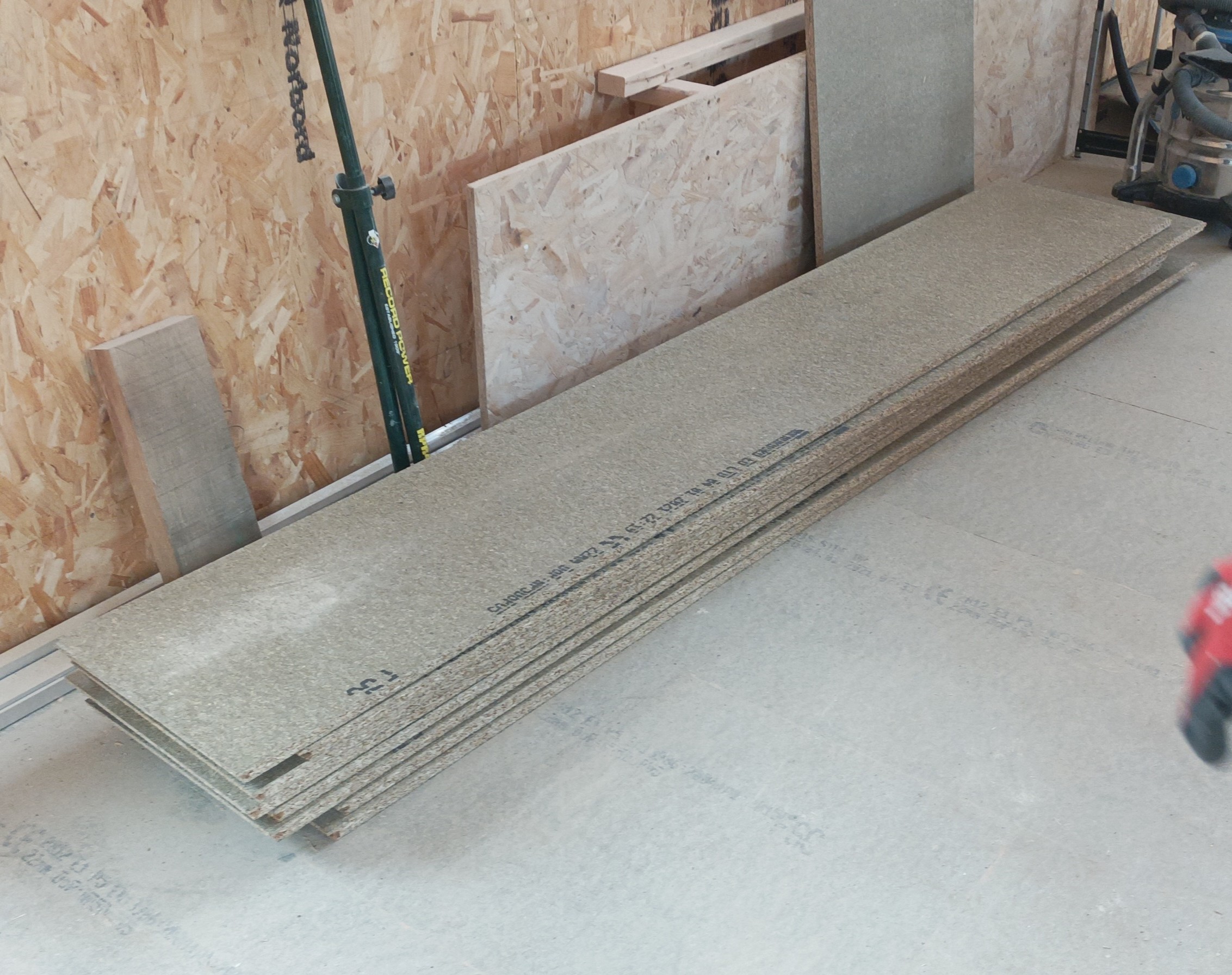
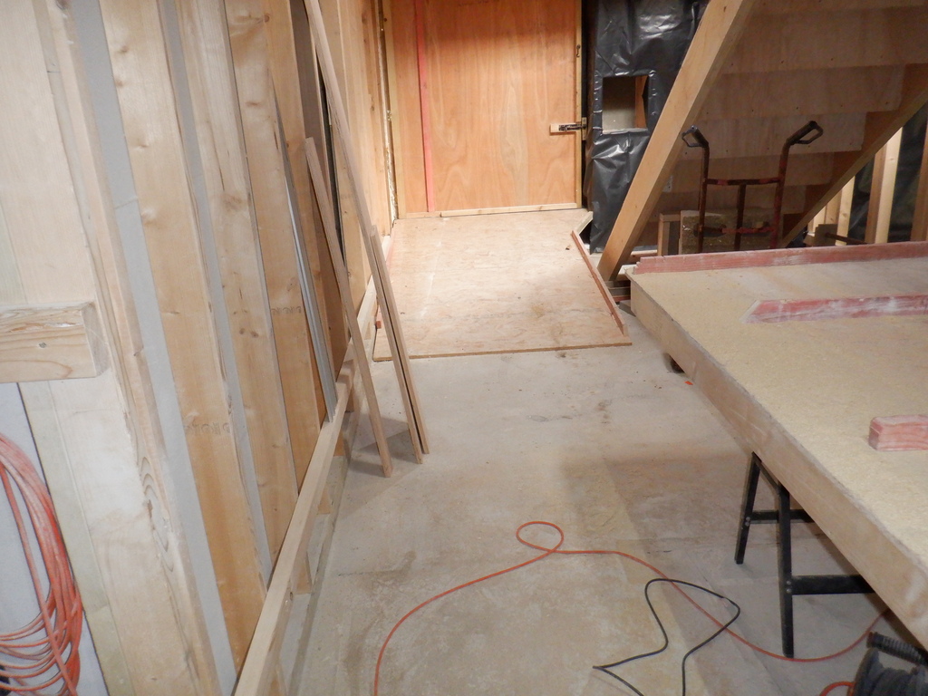
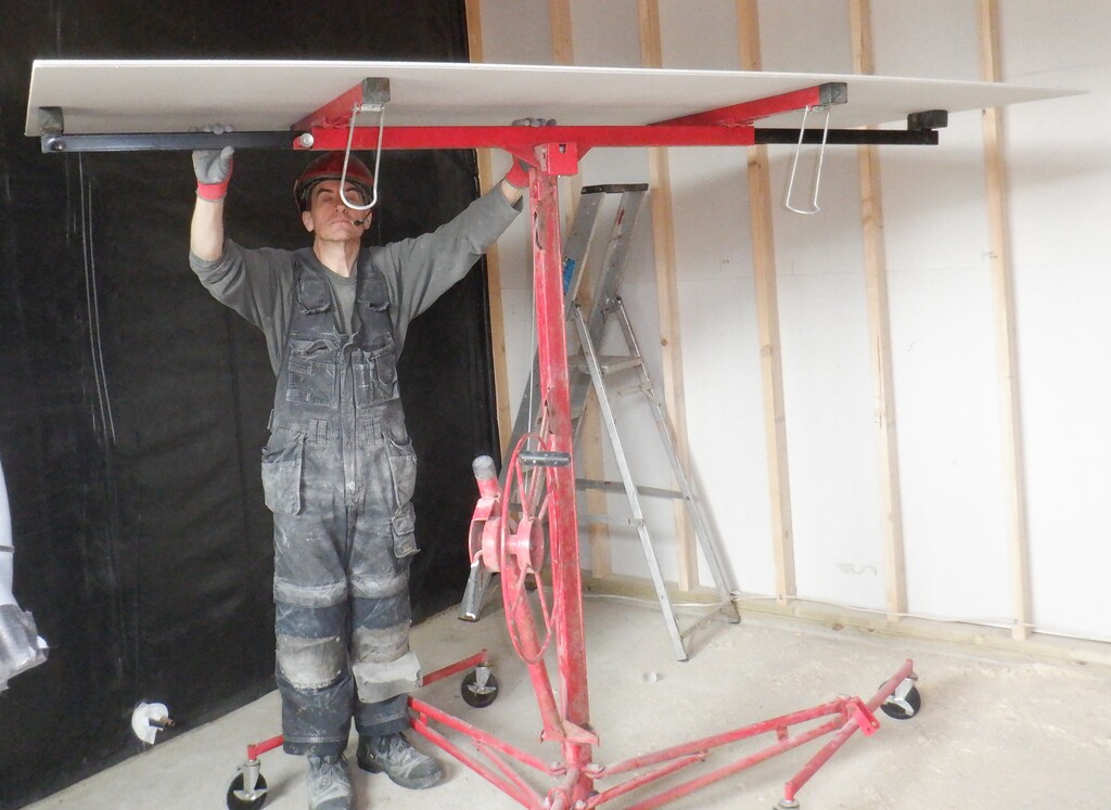
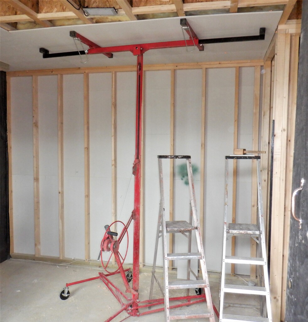
The Air Ducting is needed to be built, to take our fresh air from the Utility Room, down underneath the floor, across the room, into the hall and down long the hall, going all the way to the Great Room and the Conservatory. This distance is 22metres approximately. We got a pile of left-over chipboard boards, that already had a coat of varnish painted on them, to seal them against moisture. There are twelve sheets, measuring 580mm wide by 2400mm long. We needed to sliced these boards up in such a way that we had the section in Hall Three created with 150mm high sides as the framework for supporting the flooring was done in a different method., compared to the rest of the flooring. And, Hall Three is about 5metres long, which is two sheets. So, we sliced two boards up, making the 150mm wide strips and the left-over piece will then become the base board of the ducting. We needed two more 150mm sides so we passed another one of our twelves boards through the table saw twice more, so we ended up with four equal 150mm strips. Now, we adjusted the saw table to a new width of 178mm because the rest of the framework under the floorboards, has more room but slightly narrower. We can fit in a 400mm wide base board instead of the 430mm that is in along Hall Three and after taking off 400mm the original board width of 580mm, we were left with 180mm. but before we go for that size, we have to take into account the thickness of the saw blade itself, which is just over 2.1mm thick. This is why we have gone for 178mm. So we sliced seven more boards to produce a single strip of 178mm and a left-over piece of 400mm. Now, we are left with two boards and we proceeded to slice these up into six 178mm strips, three off each board. And finally, one of our left-over piece, we also passed through the saw table to produce that seventh strip, to go with the first set of seven, to make the two sides of the Ducting, for each of the seven base boards.

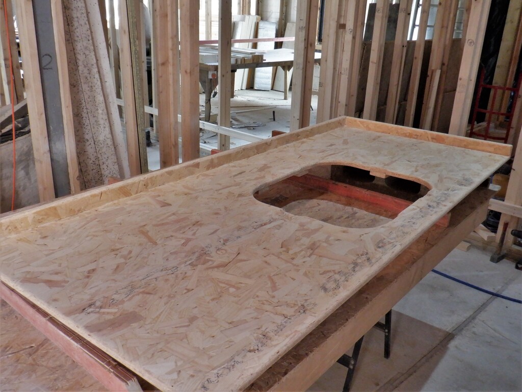
Sliced Up Boards

Sliced Boards 2
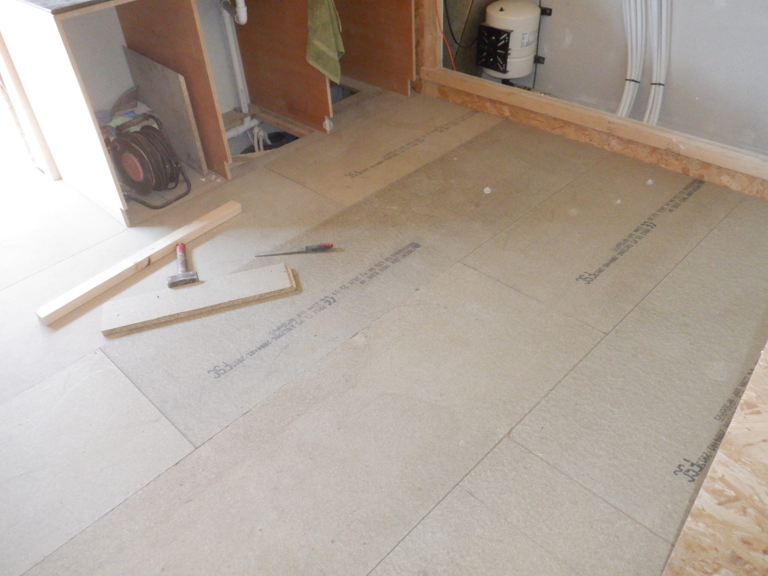
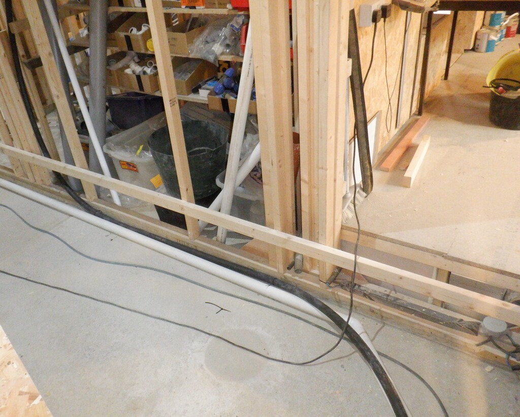
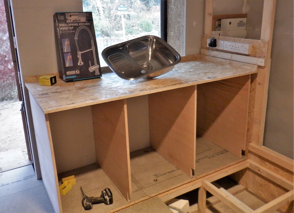
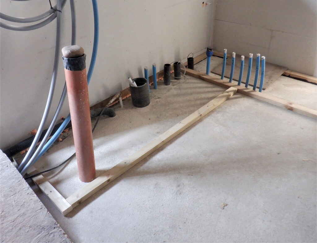
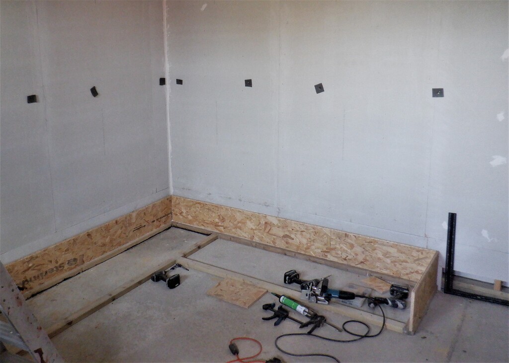
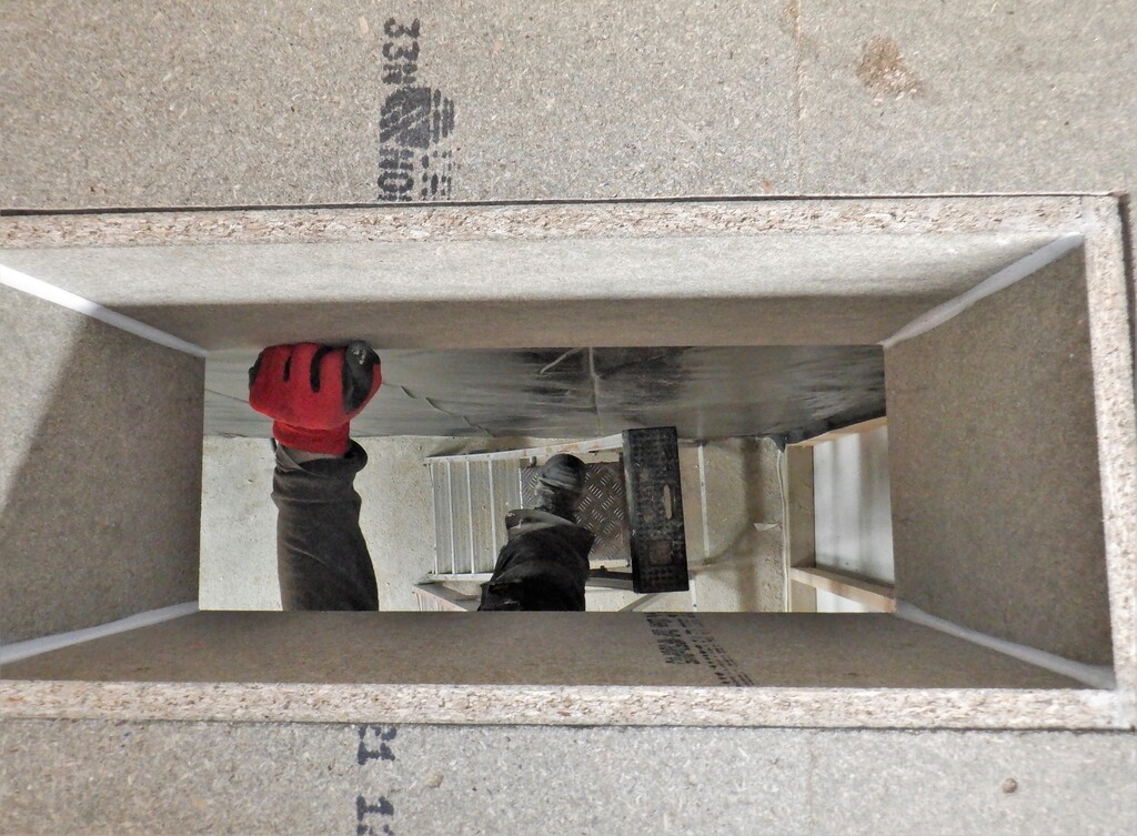
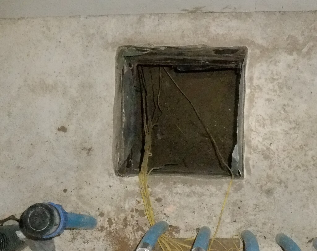
So, starting in the Utility Room, we lifted a strip of floorboards, the line next to the Utility Cupboard that will contain the tumble dryer cabinet, the vacuum machine and small cupboards. There is a couple of layers of 50mm thick PU foam boards sitting on top of the concrete so the Ducting can sit on top of them. It just so happens that the gap between the foam boards and the floor joist running around the edge of our Utility Cupboard, is 200mm high. This is ideal because our base boards are 22mm thick and our sides are 178mm high, and fancy that, that makes 200mm in total !! We proceeded to saw out an rectangle hole through the cupboard wall, which is made up of two layers of 18mm OSB and one layer of 10mm Fermacell plasterboard. We sliced a 400mm wide by 200mm high hole, and our base board now can slide all the way along and into the Cupboard.

Across utility
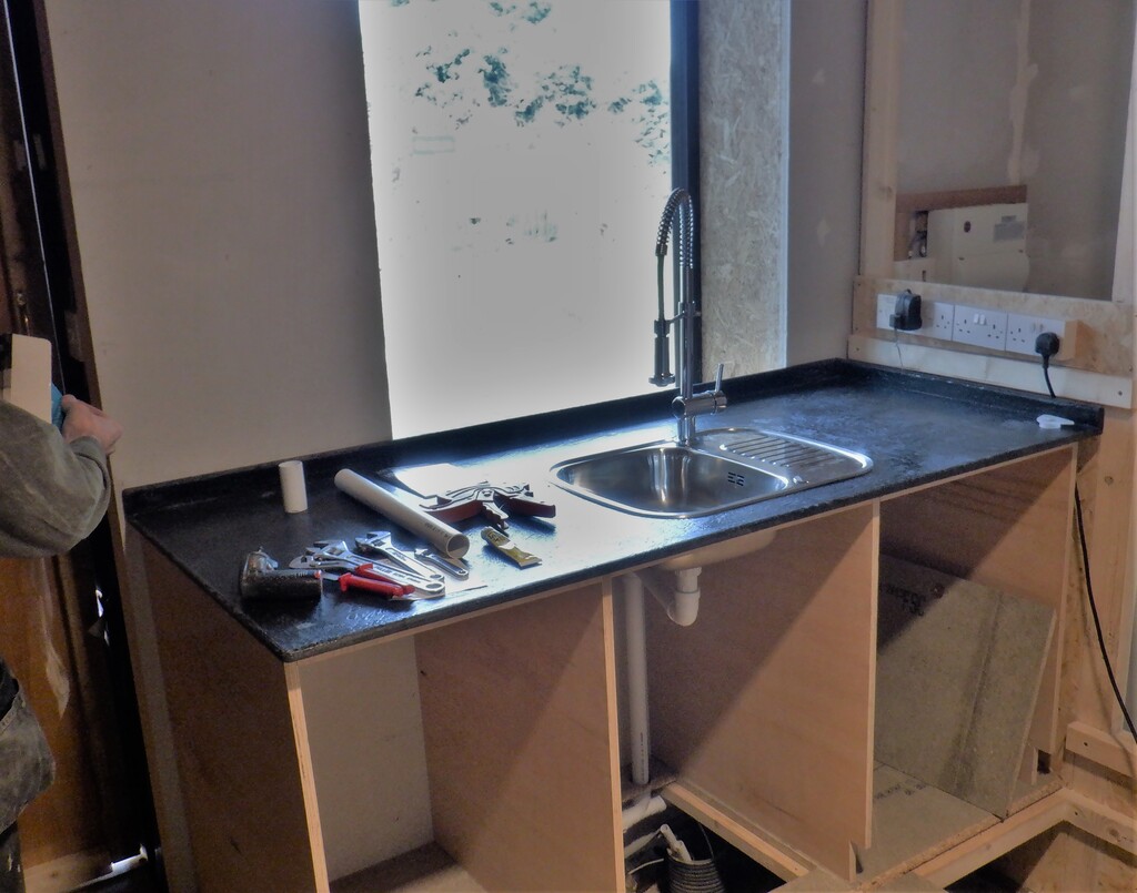
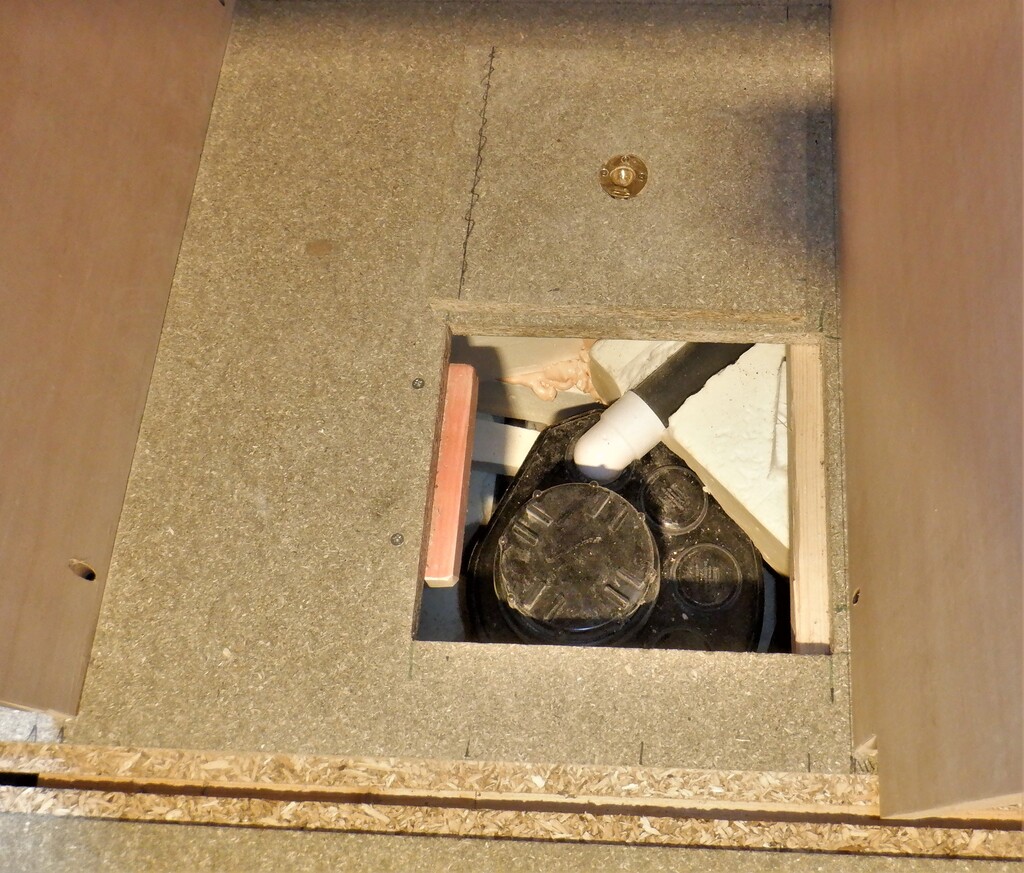
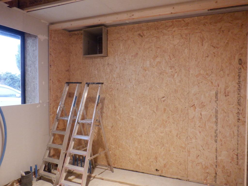
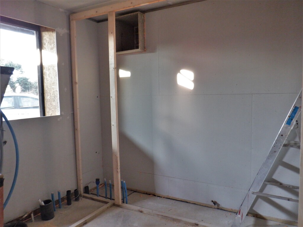
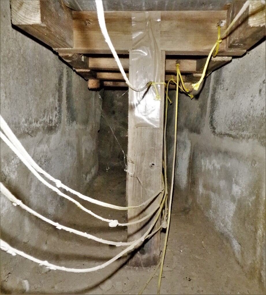
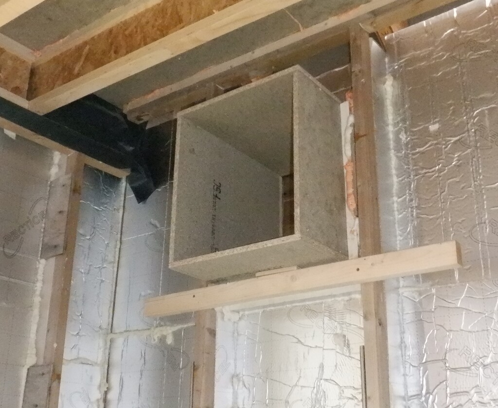
Next, we built a side-shoot off to the side cupboard that houses the tumble dryer cabinet and the vacuum cleaner system so that they can have fresh air, plus also the Study Room upstairs needs a connection to our fresh air supply as well. Oh yes, the Utility Room itself also needs a heated fresh air supply as well, plus also, the vacuum system will need a supply of cooler air, to keep the motor from overheating. We realised that this side branch cannot have any control valves or flaps because it will be underneath the floorboard and they will be glued and screwed down (eventually!), which means, we cannot service the mechanisms etc. Hence why we are having a fairly large opening in the main duct and having it angled into the side branch. We used a larger piece of our coated OSB board to make this junction.

Side branch in utility
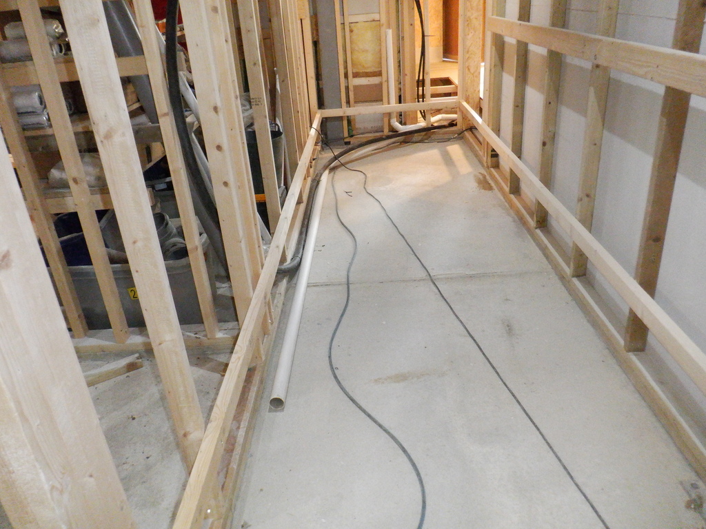
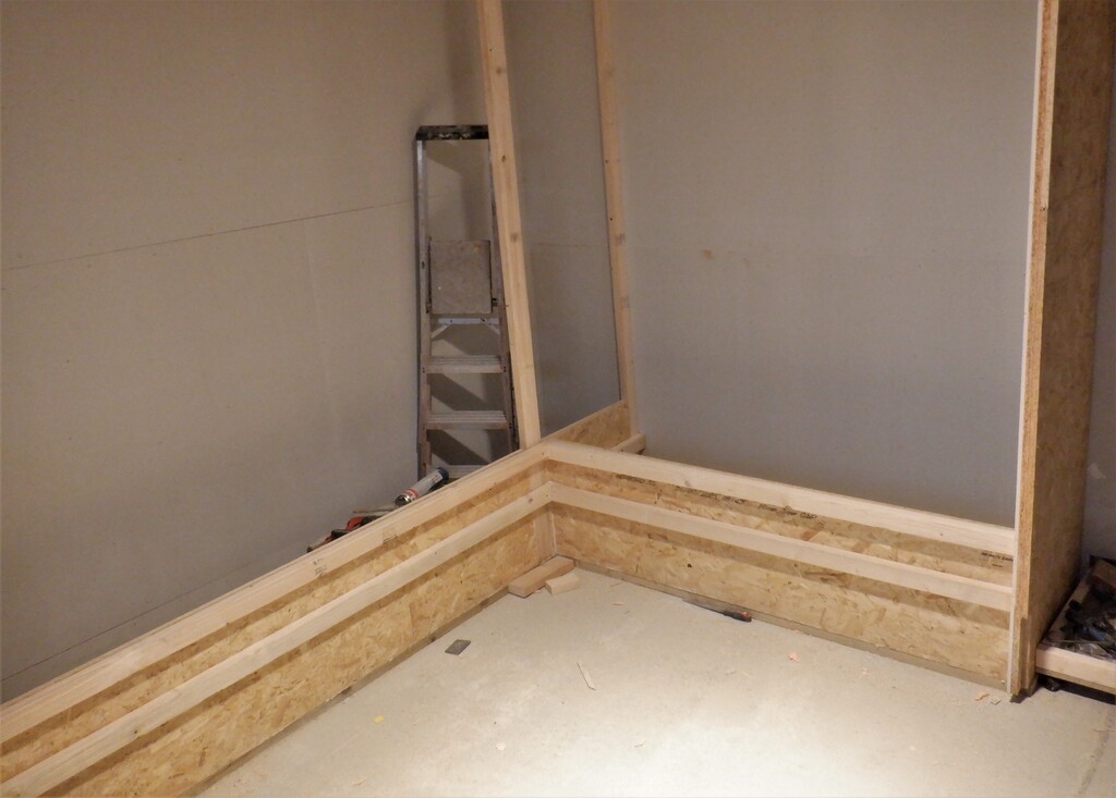
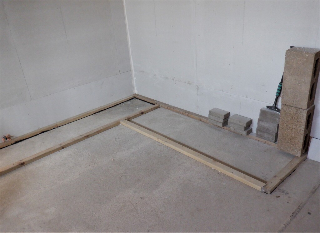
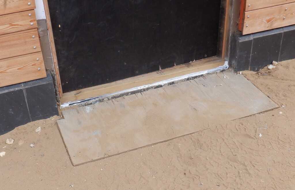
We then carried on with the 400mm wide base board, turning the corner at an approximate 45degree angle and headed out underneath the doorway into the Hall, to connect diagonally to the next straight section running down Hall Three.
Now, we took our vertical side pieces, the first ones being 178mm tall, to go from the Utility Cupboard towards the doorway. But, we realised that they were too high to allow us to slide a 6mm lid into place. So, off we go back to the saw table and slice off another 8mm, to give us room to get them in.
For our side branch, we cut the compound angle on both pieces, half 45degrees, so that the joint was nice and neat. When it came to the side pieces for going under the doorway, it is a change of hight again, because the main ducting in the Hall is slightly higher up and slightly wider, being 150mm high and 430mm wide. So, that meant that the sides needed to be trimmed so that it fitted the gentle slope up, including to remember the extra 8mm gap to get our lid in. It was tight, very tight but we managed it.
Now, we had to put in lots of pocket screws into the side walls, to help screw the pieces tight down to the base board, plus a load of glue as well.

Turn into the hall
Once the glue had dried, we went around shaping the corners so that the air can flow more smoothly around the bends, especially the outside corner where we put in a thin sheet of plastic that can gently guide the air around the bend. We then taped up all the joints, corners and so on, with aluminium metal foil tape, to make sure that the joints are air tight and also provide a smoother path for the air too.
Next, the lids were made of just 6mm MDF boards. We Got a full sheet off our rack and coated one side with two layers of varnish, to seal it in against water moisture.
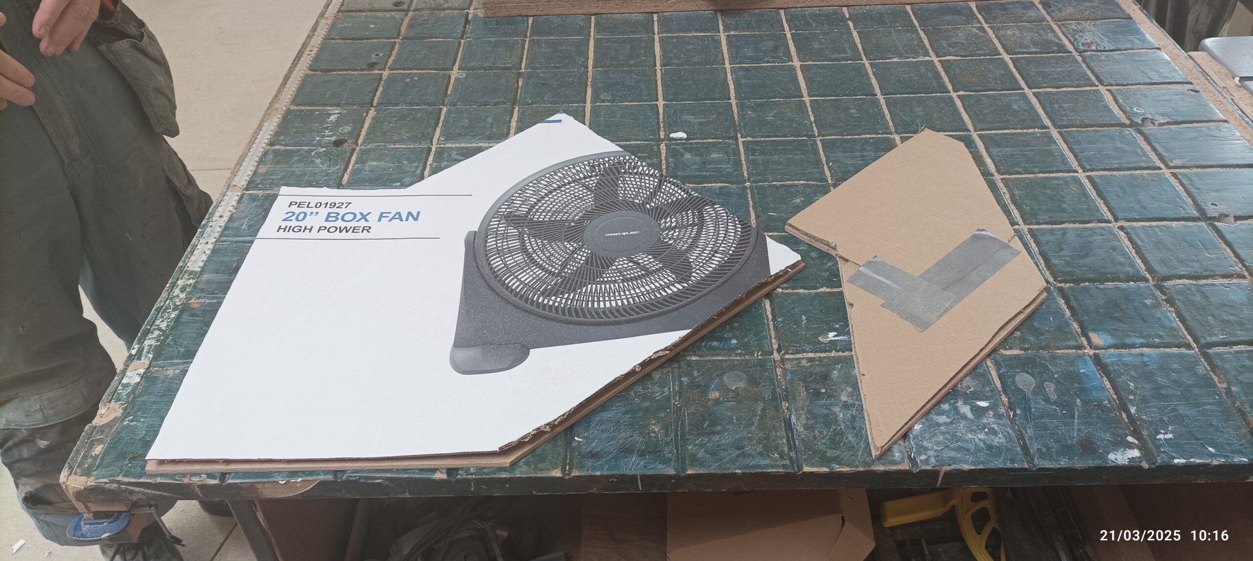
We then sliced three strips off the narrow direction, creating 400mm wide pieces by 1200mm long. We proceeded to to slide each one into place over the air duct, cutting the necessary angles, to make them fit and going around the corner. We used a piece of carboard to “map” out the shape of the lid and then transferred it over to the MDF sheet, to cut the finished article. We did both the side branch going into the side cupboard, and also the bend towards the hallway using this method.

Corner Template
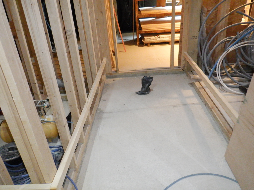
Next, we screwed the lids down and then taped up the joints with more aluminium tape, to seal against any leaks.

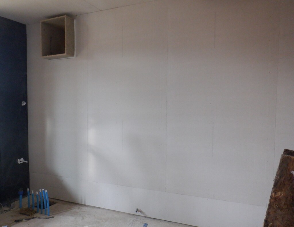
Covers on in Utility
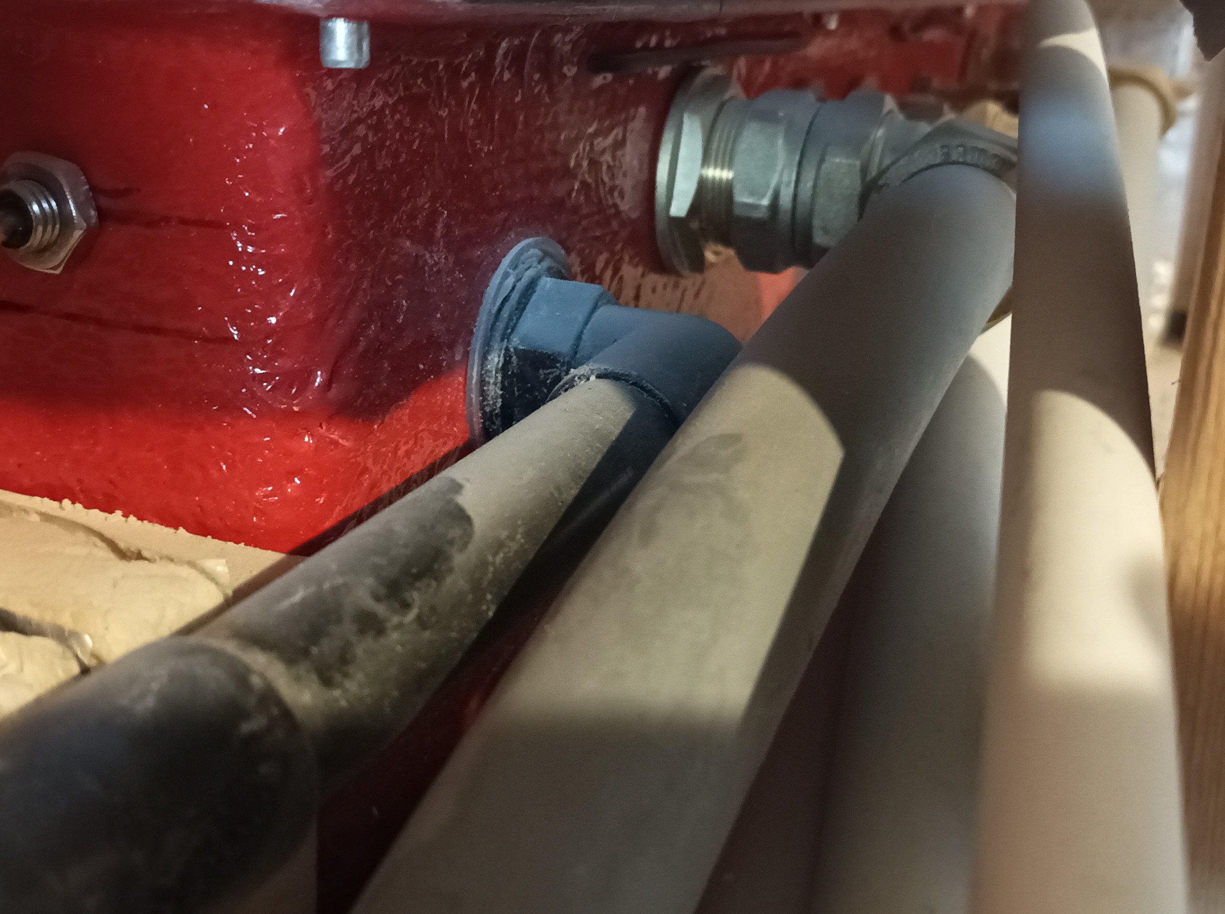
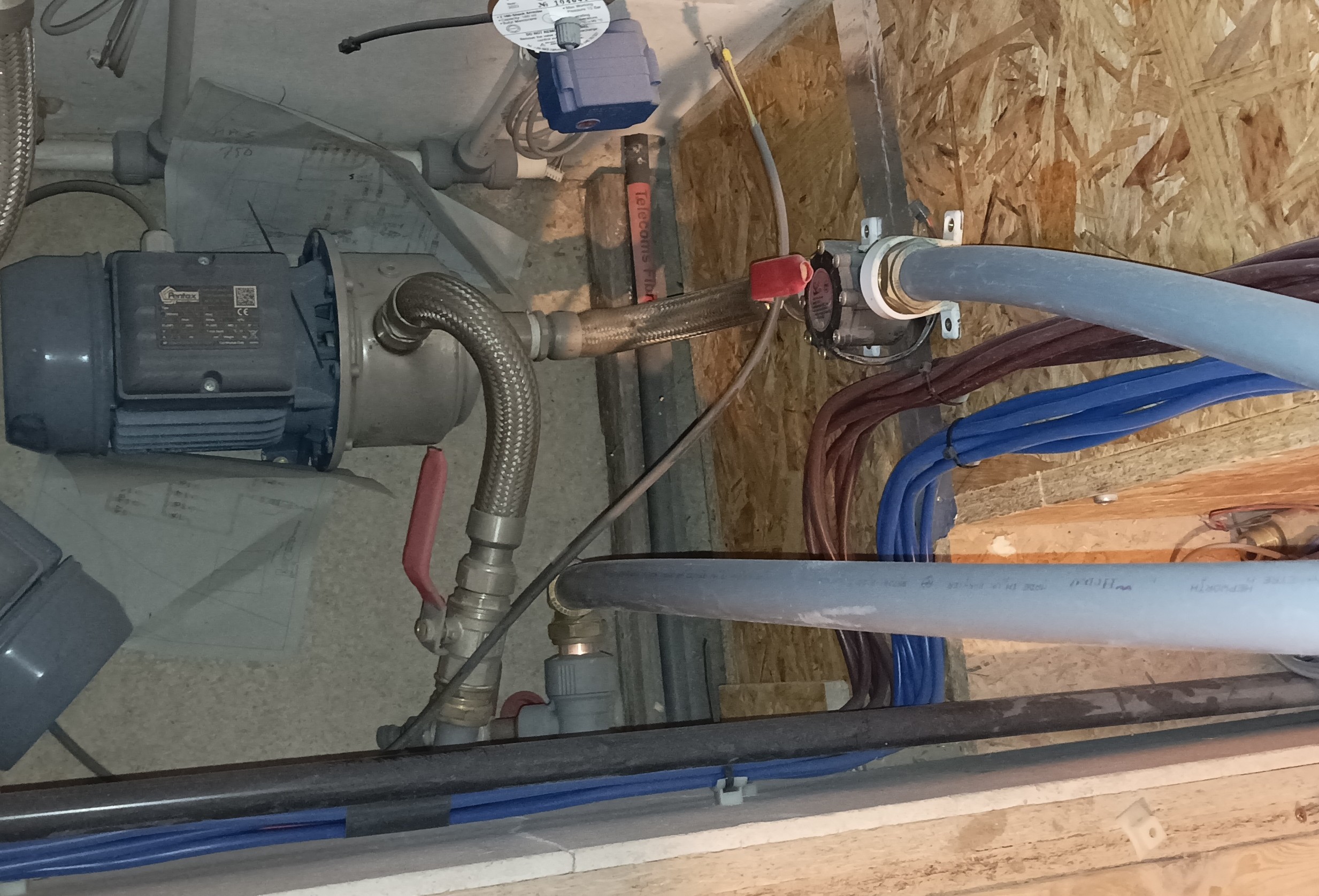
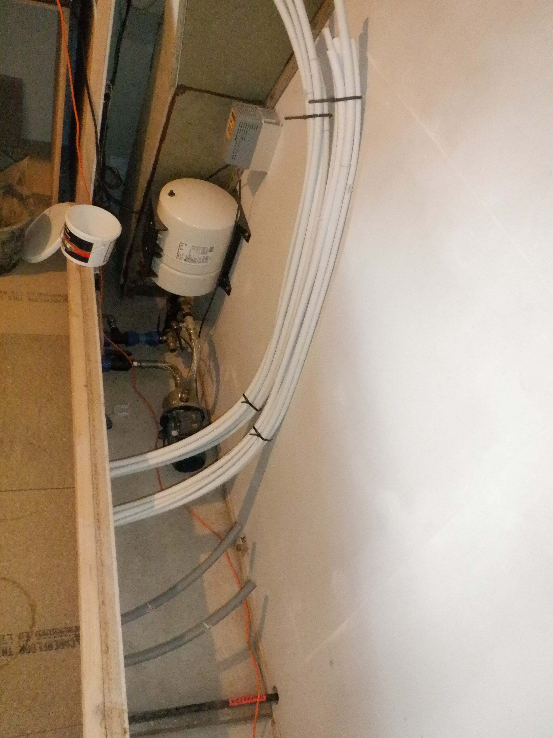
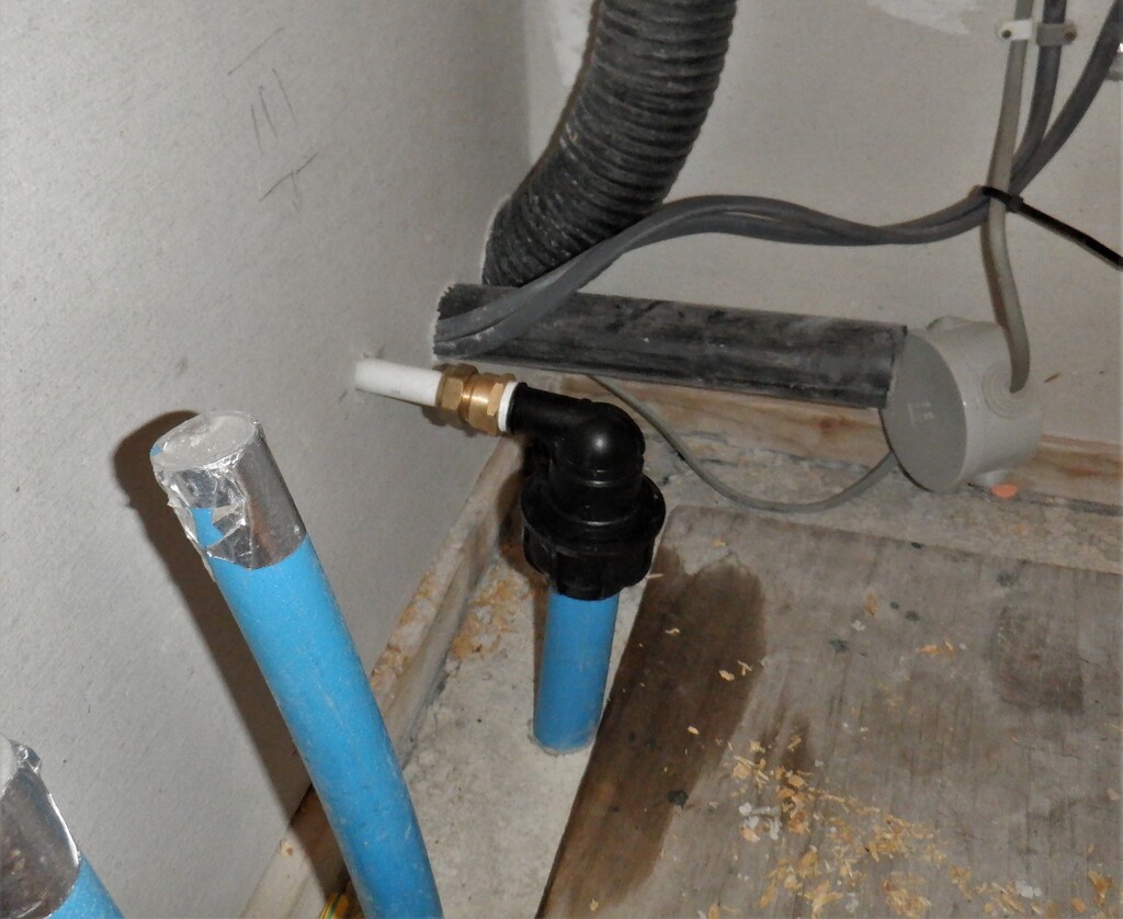
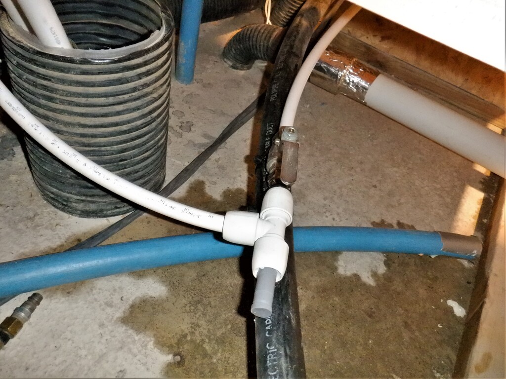
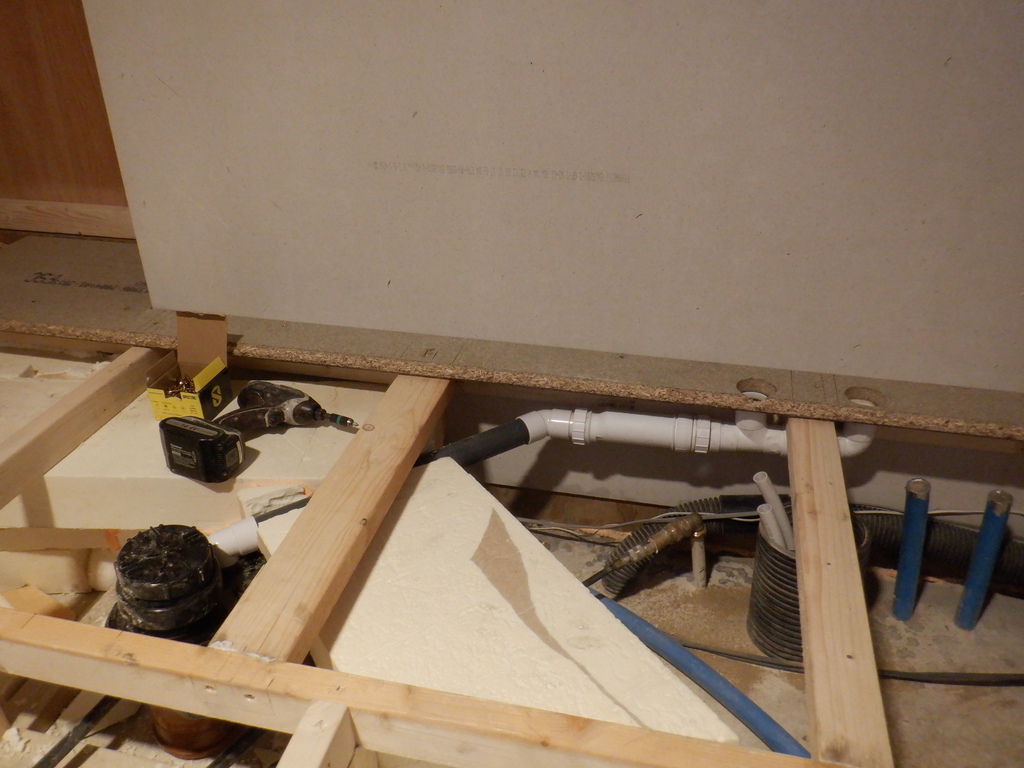
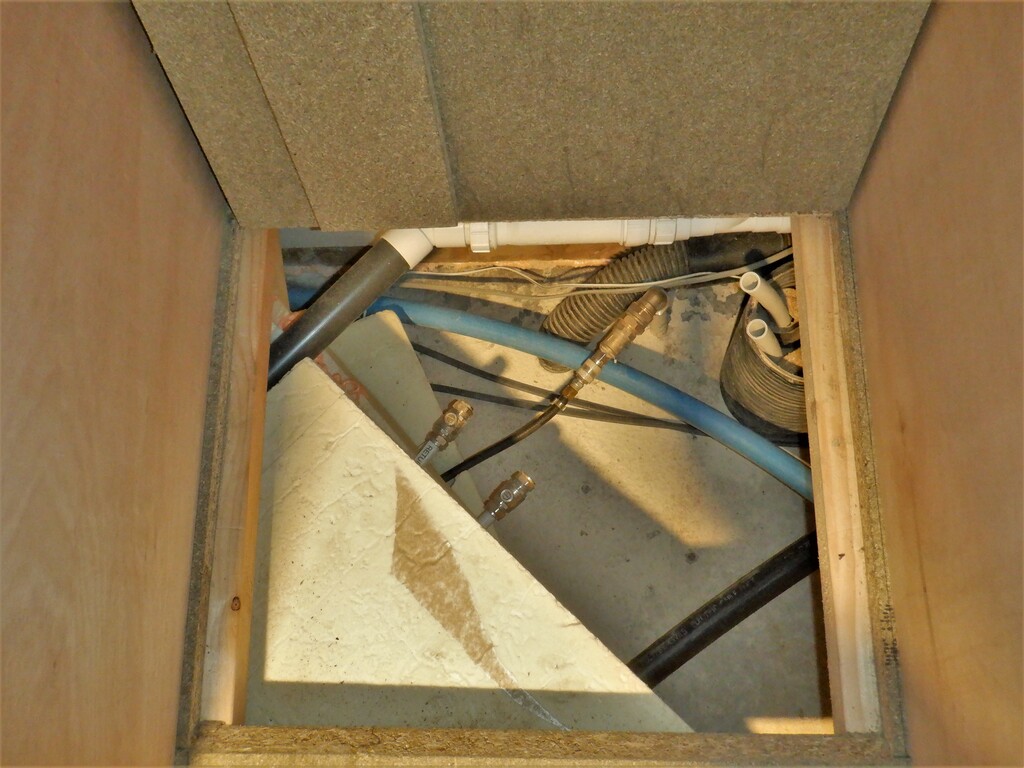
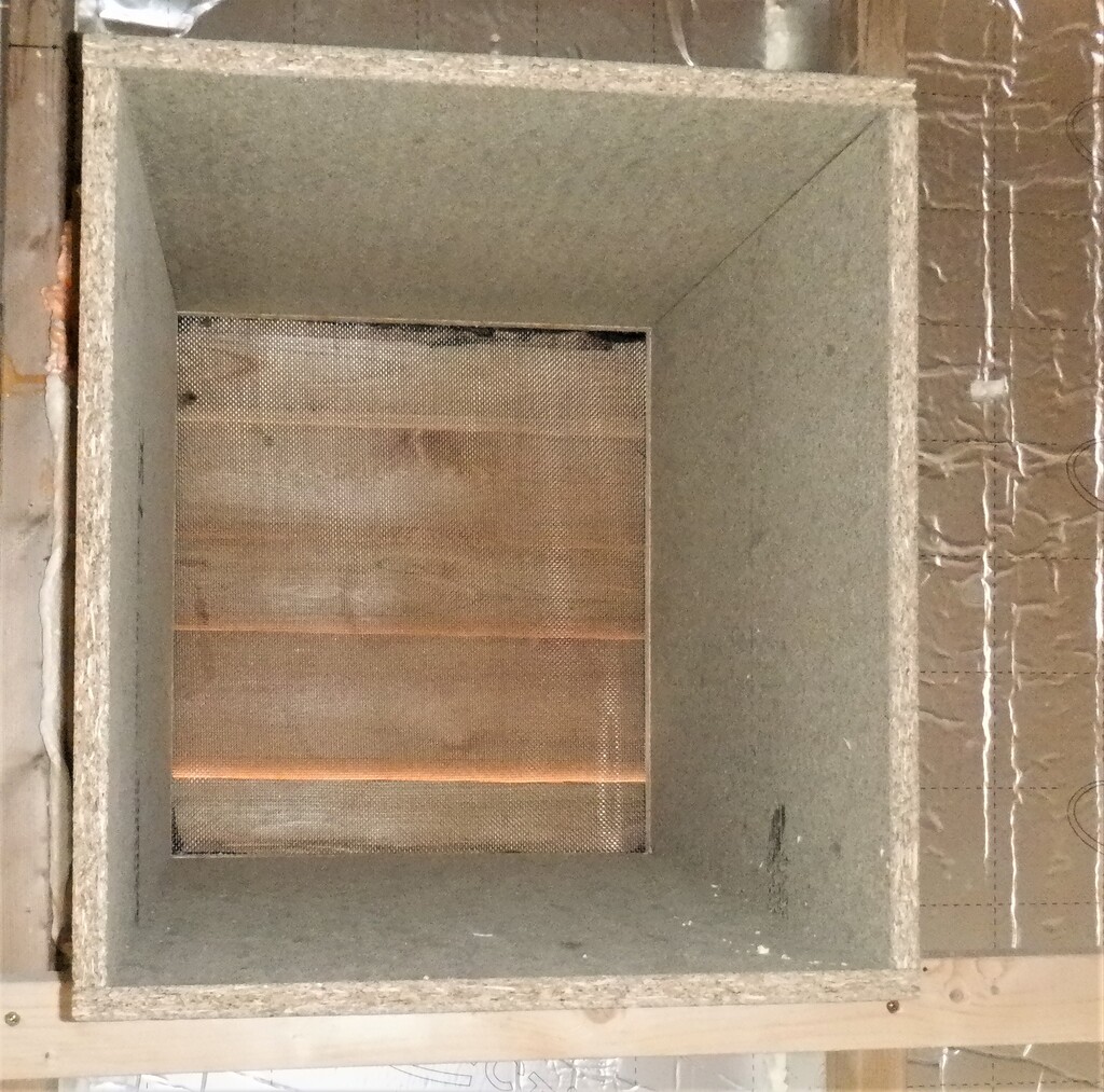
Finally, before laying the floorboards back down again, we drilled two 70mm holes into the wall of the side cupboard, and inserted two lines of our 50mm flexible conduit. This is going to be the hot fresh air supply for the coat hanging and footwear rack section, over beside the main exterior door.

50mm Ducts in Utility
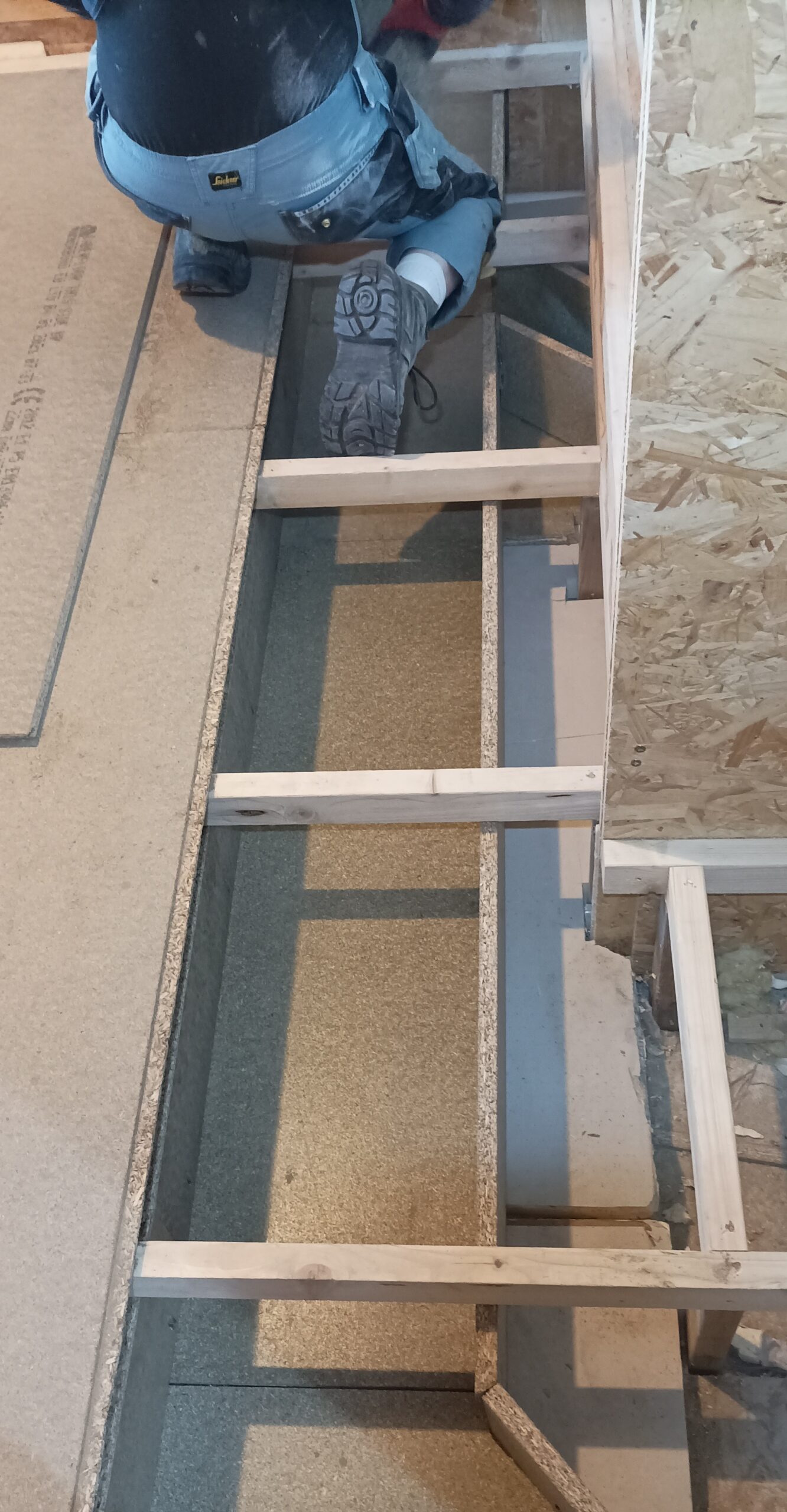
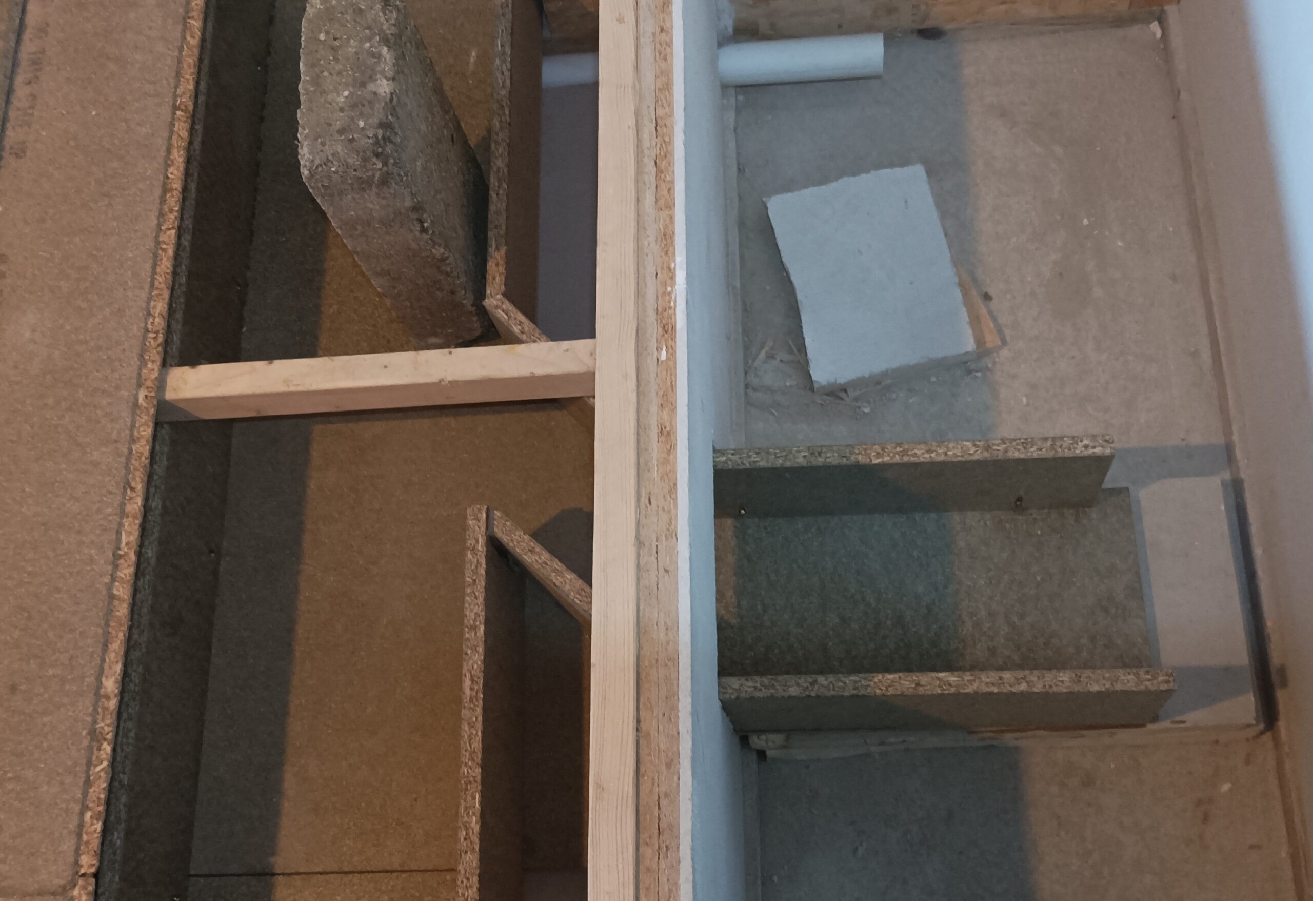
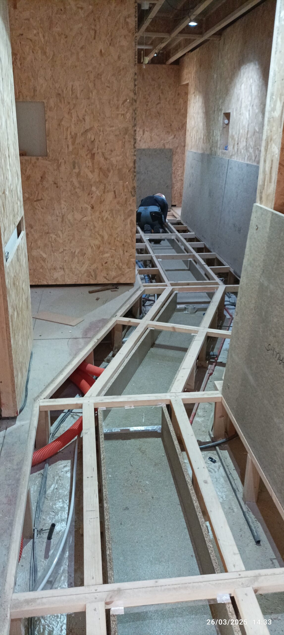
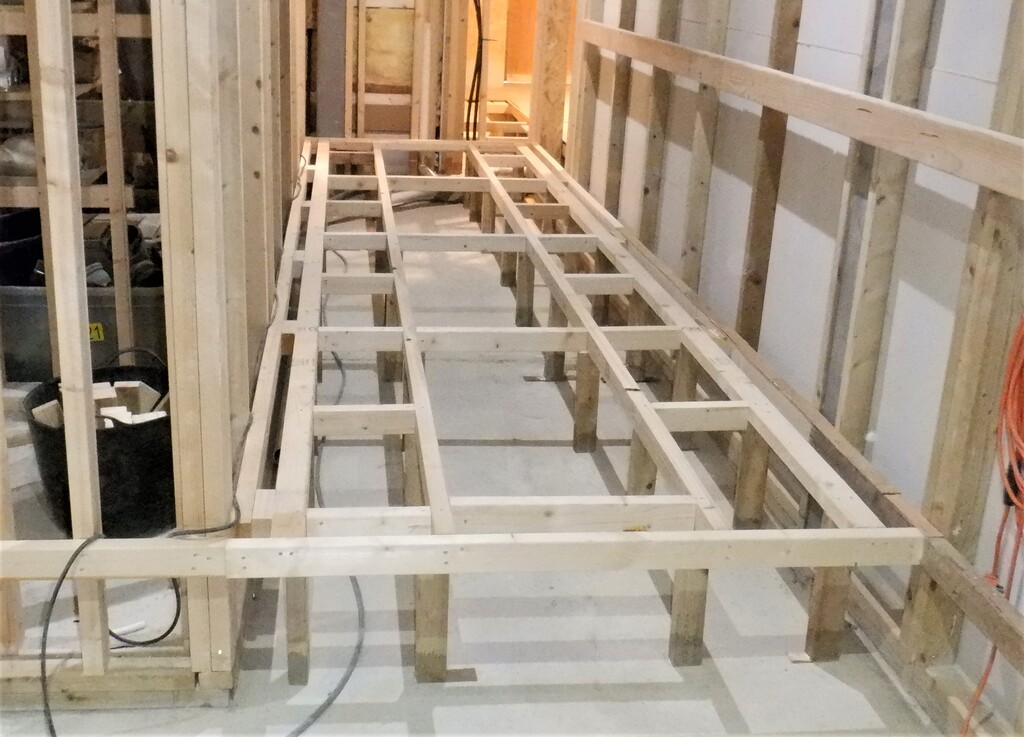
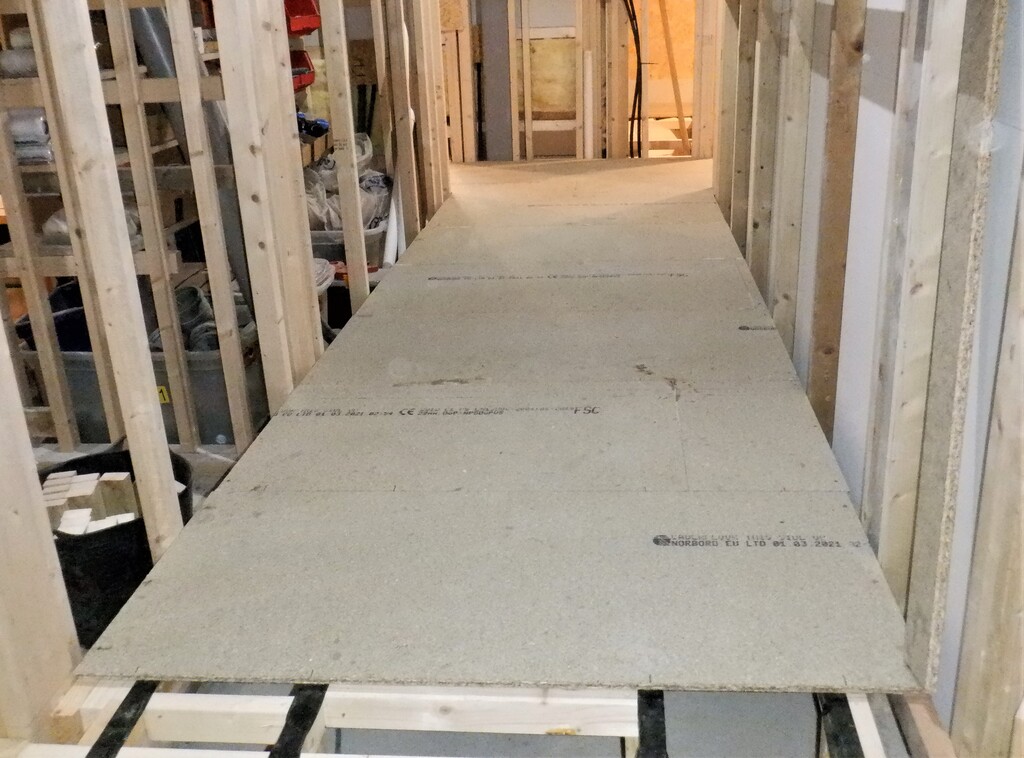
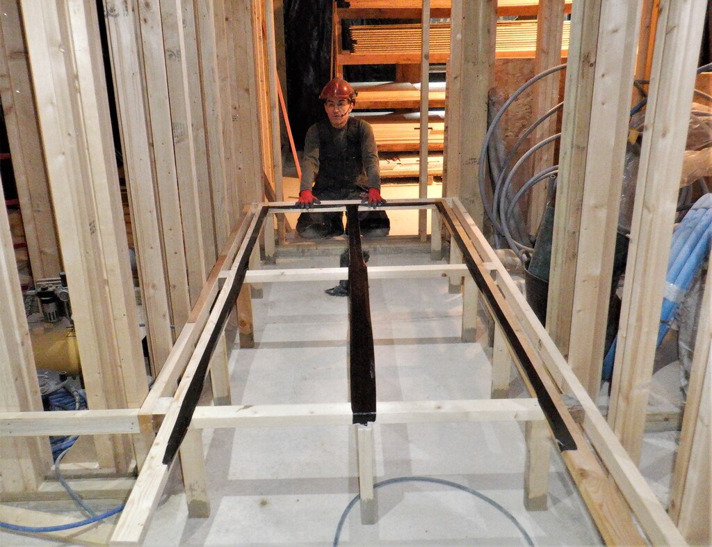
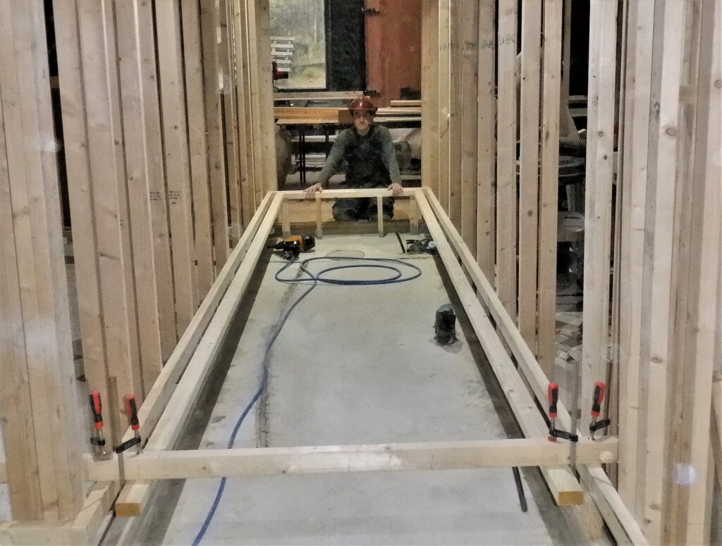
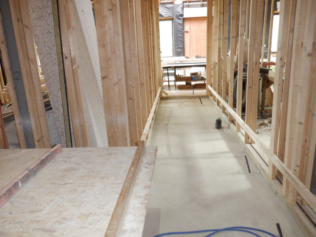
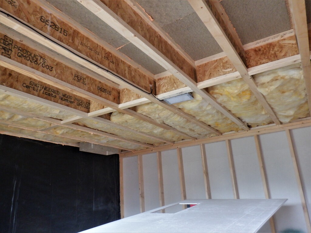
Now, we carried on down Hall Three, this time, laying down 430mm wide base boards and 150mm high sides. We made little wooden wedges so that we could jack up the air duct so that it is tight underneath the cross rails that are the framework holding up the floorboards. We then crossed diagonally slightly at the Cross road Centre, which we changed over to 400mm wide and 175mm sides. The base board actually stays the same level, it is the lids that goes upwards because the framework design for the floorboards changes to have 63mm CLS planks going flat across, instead of the more traditionally upright aspect. That gives us more room for the air duct to be taller by another 25mm, and we could reduce the width down a bit as well.
Anyway, we joined the Crossroad ducting in, having to cut the ends at an angle and then resumed the straight run down Hall One towards the Great Room. We again, had to cut a slight angle for joining to the base board in the Great Room. By this time, we were running very low on material as we had originally been using the pile of left-over chipboard floorboard pieces from building the First Floor and all the Ground floor rooms too. But, we just had enough for us to get three quarters the way across the Great Room. This is fine because the final destination for this ducting, is to supply fresh air to the Conservatory and we are planning to have an adaptor converting the output to four or five individual 50mm conduits, or perhaps 68mm rigid plastic pipework that we got loads of as well and taking fresh air to various locations around inside the Conservatory.
Everything was glued into place and one or two occasional pocket screws as well, to help hold things together while the glue dried. The doorway into the Great Room was a little bit more complex because the joists running across the doorway had 63mm CLS in their upright orientation so we had to fill in the gaps upwards and then cover it up with lots of aluminium tapes to provide a smooth transition from one side to the other side.

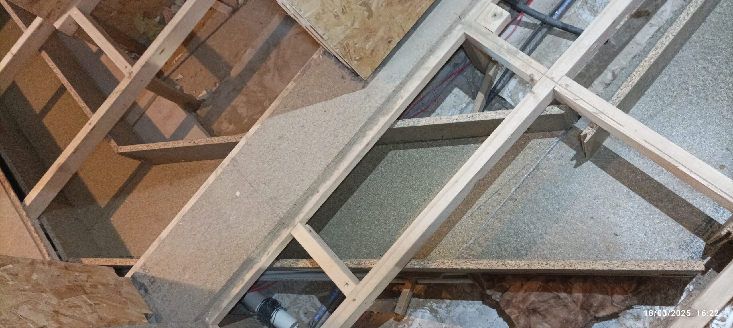
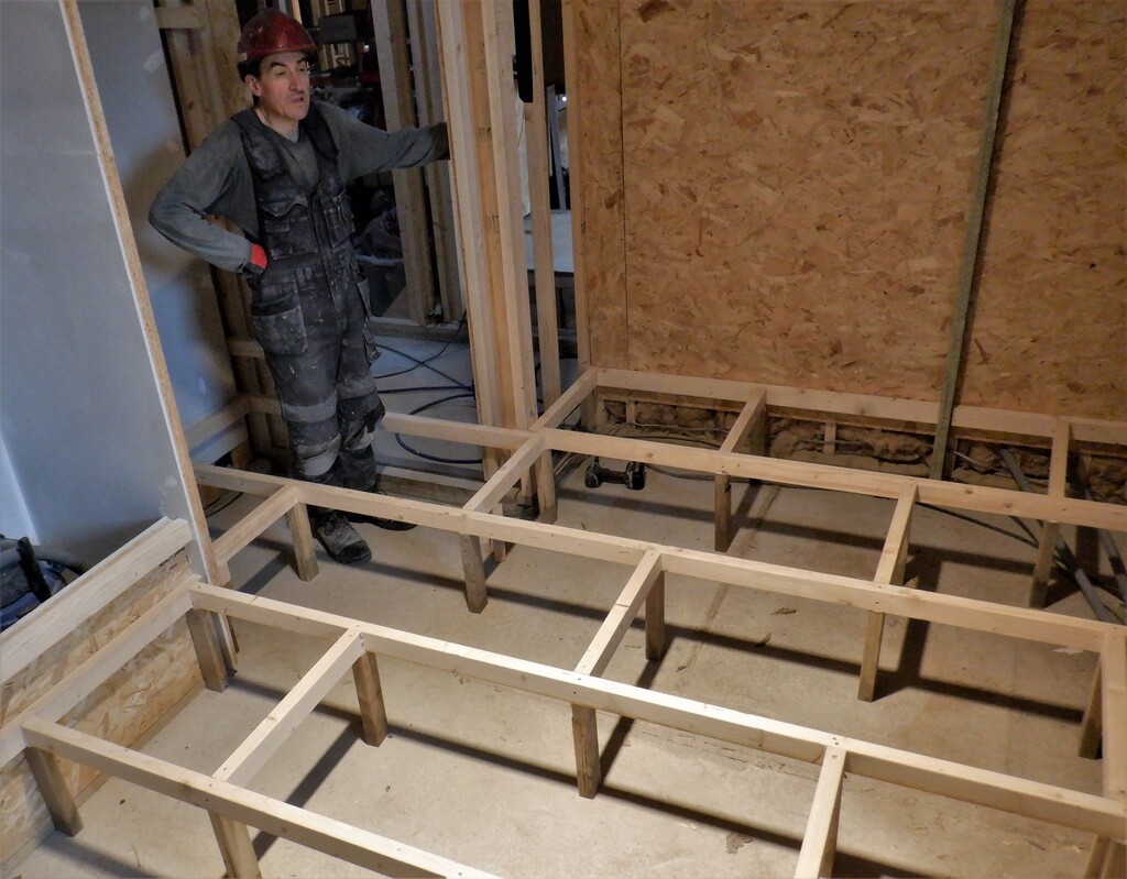
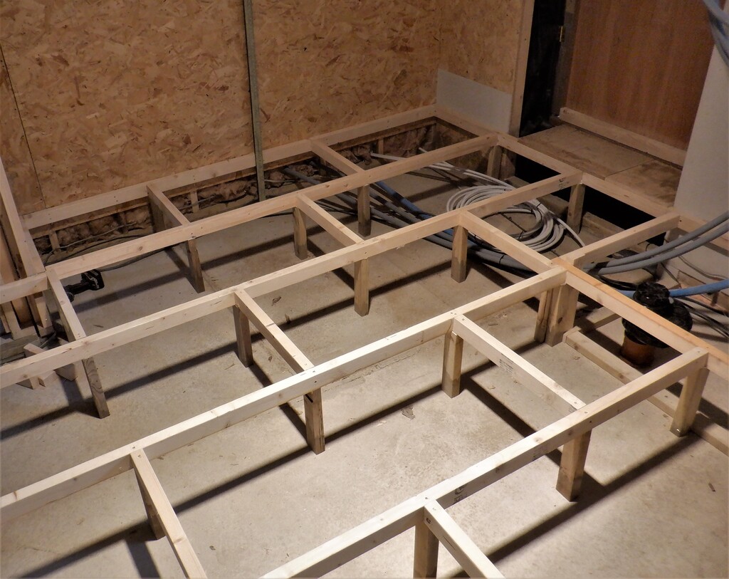
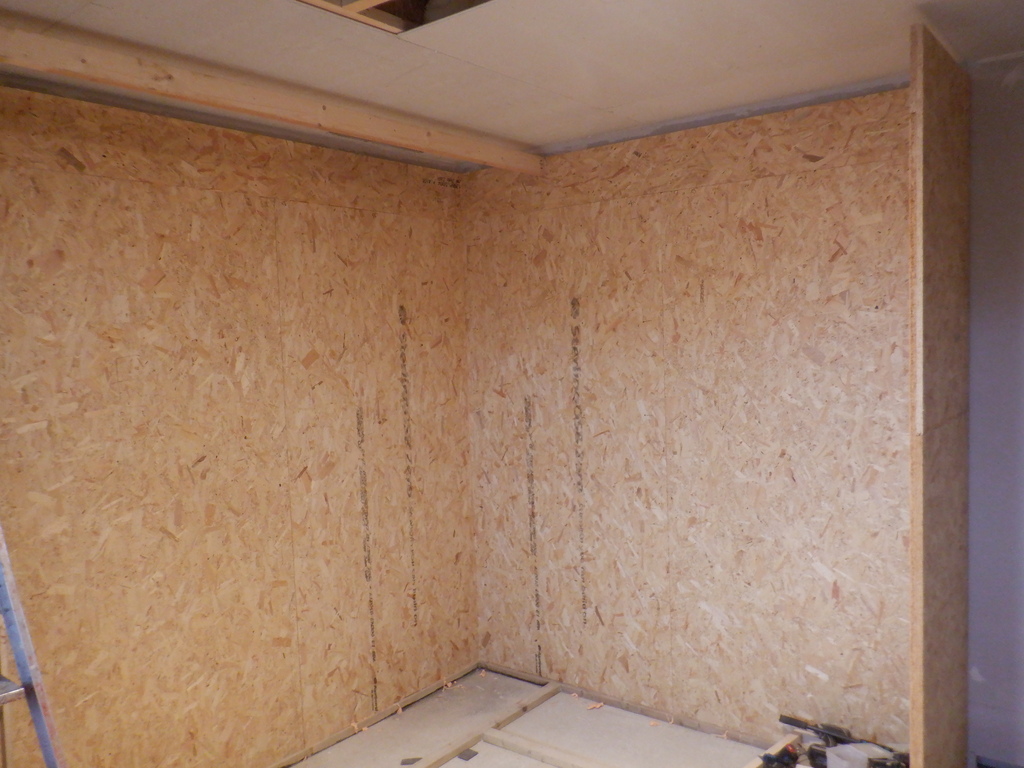
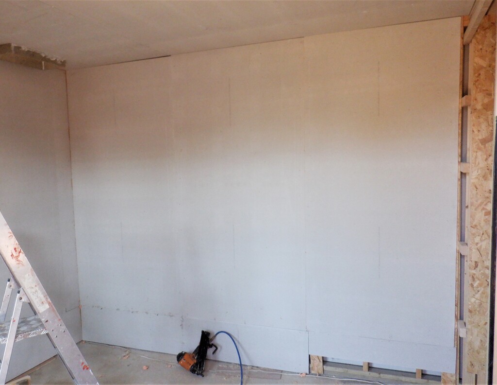
Hall Ducts built (1)

Hall Ducts built (2)
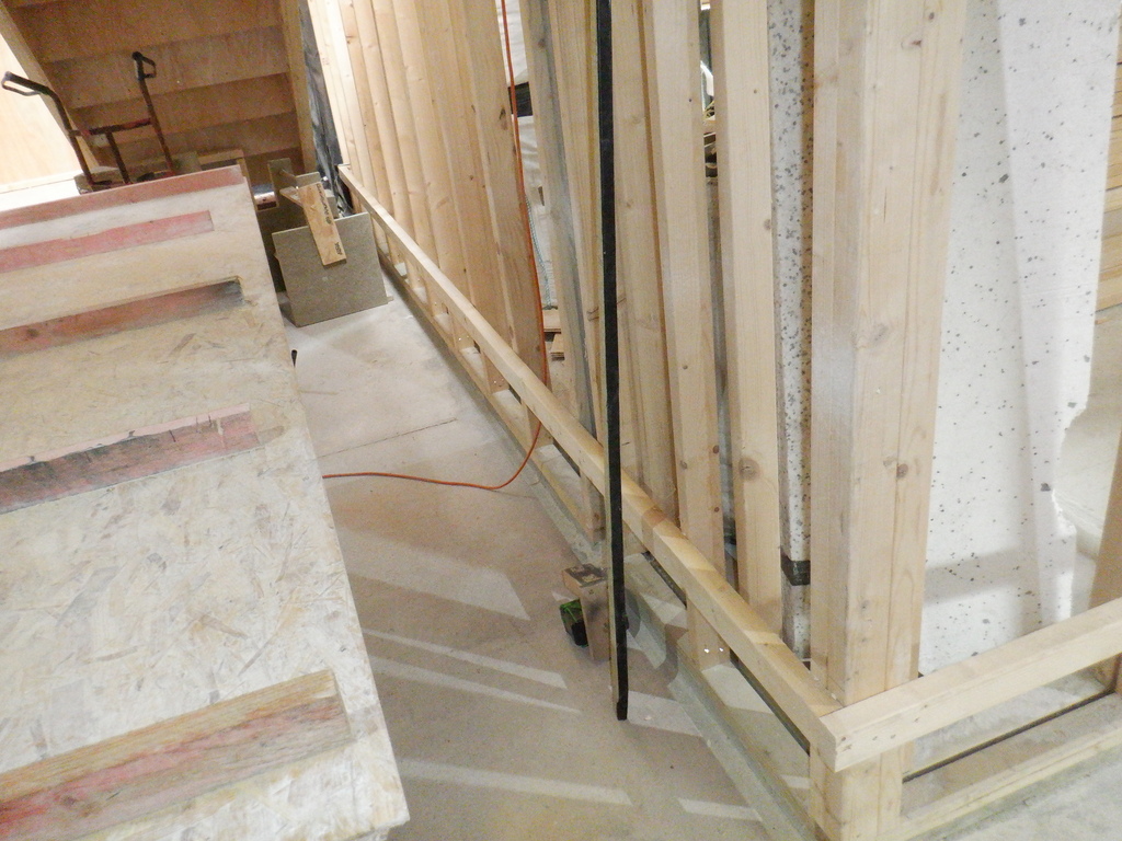
To add to this scheme of providing a smooth transition from one side, or chamber, to the next chamber, we made lots of small rectangular plastic strips to go underneath the cross rail, inside the ducting. We glued and stapled these clear thin strips and this helps to block off any air gaps that our lids may have generate. So we wanted to reduce any leaks as much as possible.
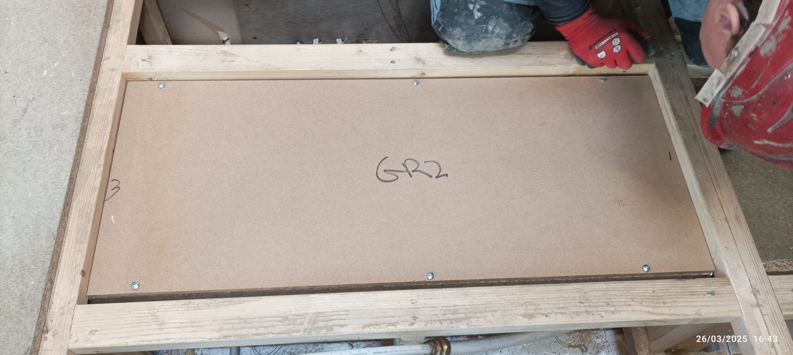
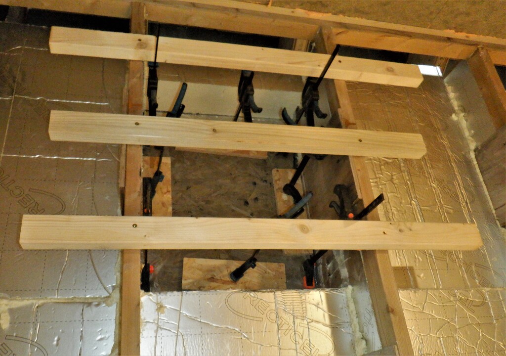
The next job is to make the lids. We estimated that we needed two-and-a-half sheets of our 12mm thick MDF boards. We proceeded to apply a nice thick coat of varnish on all three of them and allowed that to dry overnight. Next, we sliced 5 pieces of 400mm, well actually, 398mm wide pieces on our table saw!! We did five pieces off each sheet and the sixth left-over one was exactly 430mm, which is exactly what we wanted. We repeated this on the second sheet and then slice two more 430mm wide pieces off our third sheet.
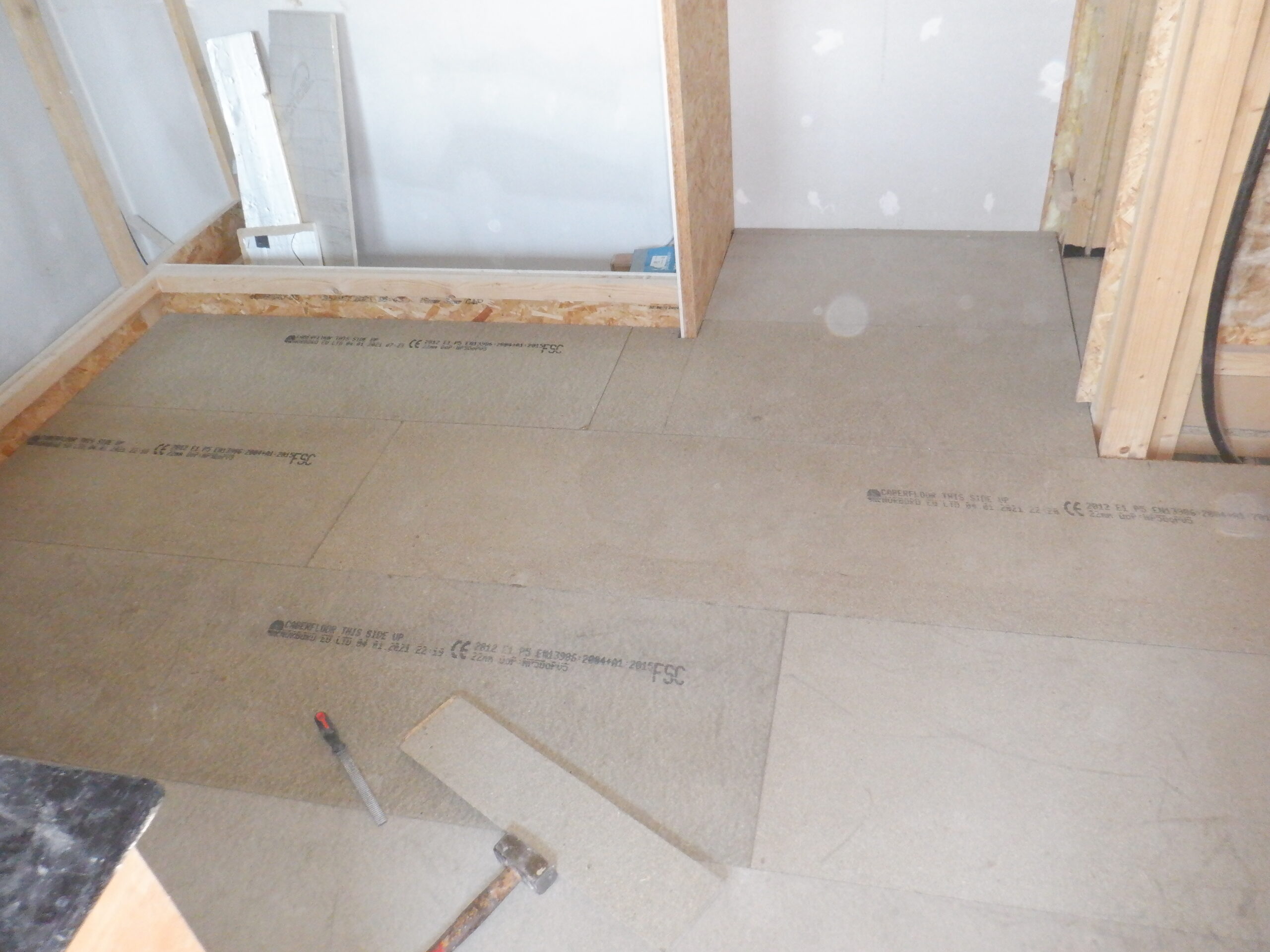
Then, we cut each one to exactly fit each section. We started in the Great Room and worked our way all the way to the Utility Room. We drilled 6mm holes down both long sides of each lids, three of them and then screwed in a captive nut into the side wall of the ducting. Each lid now has six bolts holding it down.

Lids all fixed down
That concludes the main 25metres of air duct, to deliver the fresh air to all our rooms!