Category: Phase 4

Construction of External Skin of House: External Walls, Roof and Skylight. Slate tiles on roof and timber cladding on walls.

  • Final Leg Set and Bolted Down

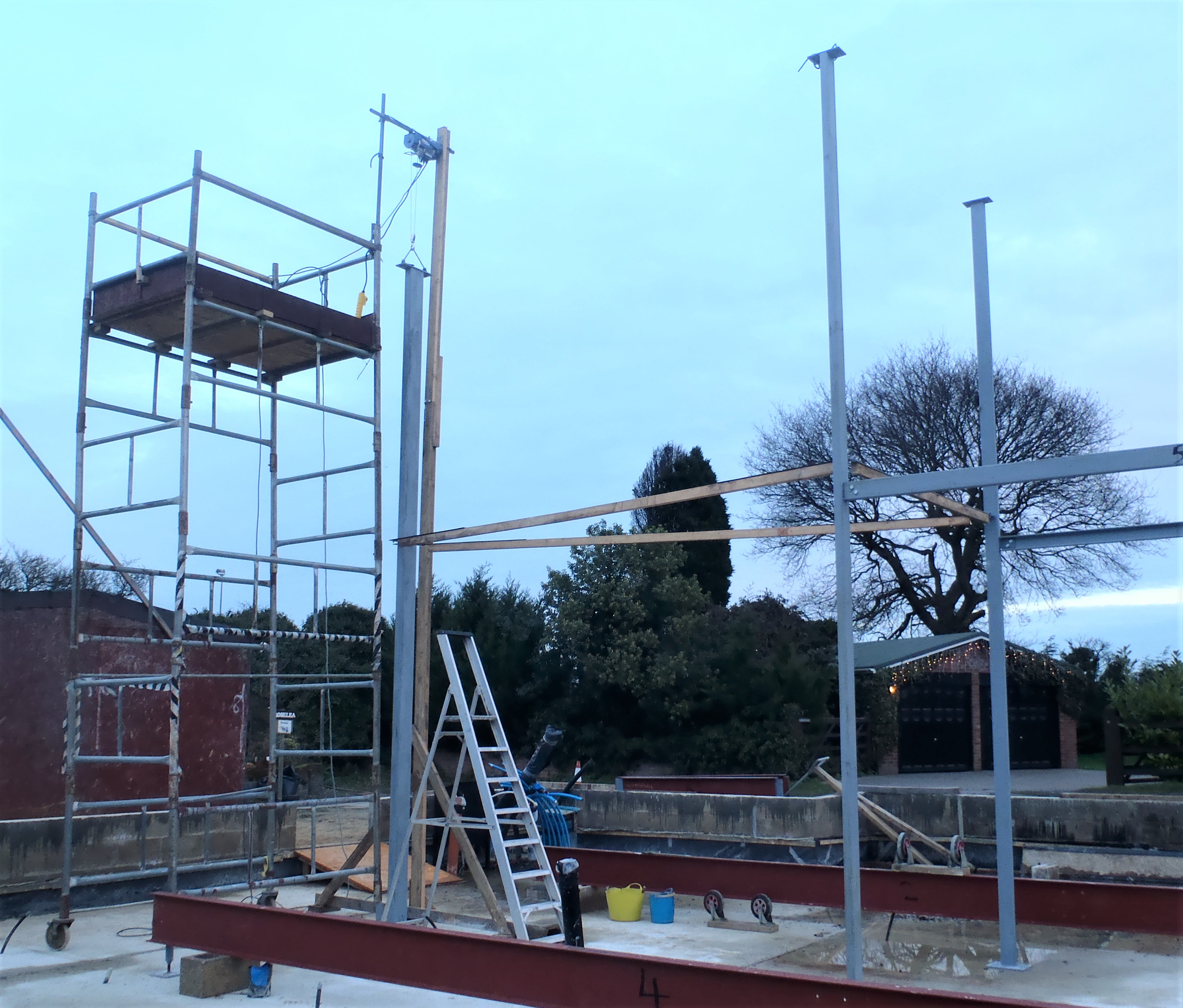
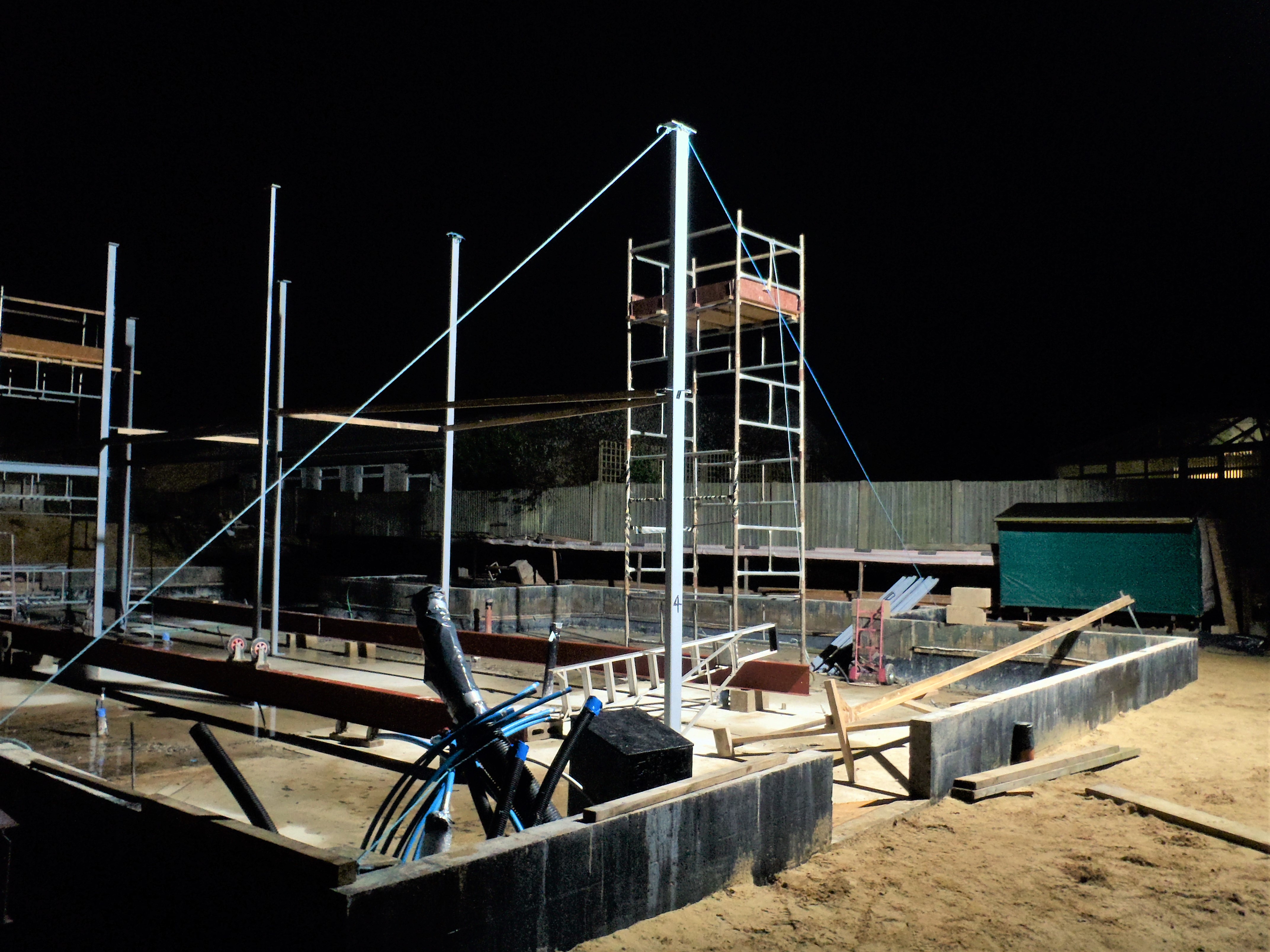
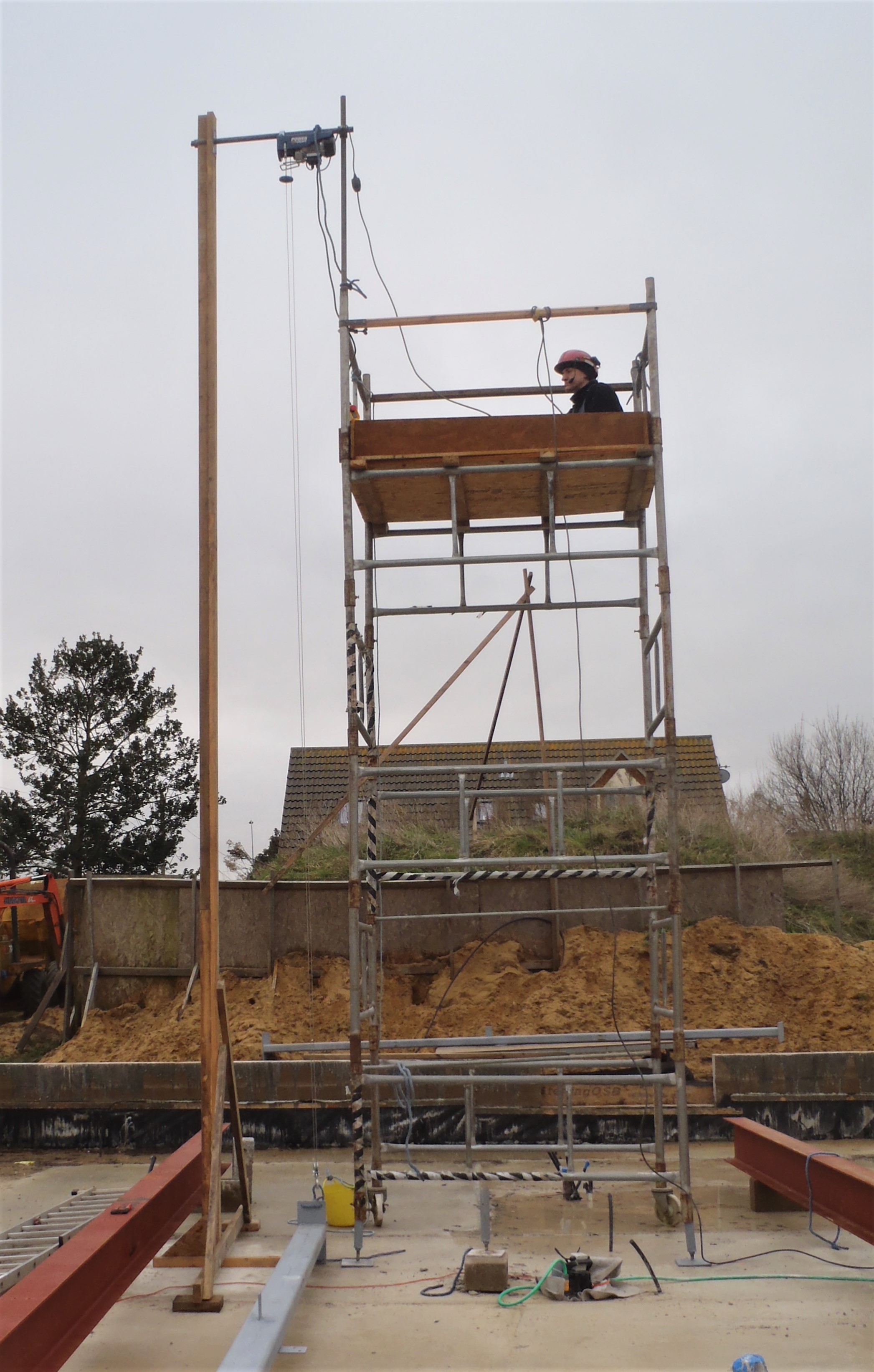
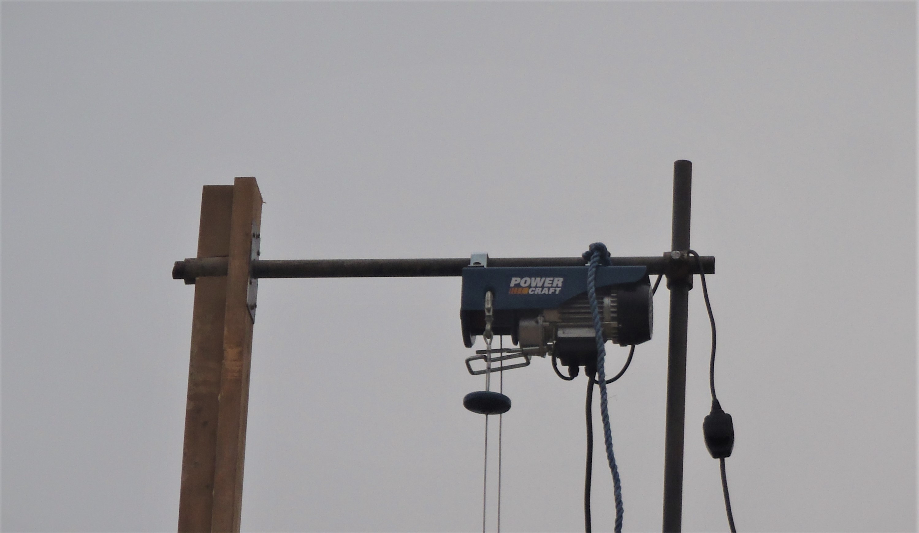
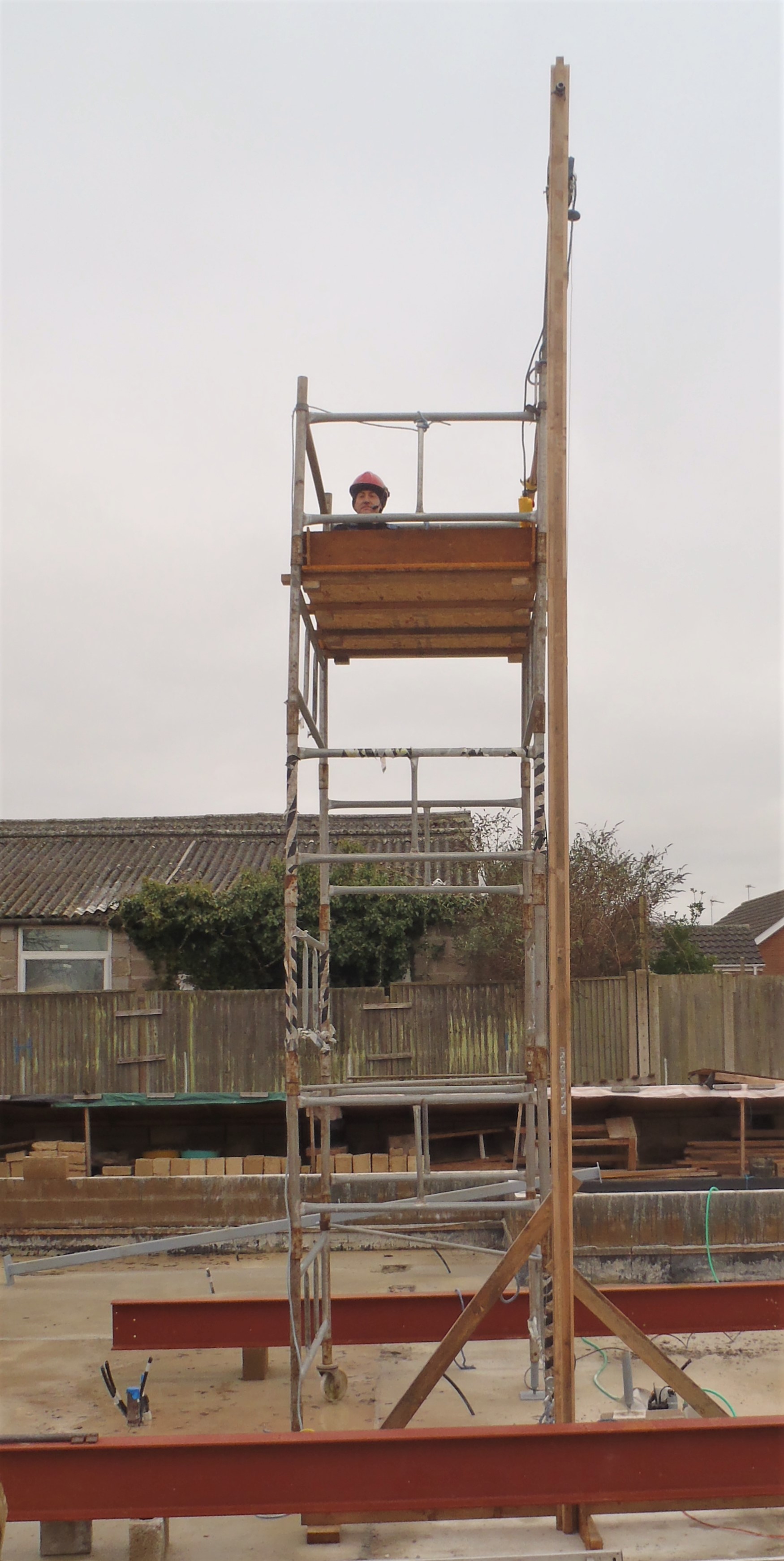
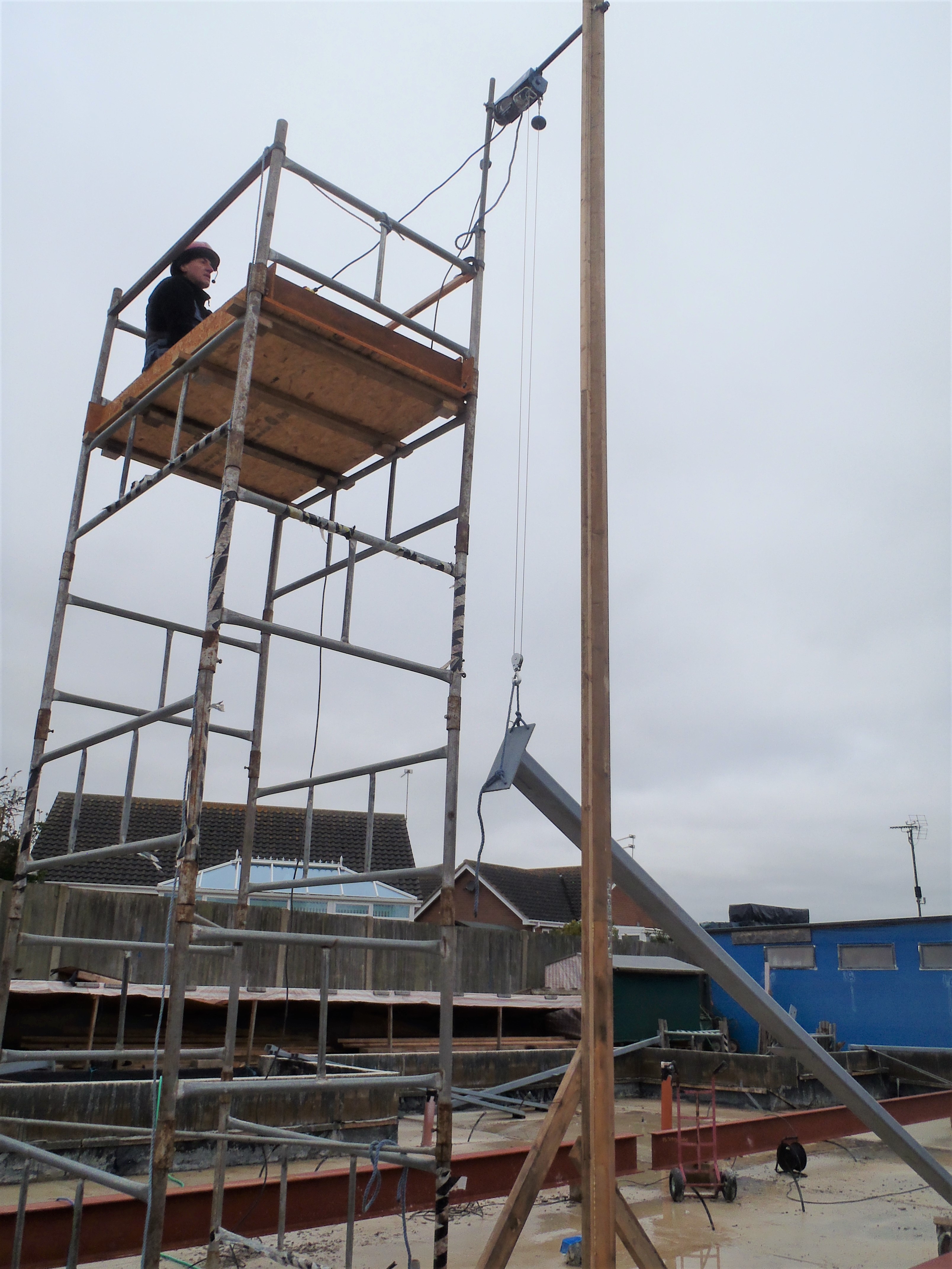
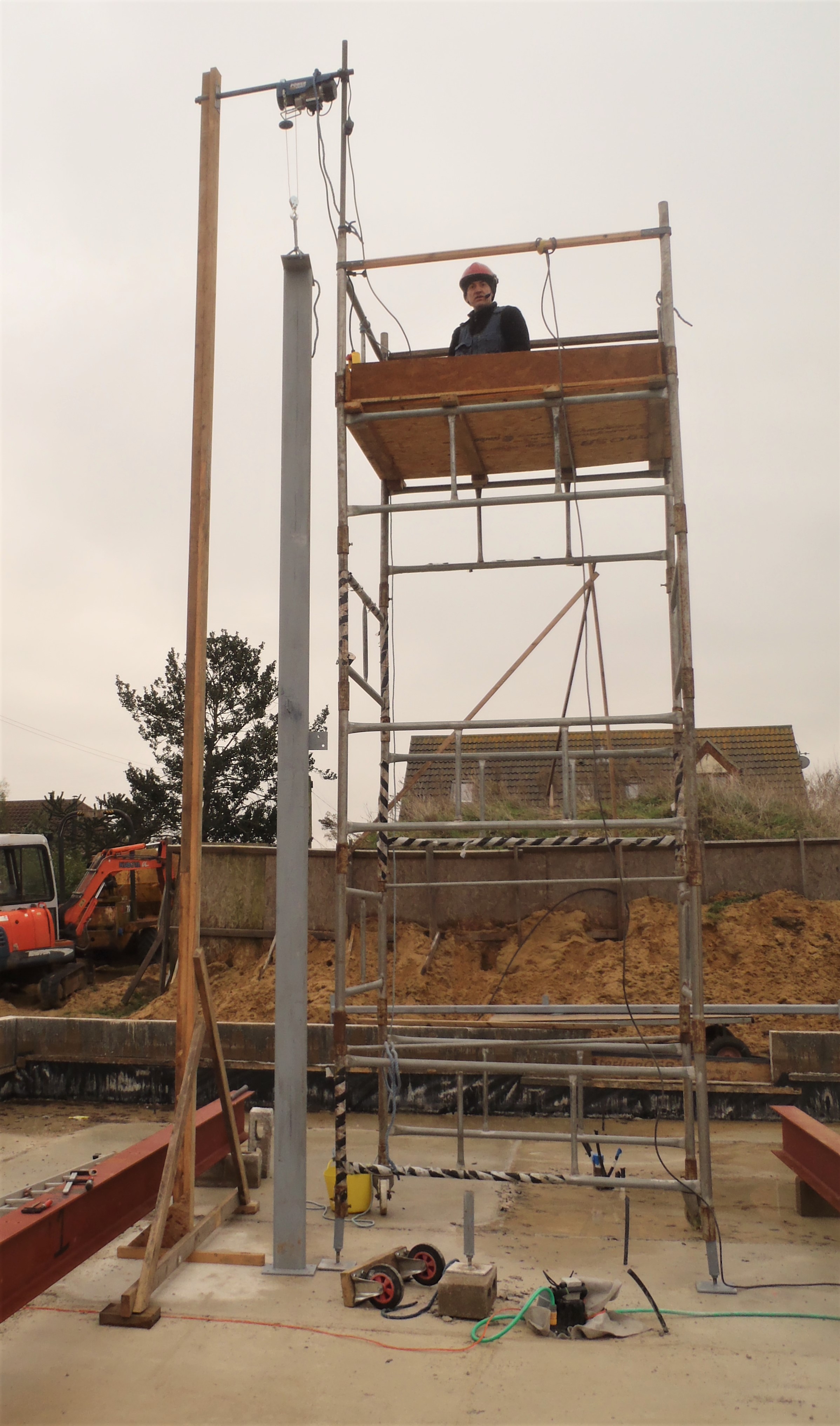
    We finished off the crane this morning with the insertion of the metal socket plate at the top of the wooden crane leg. Then we attached a long arm at ground level with two feet at each end and diagonal struts from these ends and screwed to the vertical section of the crane.

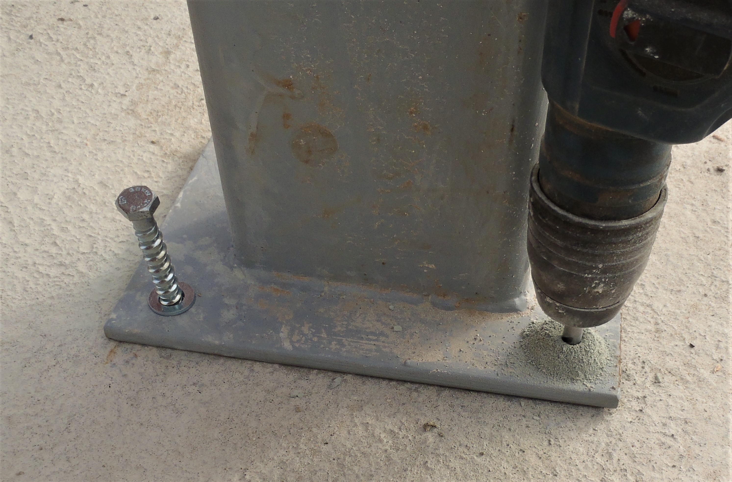
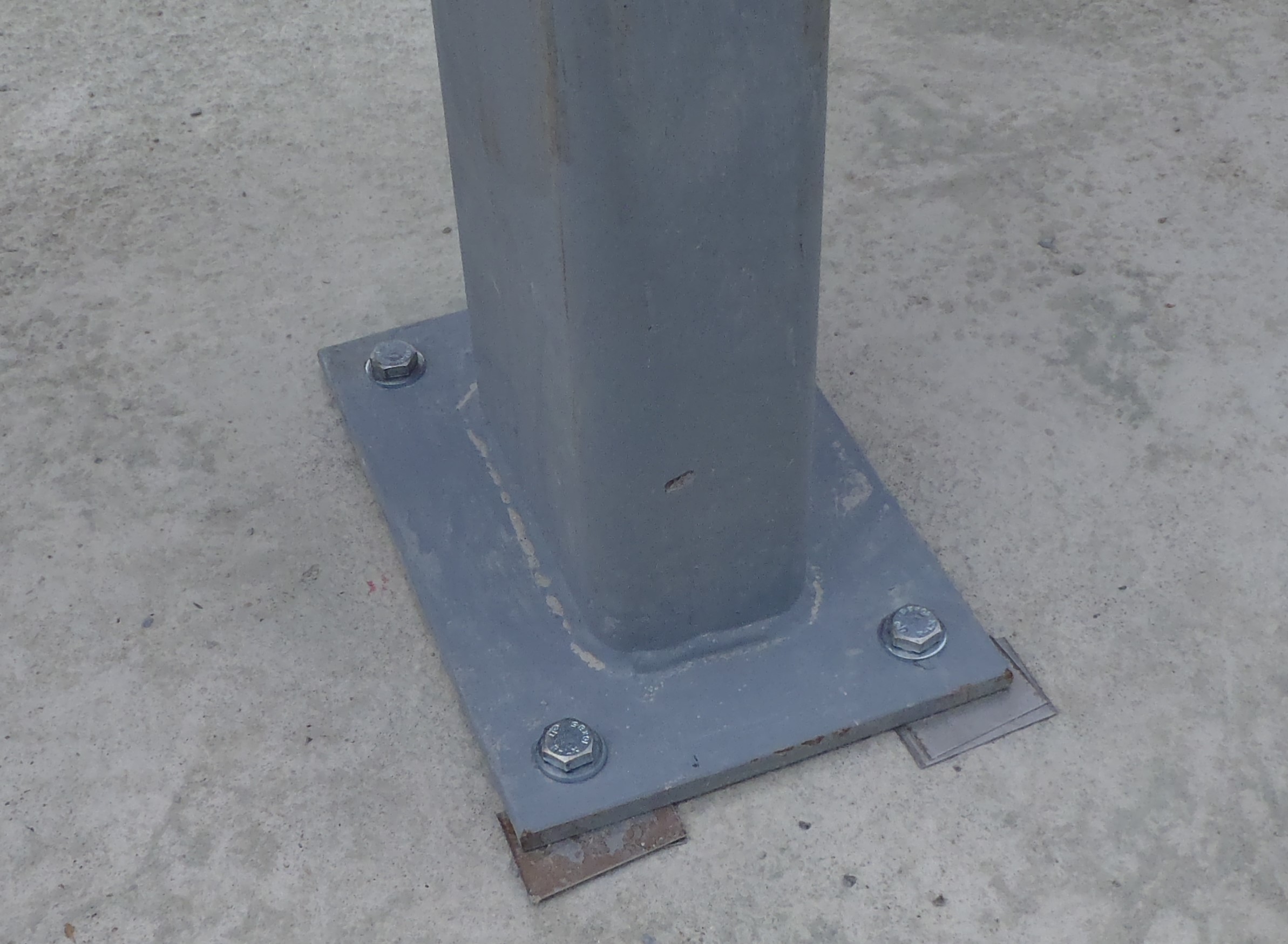
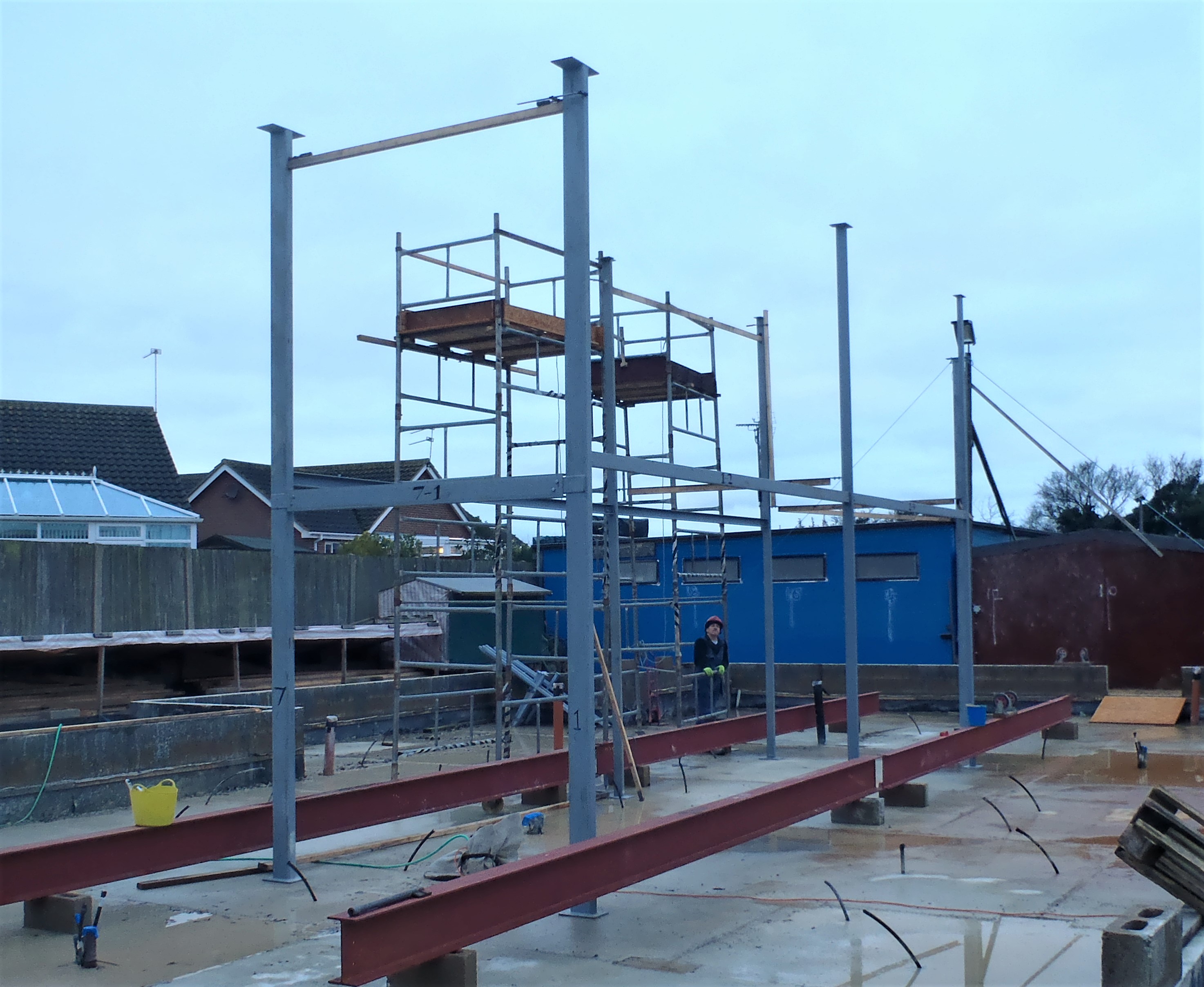
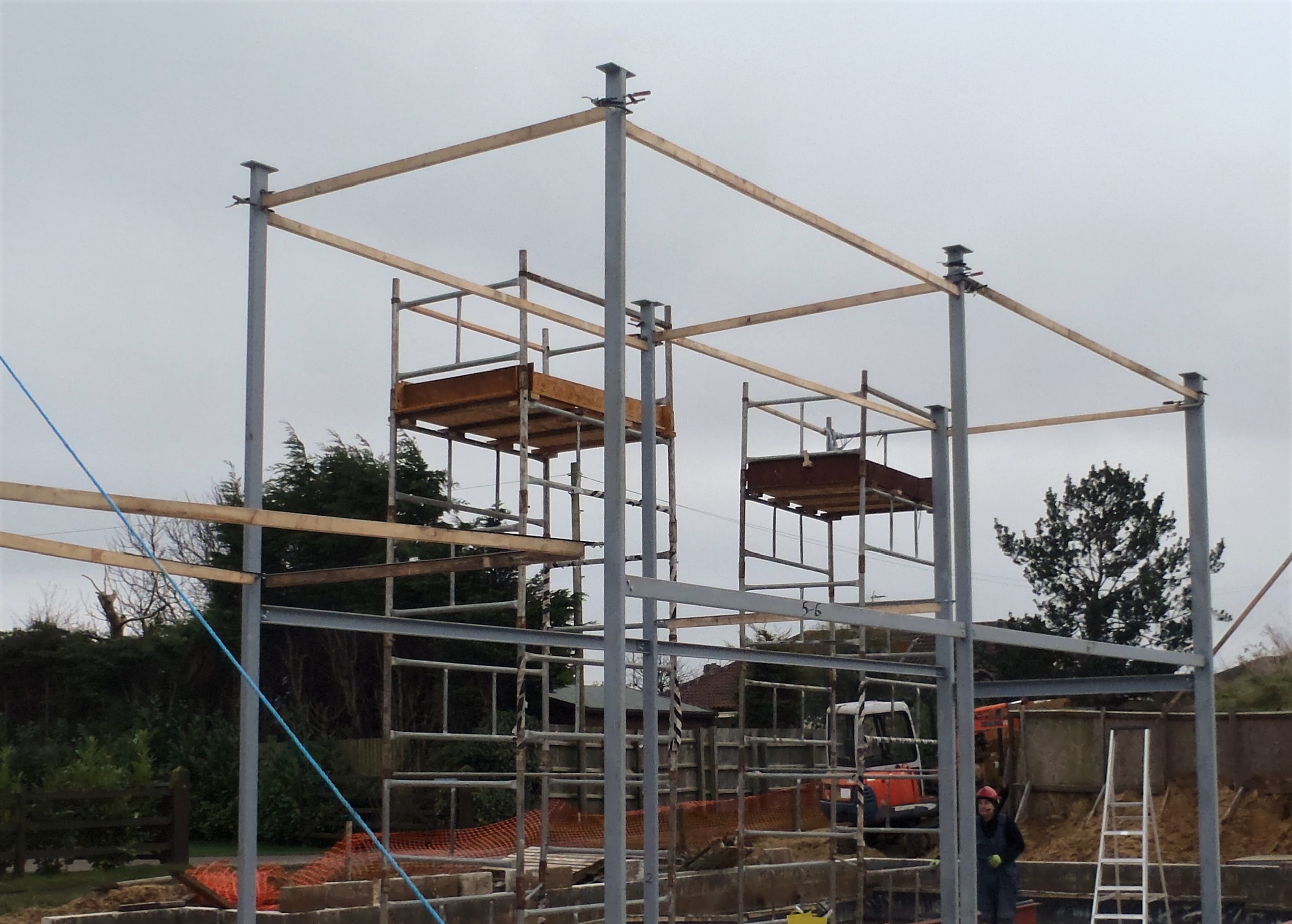
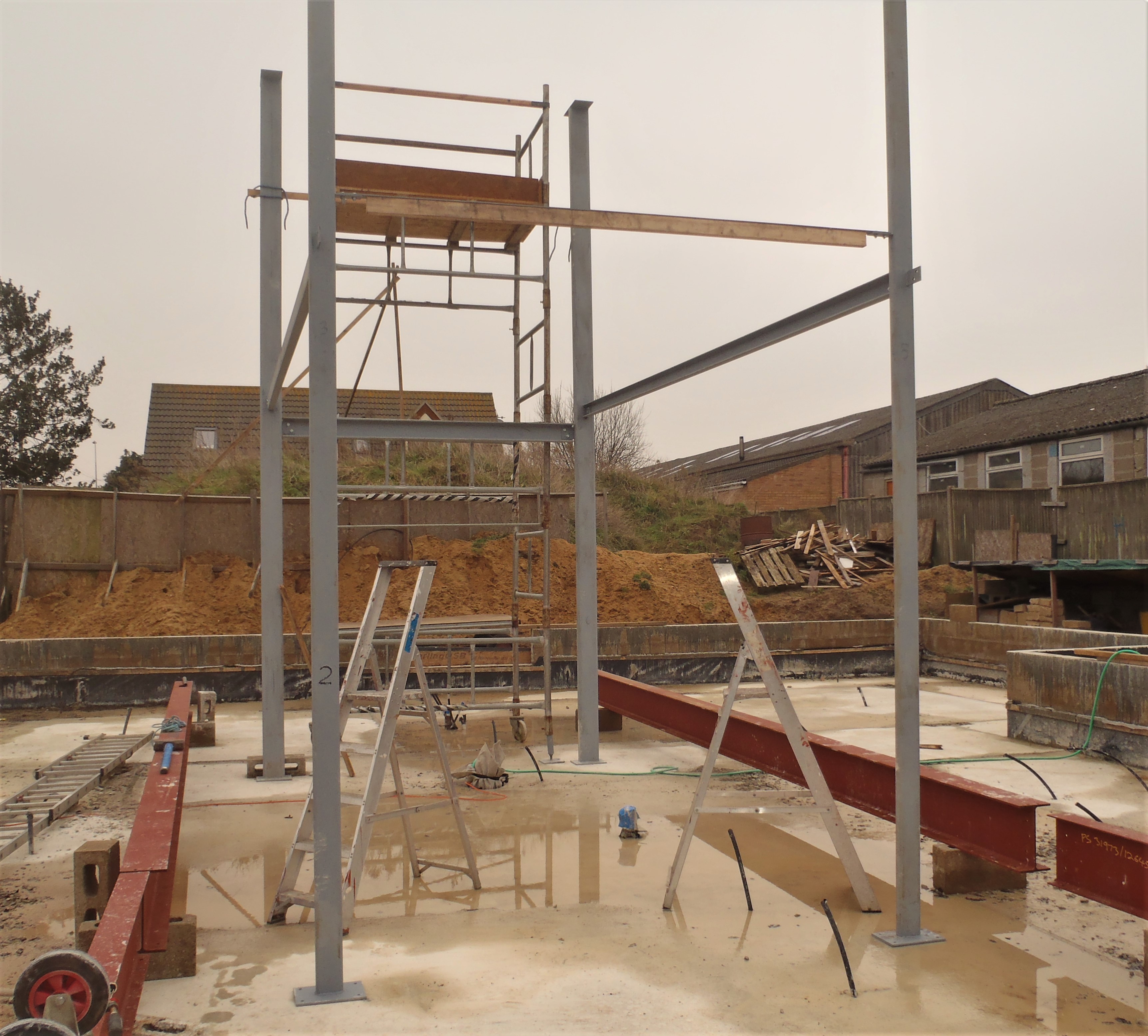
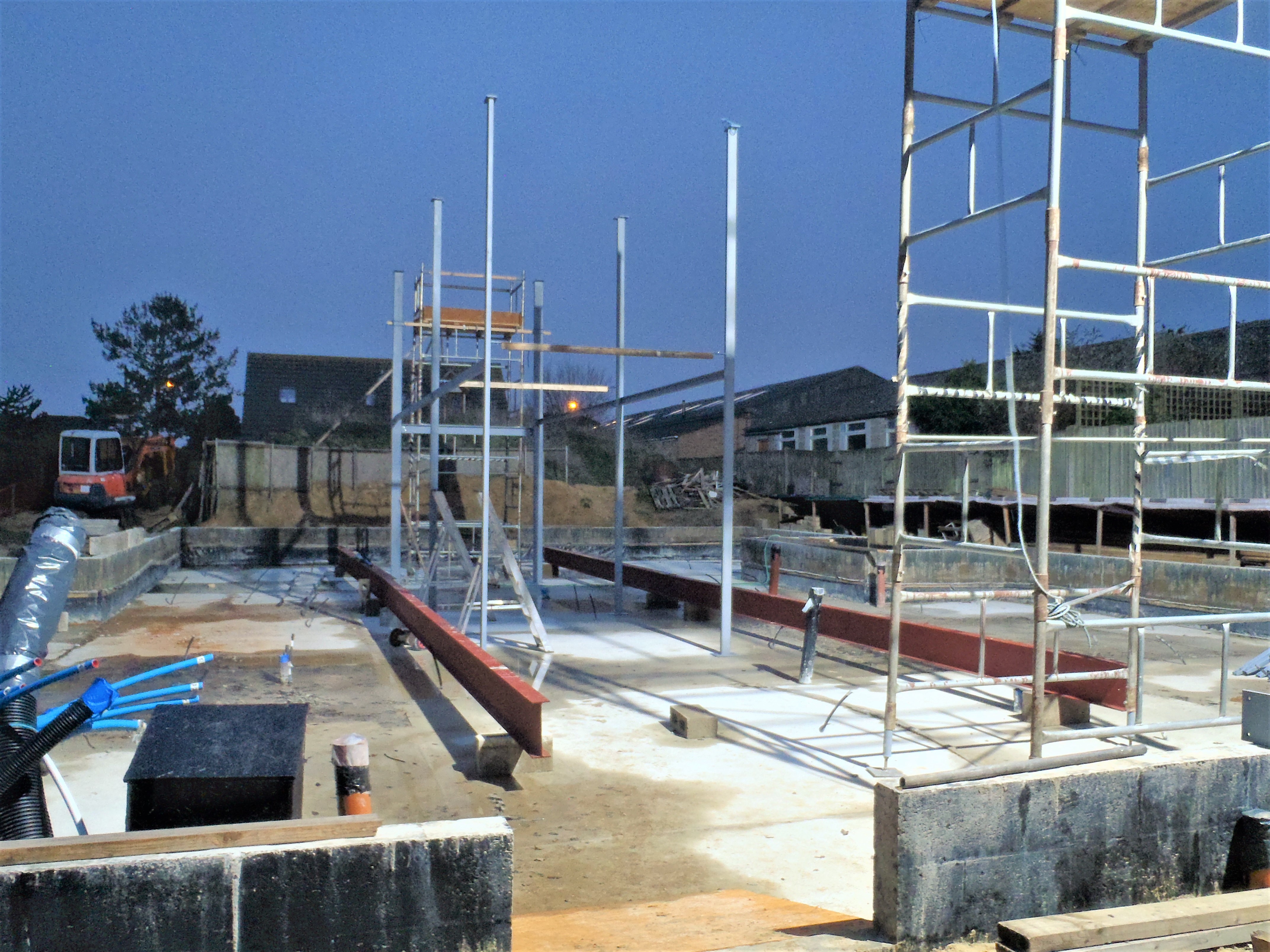
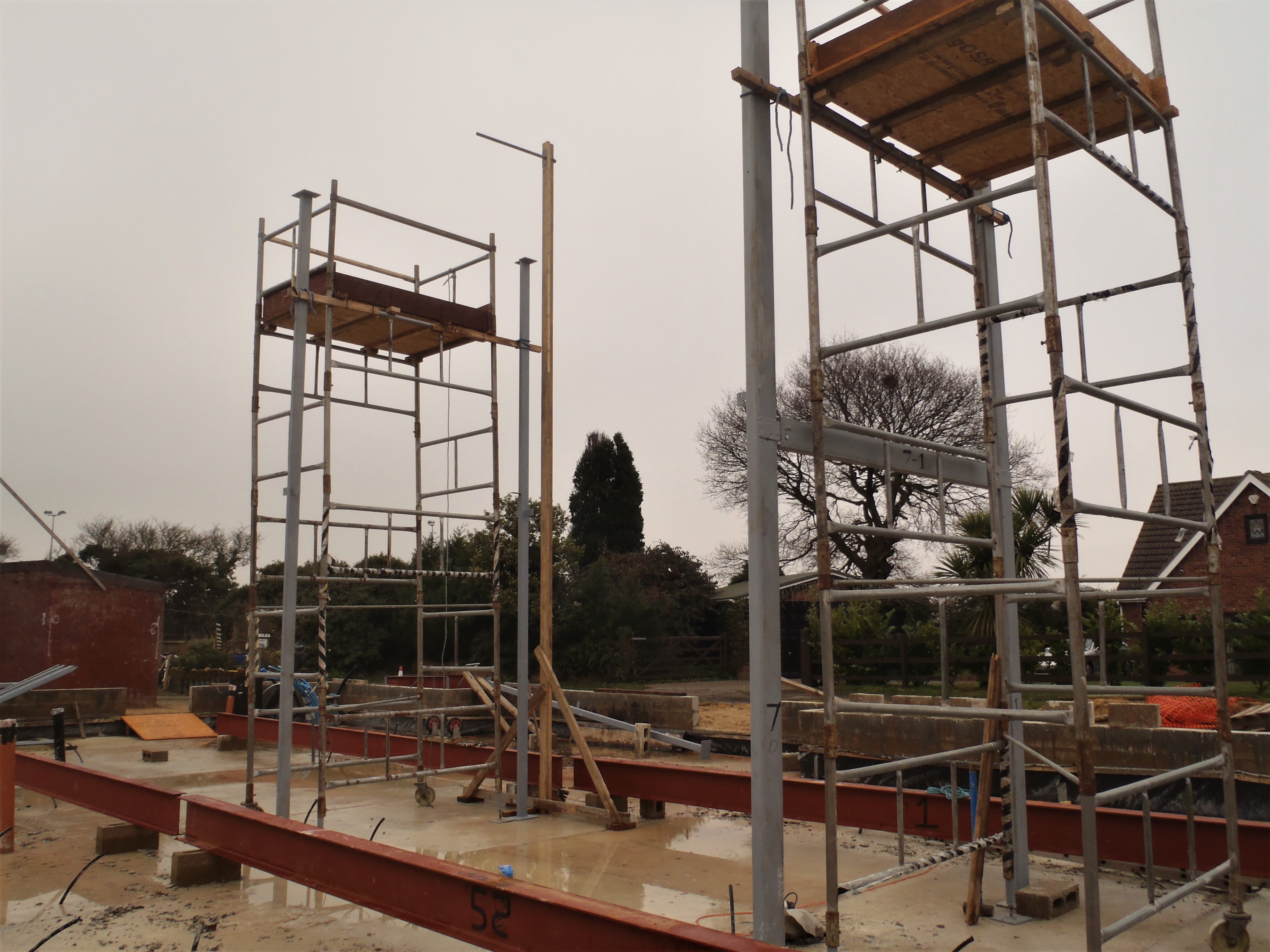
    Then, we went to finish off the Steel leg number 3 (our sixth leg we are bolting down) and try to understand why this leg has a slight tilt on it. we went to the top of the scaffolding tower (oh yes, we also attached our long extending ladders to the towers and it is much much easier and safer to climb up to the top now!) and measured the distances between Leg 1 and Leg 2 (4775mm – correct!), at the bottom (4775mm – correct) and then between Leg 2 and Leg 3 at the top (3714mm – correct) and at the bottom (3710 – oops!!!). We have found the error and it is nothing we can do about it as we have already drilled the 4 holes into the concrete so we cannot move the bottom of the leg the required 4mm northwards to straighten up the leg. We will have to live with it and but the slight offset is so small (thanks goodness) and by the time the whole house is constructed, bracing everything together, it would not be a problem and will not show.

    We stopped early because of the strong winds out there as we have a heavy storm thundering pass somewhere else hundreds of miles away but tomorrow, it may be much calmer so we will begin the task of raising the big steel I beams and plonking it on top of the legs!

  • Second Crane Leg Built

    With only half of the work force in the morning and normal strength for the afternoon, we constructed the second wooden Crane leg we will need when we are lifting the long steel I beams.

    The various metal collars, sockets and the main upright arm were cut, drilled and have pieces welded onto them.

    Crane-Metal-Hardware

    Crane-Metal-Hardware

    Then, the long wooden leg was put together, using similar timber pieces as last time, but we added extra reinforcing pieces to overlap the joints. This was all glued and screwed together and left overnight to set and cure, hence why we were late finishing at 6:40pm!!

    2nd-Crane-Leg

    2nd-Crane-Leg

    So tomorrow, the last little job is to bore a large hole at the top of the leg to fit the socket with the plate on it to form the holder for the vertical pole that holds the hoist machinery on that makes our homemade crane.

  • The Main Six Legs Are Bolted Down

    We continued the work of setting the legs to be in their absolutely correct positions and bolting them down.

    We are using a special bolts which ‘self tap’ into concrete, see below

    Concrete-bolts

    Concrete-bolts

    The ones we are using are 12mm in diameter and 90mm long. We use a masonry SDS drill with a 10mm drill bit to bore down into the concrete and then blast out the rubbish using compressed air.

    Drilling-a-bolt-hole

    Drilling-a-bolt-hole

    We started at the Great Room end at Leg 7, doing the holes etc. and then sliding thin metal strips under the edge of the foot plate as needed to adjust the leg to be straight up and then tightened down the four bolts to lock down that leg.

    Leg-one-bolted-down

    Leg-one-bolted-down

    We then continued onto leg 1 and did the same set of tasks there, and then proceeded to leg 2 and leg 6. We measured the direct distances between the legs in all directions plus also the two diagonals to make sure the whole structure is at right angles and following a straight line (as we got very long I beams crossing along the top of these legs). We didn’t have to do very much adjustment to the absolute position which was rather rewarding for us and reflects on our effort last week when we first installed the legs.

    So leg 2 and leg 6 were similarly bolted down and adjusted for verticality and we then moved to the final pair of legs, number 3 and number 5. We did our distance checking again and with a bit more adjustment this time (but only approximately 15mm movement) we got these two legs into position too. It was now getting dark and we got leg 5 all bolted down and balanced with the leg set vertical but we couldn’t finish leg 3 as it was too dark to see the bubble on the spirit level and also there was a slight odd situation where this leg is not very vertical and is leaning a little too far towards the garage end of the house. the bottom distance is correct at 3714mm apart and we know the previous leg (number 2) is vertical but something is wrong. We will check the temporary horizontal wooden strut between the legs at the top to see if it is the same distance and try to find the answer .. but tomorrow in the daylight after lunch – grin!

    So in conclusion, we managed to bolt down all six legs and check five of them to be proudly  standing upright, just the final leg to finish off and then we will be ready to start lifting the huge steel I beams on top of them!!!!

  • Installing Temporary Adjustment Struts at Top of Legs

    In the morning, we spent making 7 wooden struts with metal tabs on the ends to control and bring together the distances at the top of the six legs that are having the four giant I beams placed on top of them.

    We made right angled metal brackets using 3mm steel plate, cut into 35mm wide by 120mm long and bent 30mm in from one end. Two screw holes were drilled so we can fix it down on the ends of the 63mm CLS timber pieces.

    This took all morning to do.


    After lunch, we went around .. and around .. and around .. putting up each of the seven struts, one by one, by climbing the scaffold tower each time. Phew!

    It was the case of moving each scaffolding tower around all the six legs so each strut could be reached and clamped using gluing screw clamps or squeezy racket clamps to grip the struts at the top of each leg.

    Two-ties-in-place-by-4pm

    Two-ties-in-place-by-4pm

    What a merry dance around the two scaffolding towers had!

    We finished in the dark, at last, and so each of the six legs and the connections to their neighbours are now controlled, with the distance is set correctly according to the drawings.

    Tomorrow, we will check the verticality of each leg and make adjustments to ensure each leg is fully vertical by sliding thin pieces of steel strips under the foot and then drill the holes down into the concrete and drive self tapping concrete bolts, and that will stiffen up the movement of the legs significantly .. we hope!! – Grin!

    6-legs-tied-at-the-top

    6-legs-tied-at-the-top


  • Seventh And Final Leg Is Standing Proud!

    On a rather warmer day, we got the seventh and final steel leg hoisted and positioned in the required place.

    We prepared for this operation by making two bracing beams using a couple of 63mm CLS timber pieces with metal strips screwed on each end to provide the anchorage. These bracing beams are only temporary to hold this leg in place while we make further precise measurements to each and every leg before we bolt them all down into the concrete.

    This final leg is our third heavy duty version (weighing 160kg) and it all went just fine with no signs of tension or trouble with our repaired crane wooden leg.

    Leg-7-in-place

    Leg-7-in-place

    We verified the position of the previous pair of legs (number 3 and 5) to make sure they were in the correct location (only needing a slight adjustment) and then we were able to put on our bracing beams from those legs to our final leg to secure it and hold it stable. But we were concerned with a potential mishap if we had any strong winds and it may have caused  a possibility of pushing this leg (number 4 it is) over sideways so we tied two lengths of rope and anchored back to the concrete wall (just like tying down a tent with guy ropes).

    Leg-7-with-guy-ropes

    Leg-7-with-guy-ropes

    We then went back to the first pair of legs to start the exact process of measuring distances and angles to confirm the positions of the legs against the drawings. We used a laser beam to project right across from the Kitchen front wall, skimming pass the two steel legs and reaching the other side of the Great Room. We then measured from each corner of the Great Room to the laser beam and both were very, very similar (5564mm) and the gap between the laser beam to the side wall of the extension was 40 to 50mm which conforms very closely to the plans – phew thank goodness for that!

    We then made sure that the distance between the legs (number 1 and number 7) were the same at the bottom and at the steel lintel (measuring 2327mm) which is within 1mm of the precise number off of the drawings.

    But we were concerned about the verticality nature and our digital spirit level was saying 89.85° for these legs and we wanted to make sure that both were 90°. For every 0.05° out, then there would be an offset of almost 5mm (precisely 4.8mm) at the top compared with the bottom, therefore that 89.85° value would indicate that the top of the leg would be over 14mm further apart compared  with it’s neighbouring leg and our steel cross struts wouldn’t connect together and allow our bolts to go into the holes!!

    After some discussion, we came up with the idea of clamping pieces of timber between the legs at the top at the exact distances so that we can be reassured that the bolt holes will line up with the I beams and the cross struts when they get hoisted into place.

    All this careful considerations was needed because we want to drill the mounting holes into the concrete to bolt down the foot plates of our legs and have them much more secure and stable before we haul up the very heavy I beams on top of them! But of course, if we bolt down the legs and then find that the tops are NOT in the correct positions and we couldn’t line up the bolt holes and locked the pieces together .. we would be rather annoyed! Hence why the deep thinking and discussion session we had to solve this problem. We will implement our solution on Monday – Phew!

  • Third Pair of Leg Are Up and Connected

    This morning, in a freezing strong wind, we connected the second pair of legs (number 2 and 6) back to the first pair (number 1 and 7) using U Channel steel elements. They are 4.77 metres long of a u shaped piece measuring 100mm high by 50mm wide and made of 8mm thick flanges on the top and bottom edges and the vertical webbing is 5mm thick. They weighs just about 50kg each.

    Then, we put between the second pair of legs a thin metal strip to tie the legs together. This strip would normally be screwed down into the first floor joists but that isn’t in place yet!! This strip is 2.4metres long of a 5mm thick steel by 50mm wide. It was screwed onto a piece of 63mm CLS timber to help in lieu of the floor to stop it buckling if the legs tried to lean into each other.

    Four-legs-up-and-connected

    Four-legs-up-and-connected

    We finished off the morning work by moving along the scaffolding tower to the next pair of legs to do.

    After lunch, we hoisted up the third set of legs (number 3 and 5), these being also of the light duty square box steel measuring 100mm by 50mm with 5mm wall thickness. Each of these legs weighs 65kg. it was blooming chilly, well freezing actually, in the strong breeze up there on top of the scaffolding tower!!

    Next we hauled up two more U channel steel beams to connect these legs back to the previous legs (the second set, number 2 and 6). These horizontal steel pieces were the same specs as the previous u channel shaped beams used, so we now have a continuous connection from leg 1 to leg 2 and onto leg 3 and the same on the other side from leg 7 to leg 6 and on to leg 5.

    The final job was to put the tie strip between these third pair of legs, just like last time.

    Six-legs-up-and-connected

    Six-legs-up-and-connected

    We did have one incident at this point, the wind picked up a bit and blew over our tall wooden crane leg and caused some minor damaged two thirds the way up. We had moved it out of the way and it was sitting on its spreading out support arms but there was enough strength in the wind to knock it off balance (especially with a metal bar unbalancing it at the top) and it came crashing over and landed across one of the steel I beams and ramming the steel bar down onto the concrete slab. Fortunately, we were not in the way of this crash!.

    We finished off the afternoon by moving the scaffold tower over to the final position for hoisting up the seventh and final leg, which we will tackle on Saturday.

  • Next Two Legs Goes up!

    It wasn’t so bad today in regards to ice, there were still patches of ice here and there but they were just melting and breaking up as soon as you stepped on it.

    So we started the day by adjusting the position of the first two legs (the heavy duty ones at the Great Room end) and got them almost exactly in their correct positions.

    Next, we assembled the crane and hoisted up the next two legs, which are the lighter duty steel legs positioned at the Kitchen and Hall boundary, and hauled them into the correct point of the concrete.

    Legs-3-and-4-Up

    Legs-3-and-4-Up

    We stopped for a late lunch and the afternoon, we will be spent doing other tasks, so we will continue tomorrow, Thursday morning.

  • Hurray! Two Legs Are Up and Tied Together!

    Yippee! The temperature overnight was warm, positively balmy at 5°C and the water lying around on our concrete didn’t freeze again and nearly all the remaining ice had melted by the time we started our work at 10am today.

    We brought out our new homemade crane mechanism and got it assembled and installed at the top of the scaffolding tower.

    First-leg-lift-ready-to-lift

    First-leg-lift-ready-to-lift

    First-leg-lift-the-top-of-the-crane

    First-leg-lift-the-top-of-the-crane

    First-leg-lift-ready-to-lift-2

    First-leg-lift-ready-to-lift-2


    We then attached the end of the hook which had the wire going down through its pulley and back up to the winch. This setup provides double lifting strength at half speed which is good so we can monitor carefully what is happening and be able to stop and reverse if necessary.

    So having tied the top of the leg to the hook, we started carefully lifting it up. The scaffolding tower was holding firm and was not moving, the long wooden leg as part of the crane mechanism was solid and showing no signs of distress so we carried on winding in the steel cable into the winch and finally got the whole leg upright and dangling from the winch all by itself. We then lowered it back into position on the X marks the spot!

    First-leg-lift-halfway-there

    First-leg-lift-halfway-there

    First-leg-lift-upright

    First-leg-lift-upright


    This steel leg is one (of 3) of our heavy duty legs weighing about 160kg and 5.4 metres long. It stood there on the concrete quite well and was pretty stable all by itself, but we weren’t taking any chances so we clamped a short piece of 2inch by 2inch timber horizontally onto the scaffold tower and the sticking out end was tied to the leg with rope, all this near the top of the tower as possible. That was that Leg done.

    After lunch, we repeated the whole process over again, moving the crane unit over to the other side of the scaffolding tower and then lifted the 2nd heavy duty leg up into place and got that one tied to a second similar support arm sticking out the side of the tower.

    Then we tied the two steel legs together using the steel U channel piece which will serve as the lintel over the Great Room entrance to the hallway. This lintel is 2.5metres long and it is 150mm high by 75mm wide with a flanges of 10mm! that piece of steel weighed 45kg as well!!

    (No picture I accidentally deleted it…)

    Finally, as to finish off the day’s work, we assembled the second scaffolding tower, put the wooden platform in place at the top and installed the safety bars and kick boards around the edge of the platform.

    We were working completely in the dark by the end, but were well lighted with our super-duper 300W LED flood light! Tomorrow we will get up the next two legs and get them tied together AND back to the other two legs we have already erected!! Yippee!

  • Repaired and Modified Scaffolding Platform

    Since it got dark and too cold to work outside, we carried on in the workshop to repair the damaged platform segment (this is the middle of the 3 segments that makes up the whole platform) which we dropped the other day (from the top of the scaffold tower  onto the concrete!). We removed completely the broken 89mm CLS timber from one side of the segment and cleaned off the old glue joint etc.

    We then put on a new piece of the 89mm CLS timber, 1400mm long, all sanded to remove old dirt, onto (glued and screwed) the 1st segment of the platform so that both platforms are now the same design and have the same method of assembly.

    We are now ready to build up the second scaffolding tower later on when we are lifting the very long and very heavy steel I beams!!

  • Crane Unit Completed

    We finished off building our little crane unit by making a hollow tube attachment welded on to a metal plate, this will hold the other end of the horizontal bar (that has the electric winch hanging off it). This piece will go  through the wooden support leg near the top.

    Crane-Top-of-Timber-leg

    Crane-Top-of-Timber-leg

    The tube is another piece off an old 2inch steel pipe, 100mm long to go through completely the wooden leg. A plate about 250mm high by 85mm wide had a large hole cut using the plasma cutter tool, in the middle and 6 small holes drilled around it for mounting screws. The tube was welded on and then the wooden leg had a large hole drilled through at about 200mm from the top to accommodate this metal tube and plate and help spread the load of the steel item being lifted up without running into the risk of splitting the wood!

    Then after a late lunch, we constructed various bracing elements for the bottom of our crane support leg using a beam (about 2.4metres long) of 89mm CLS timber mounted on two 2inch by 6inch timber blocks as feet. Another shorter bracing beam (made from 600mm of 2inch by 2inch timber) went cross ways reinforced with a triangular OSB board to stiffen the joint. Both were attached to the leg outside as we could no longer work in the workshop as the thing was getting too big!!

    Crane-Base-of-Timber-leg

    Crane-Base-of-Timber-leg

    We took the completed leg over to the scaffolding tower and pushed the whole thing upright on its bracing feet elements and it stands there all by itself and is quite stable .. so far!

    The last job as the daylight was disappearing, was to rotate the tower around and moved it so it was positioned outside the footprint of the 7 steel legs. We decided that it was too dark, even with our flood lamp switched on, to continue and it was getting very cold so we are going for the fresh start in the morning!