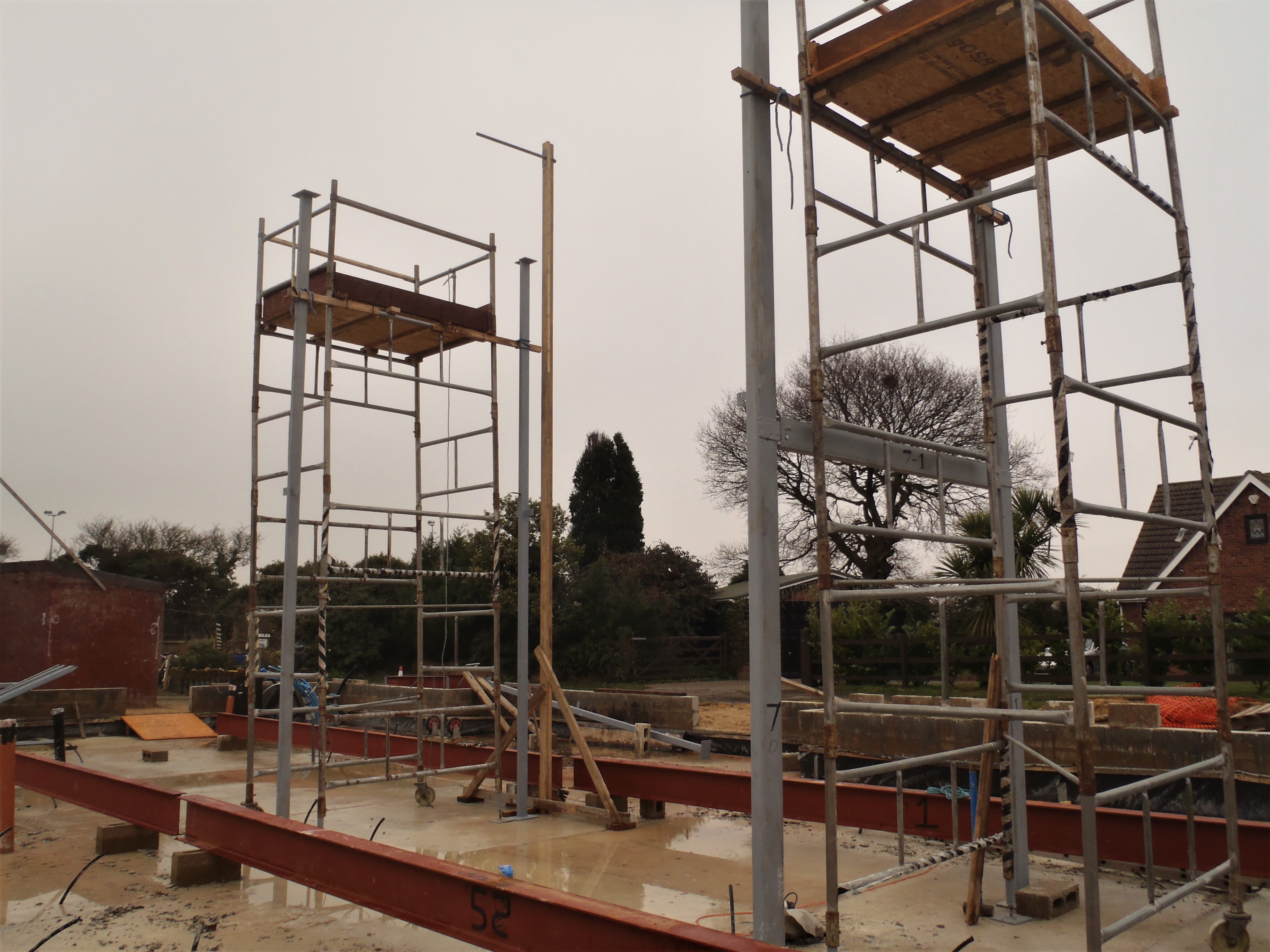
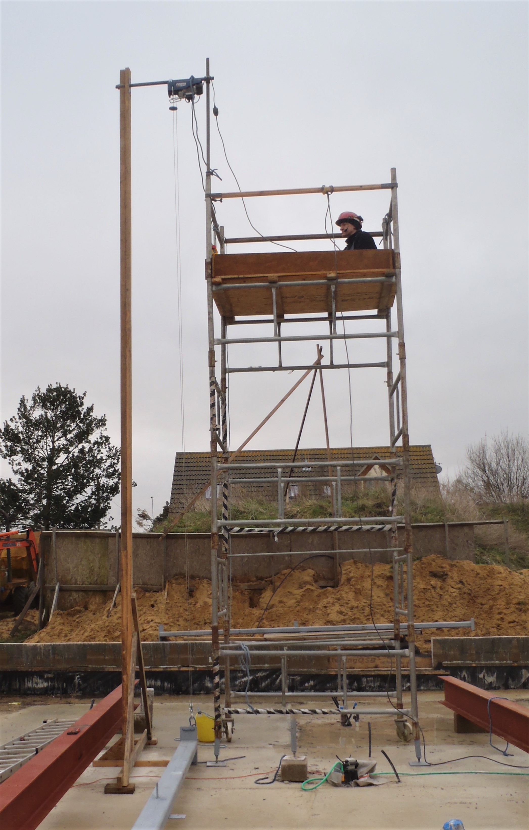
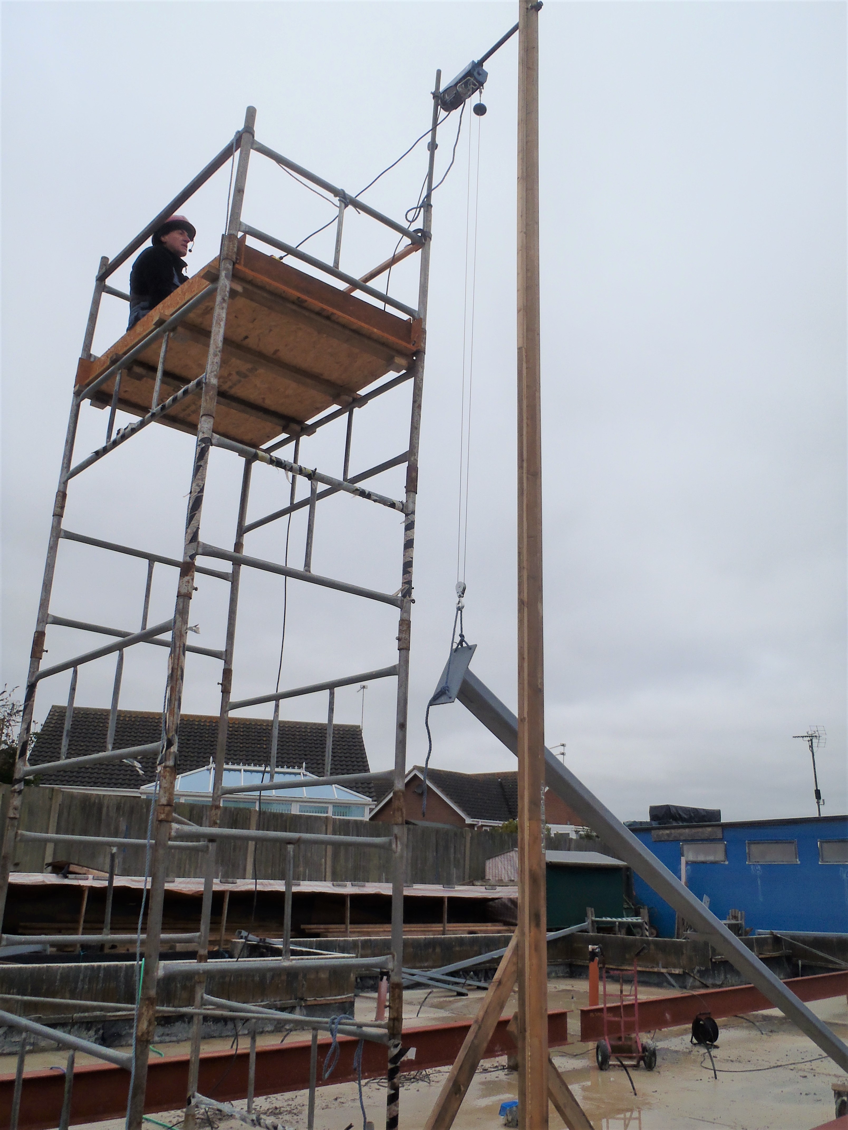
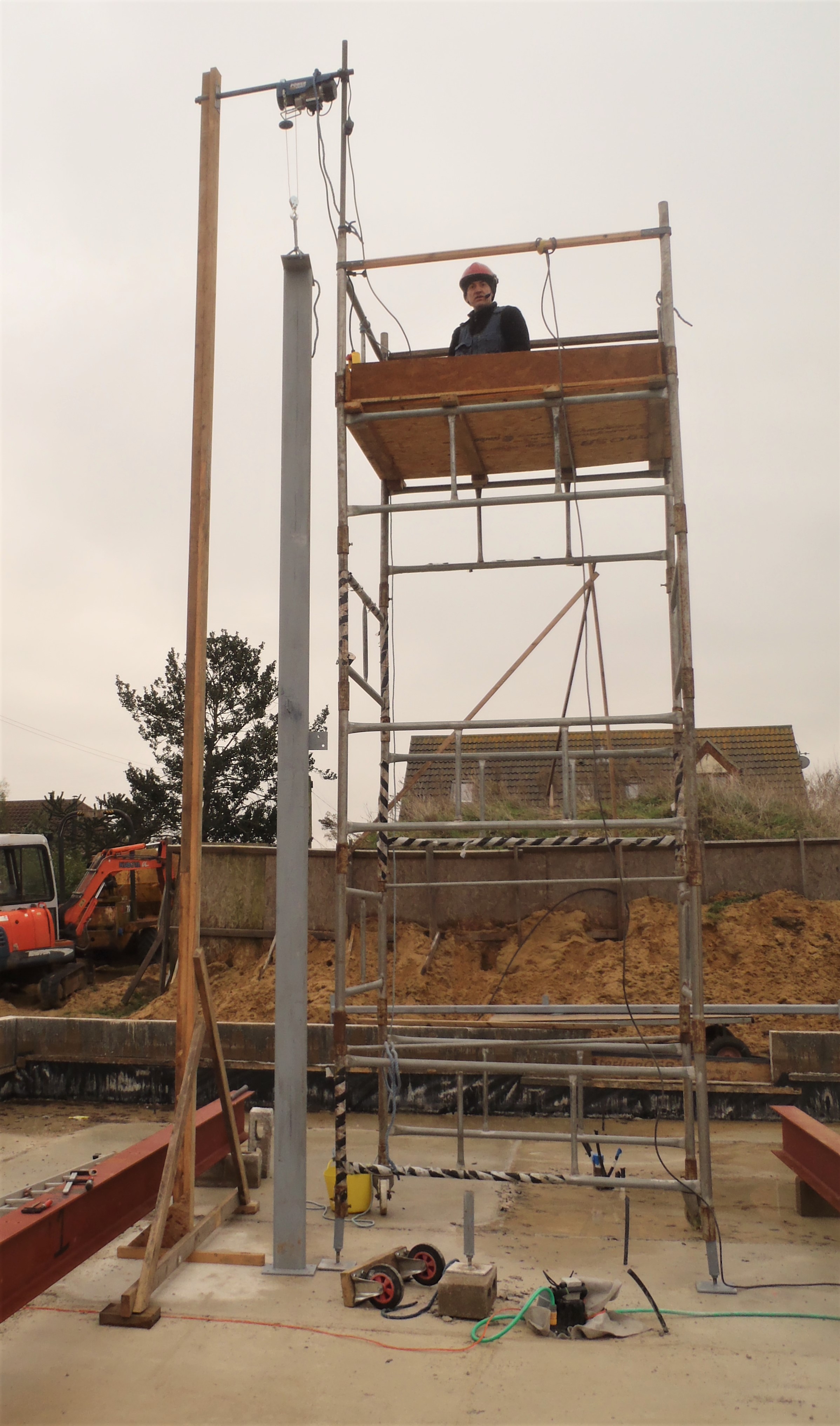
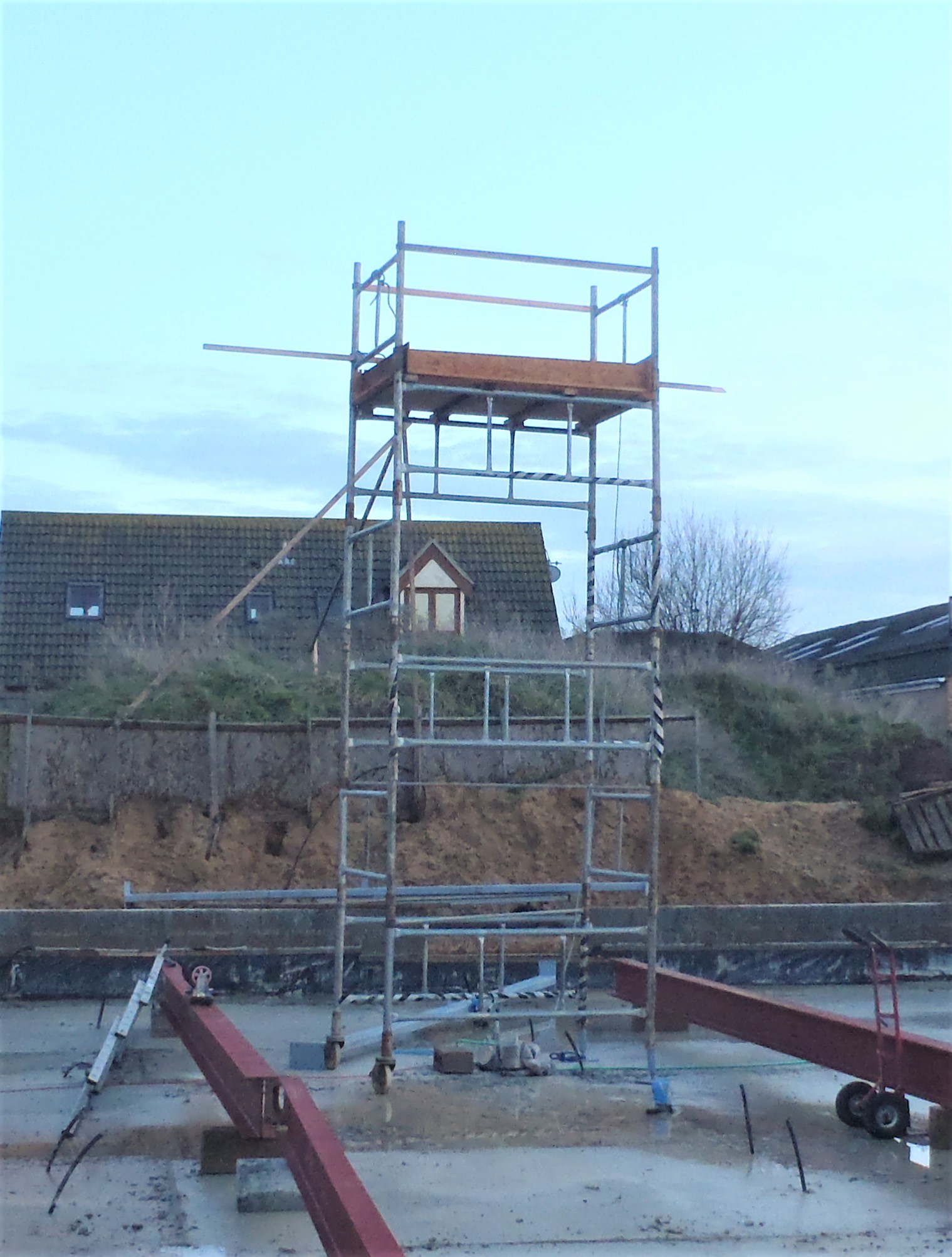
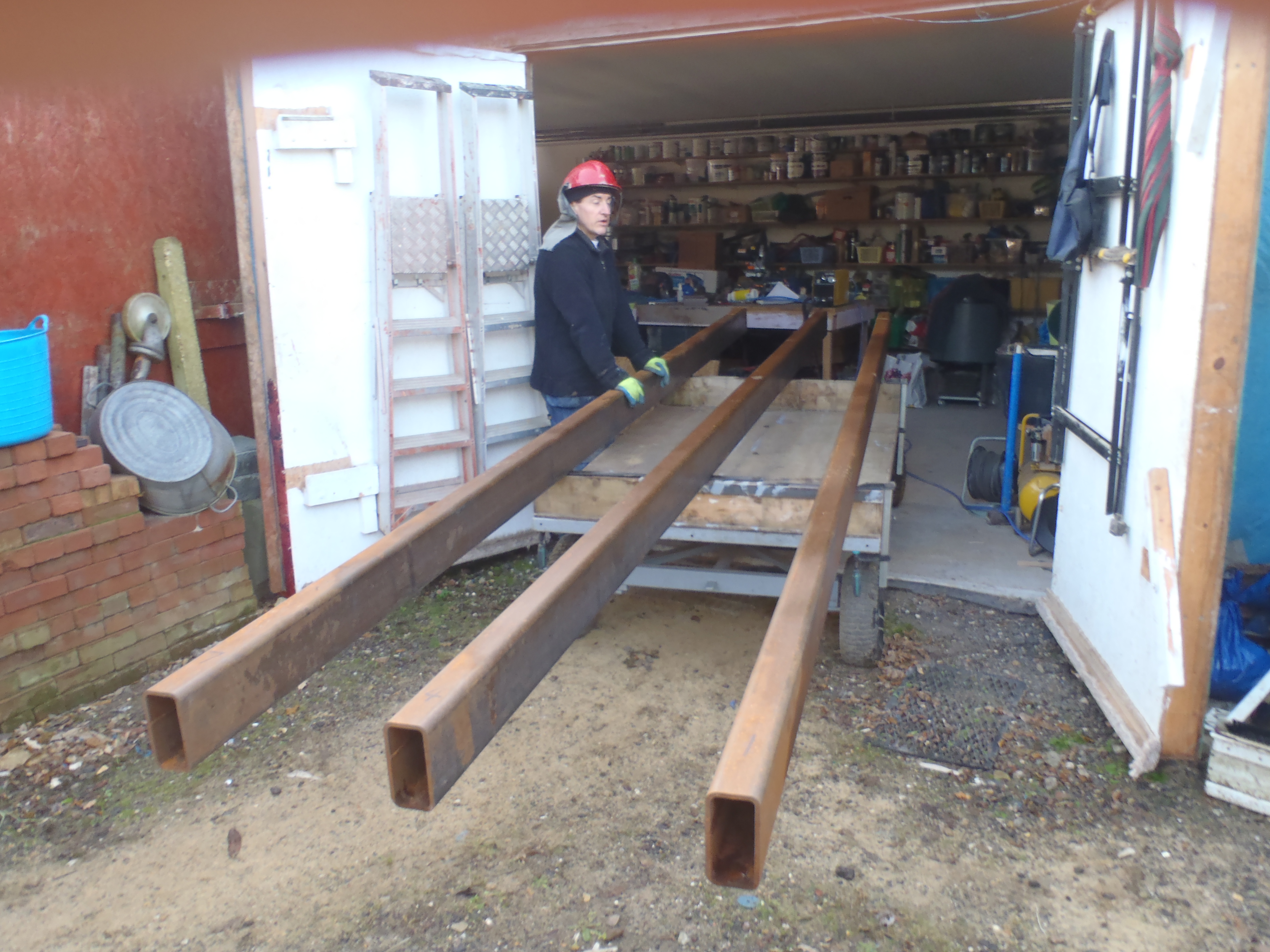
On a rather warmer day, we got the seventh and final steel leg hoisted and positioned in the required place.
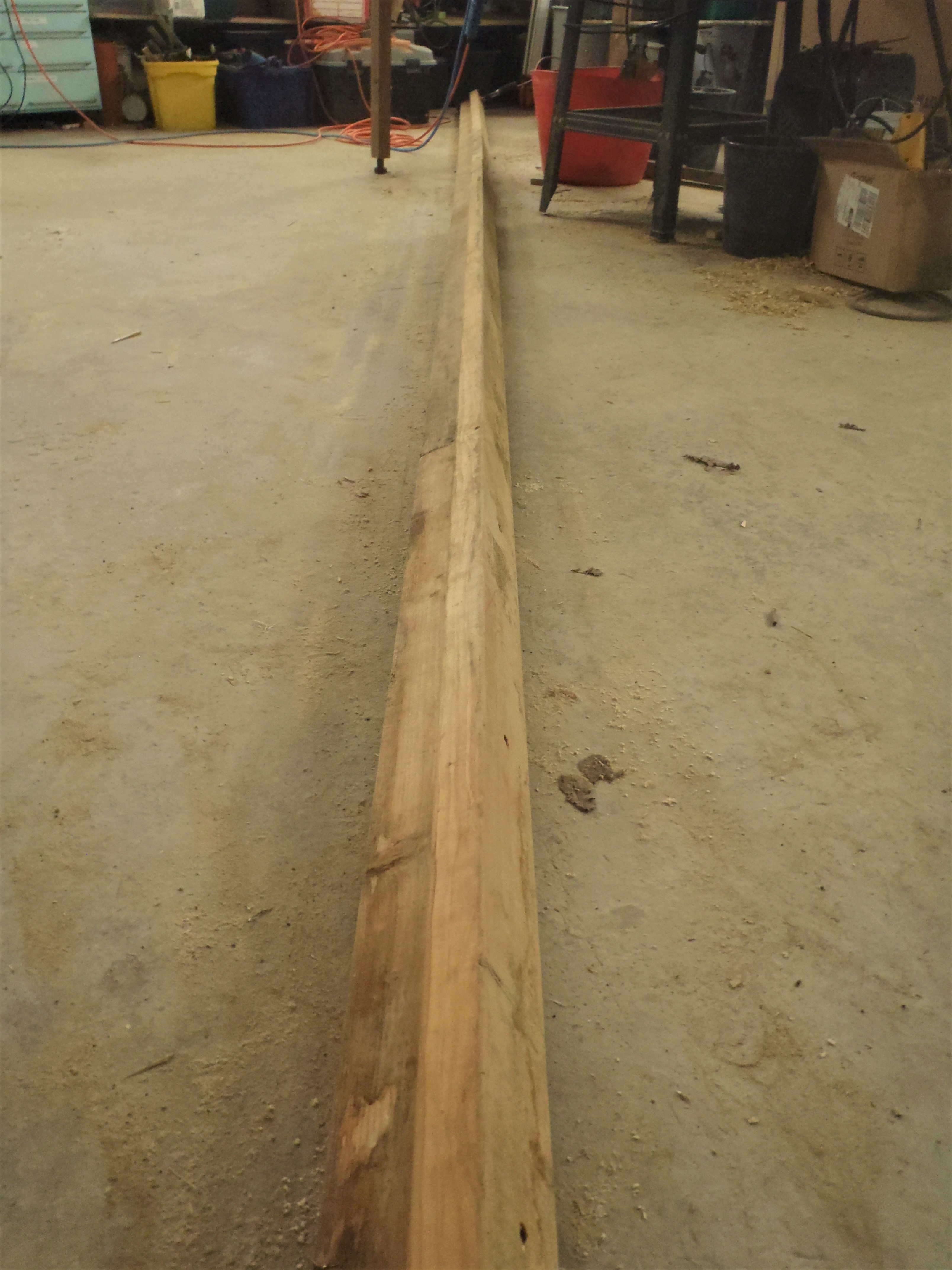
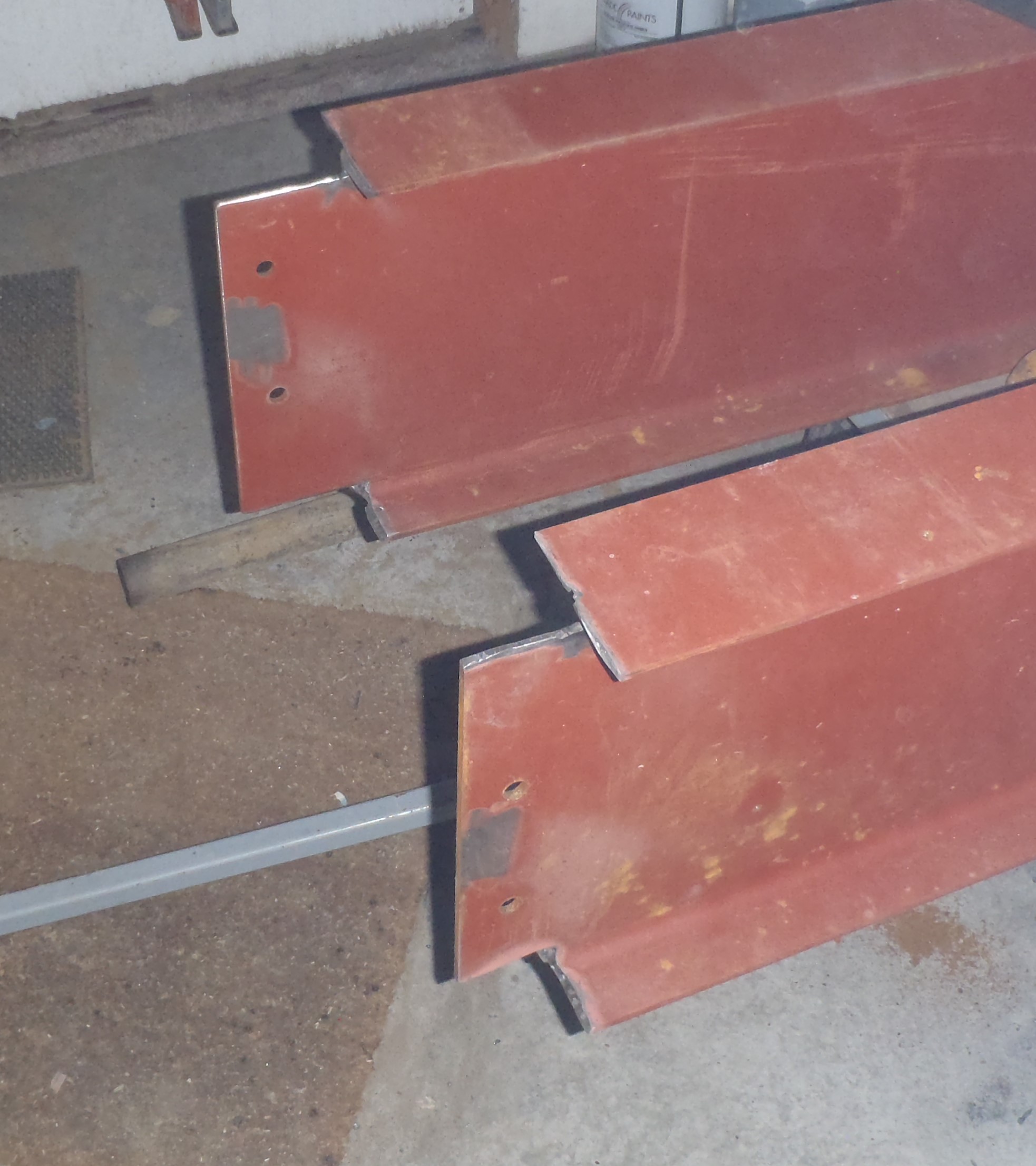
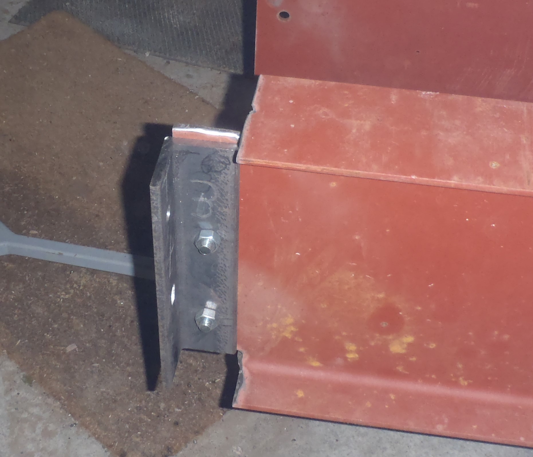
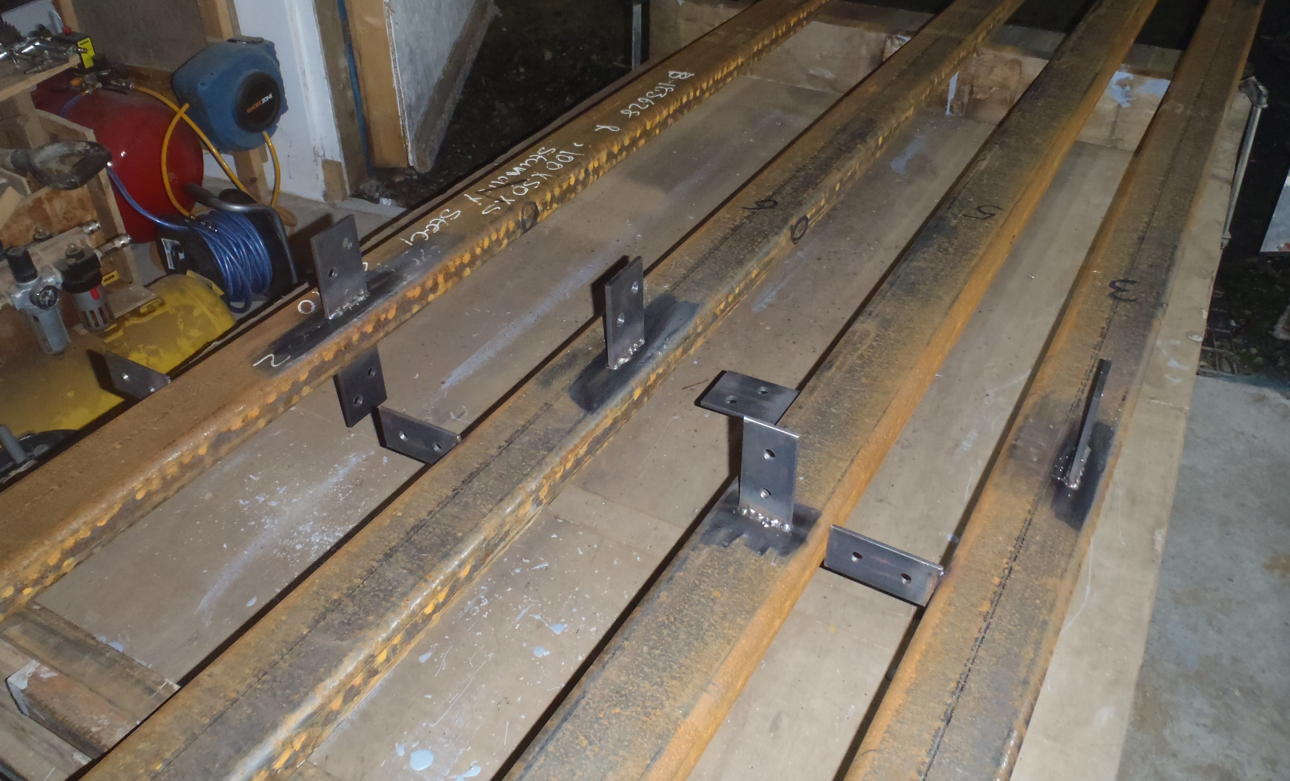
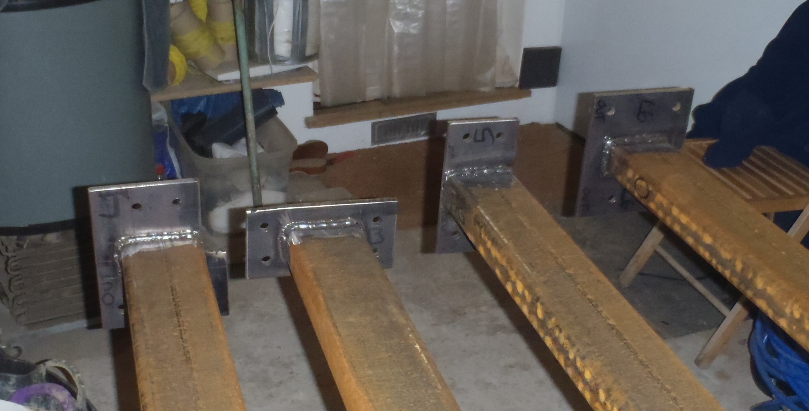
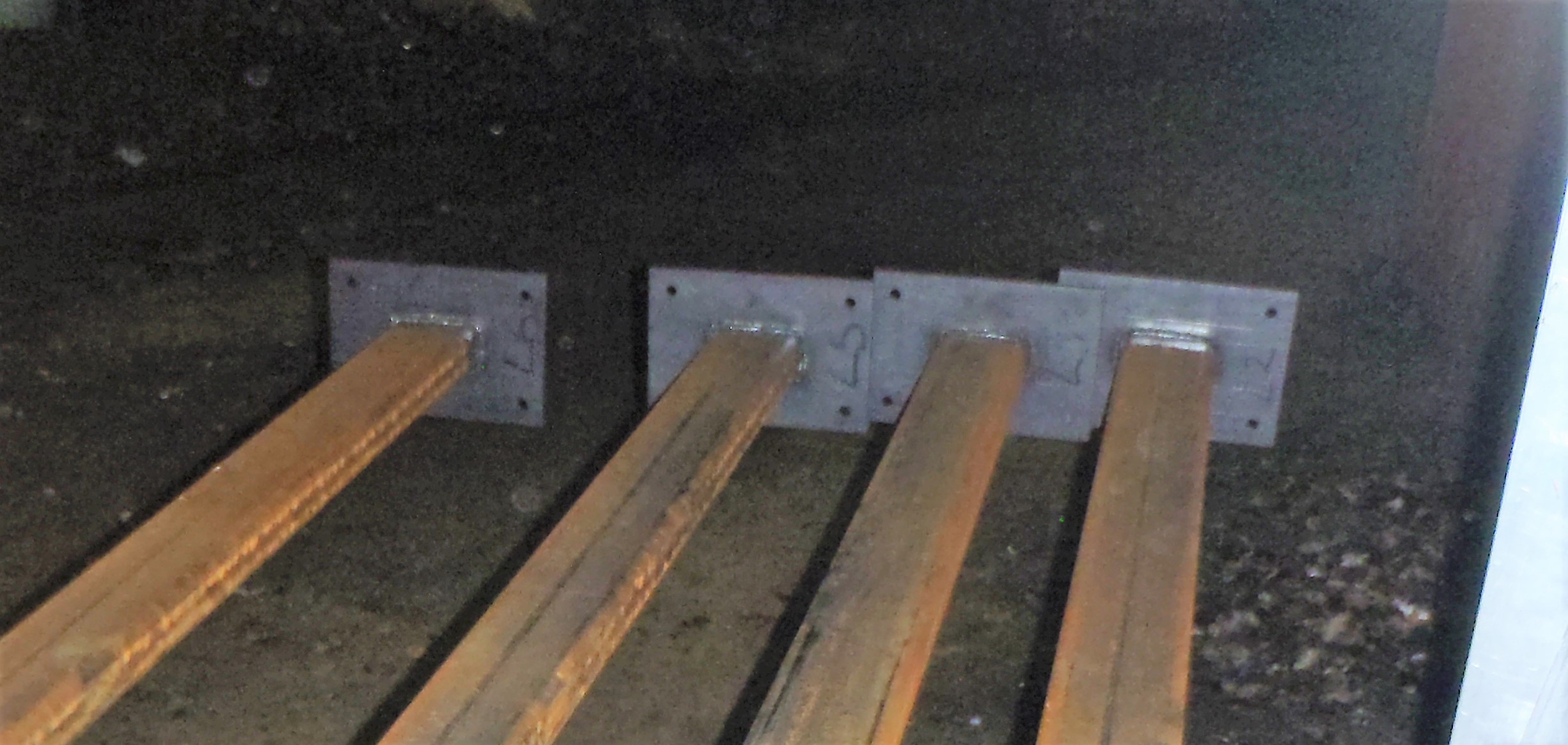
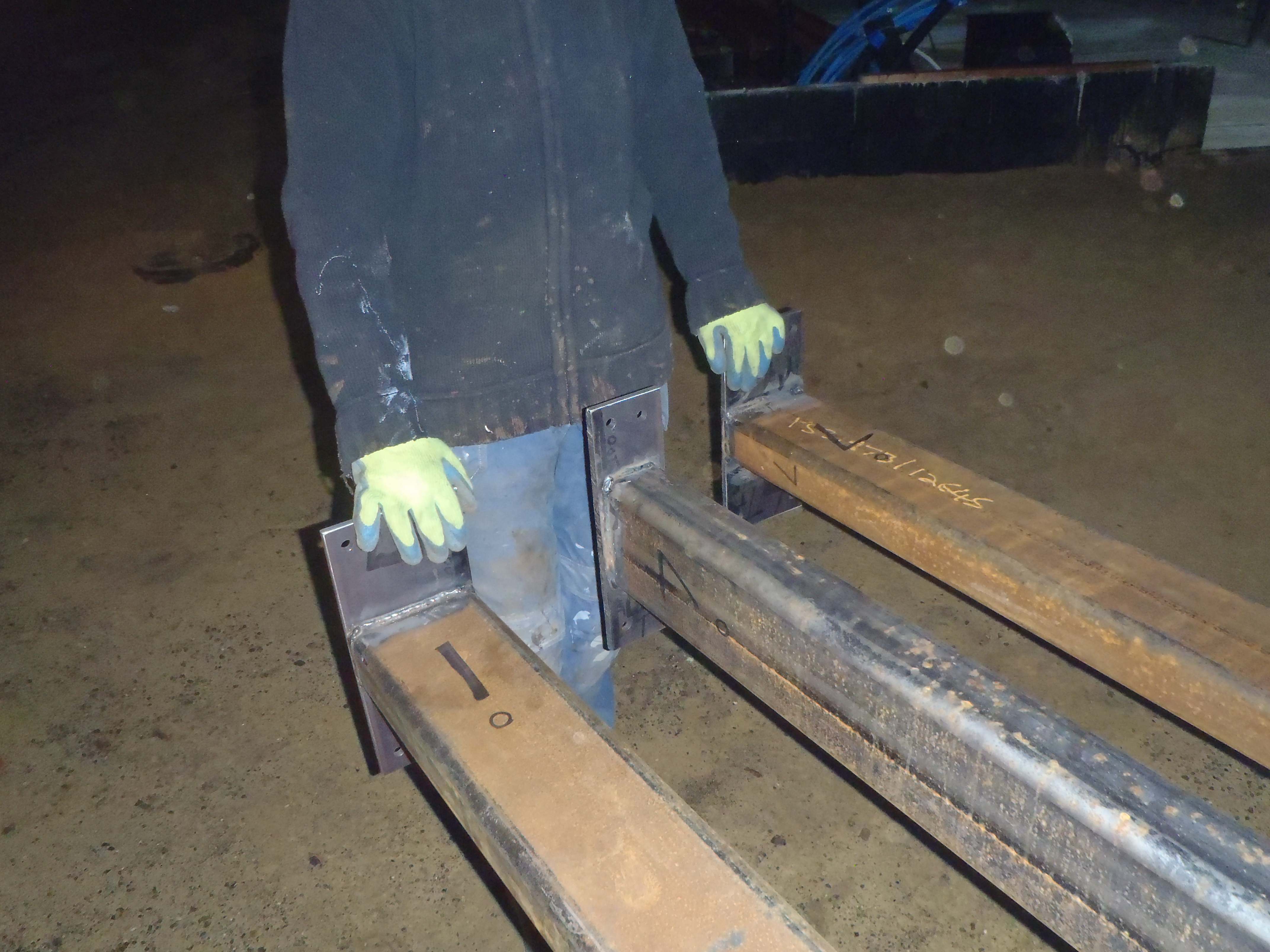
We prepared for this operation by making two bracing beams using a couple of 63mm CLS timber pieces with metal strips screwed on each end to provide the anchorage. These bracing beams are only temporary to hold this leg in place while we make further precise measurements to each and every leg before we bolt them all down into the concrete.
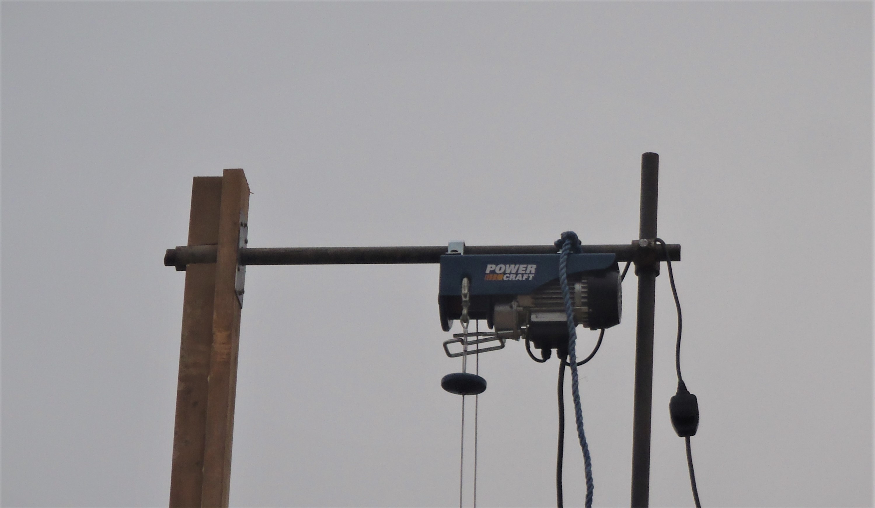
This final leg is our third heavy duty version (weighing 160kg) and it all went just fine with no signs of tension or trouble with our repaired crane wooden leg.
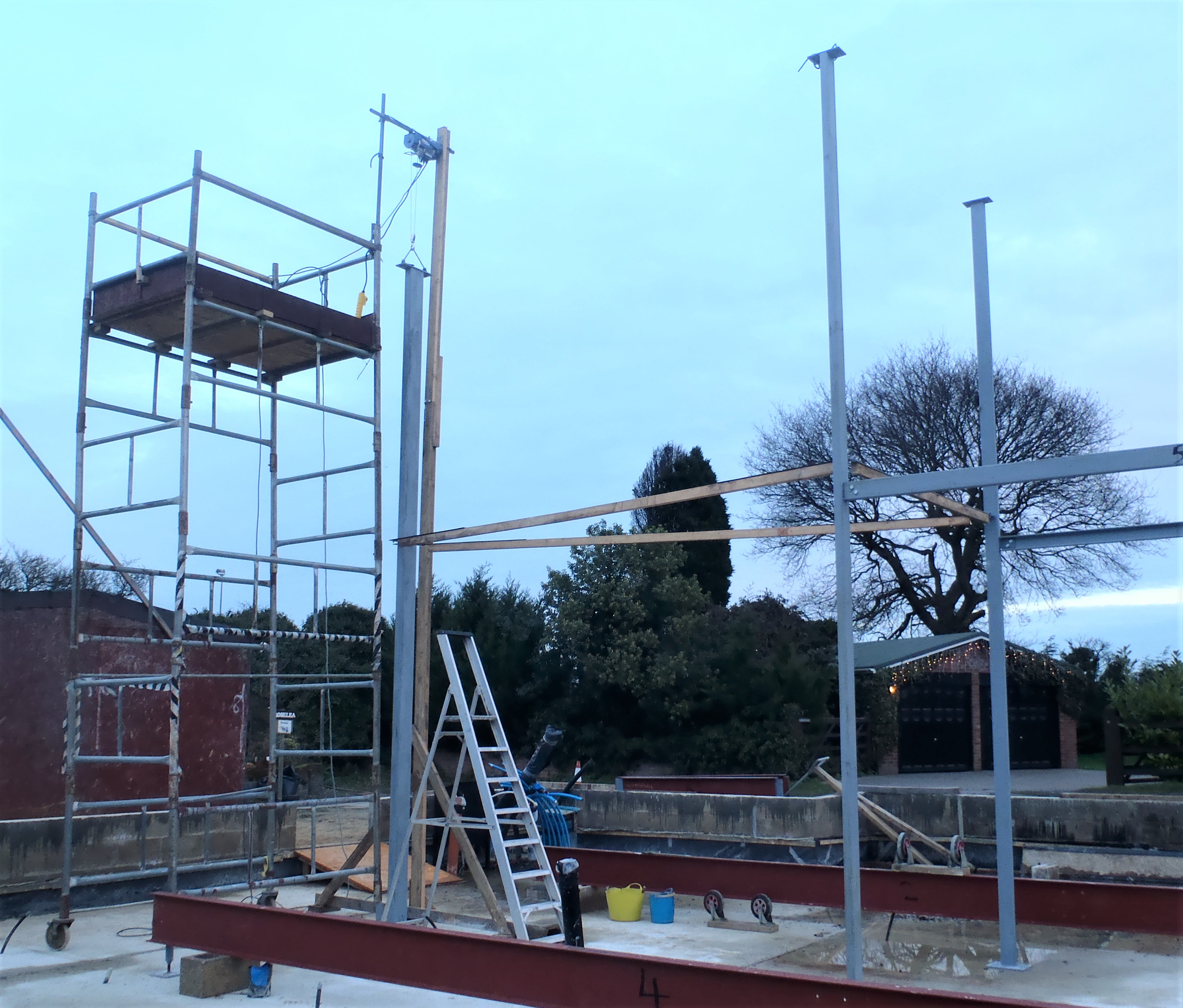
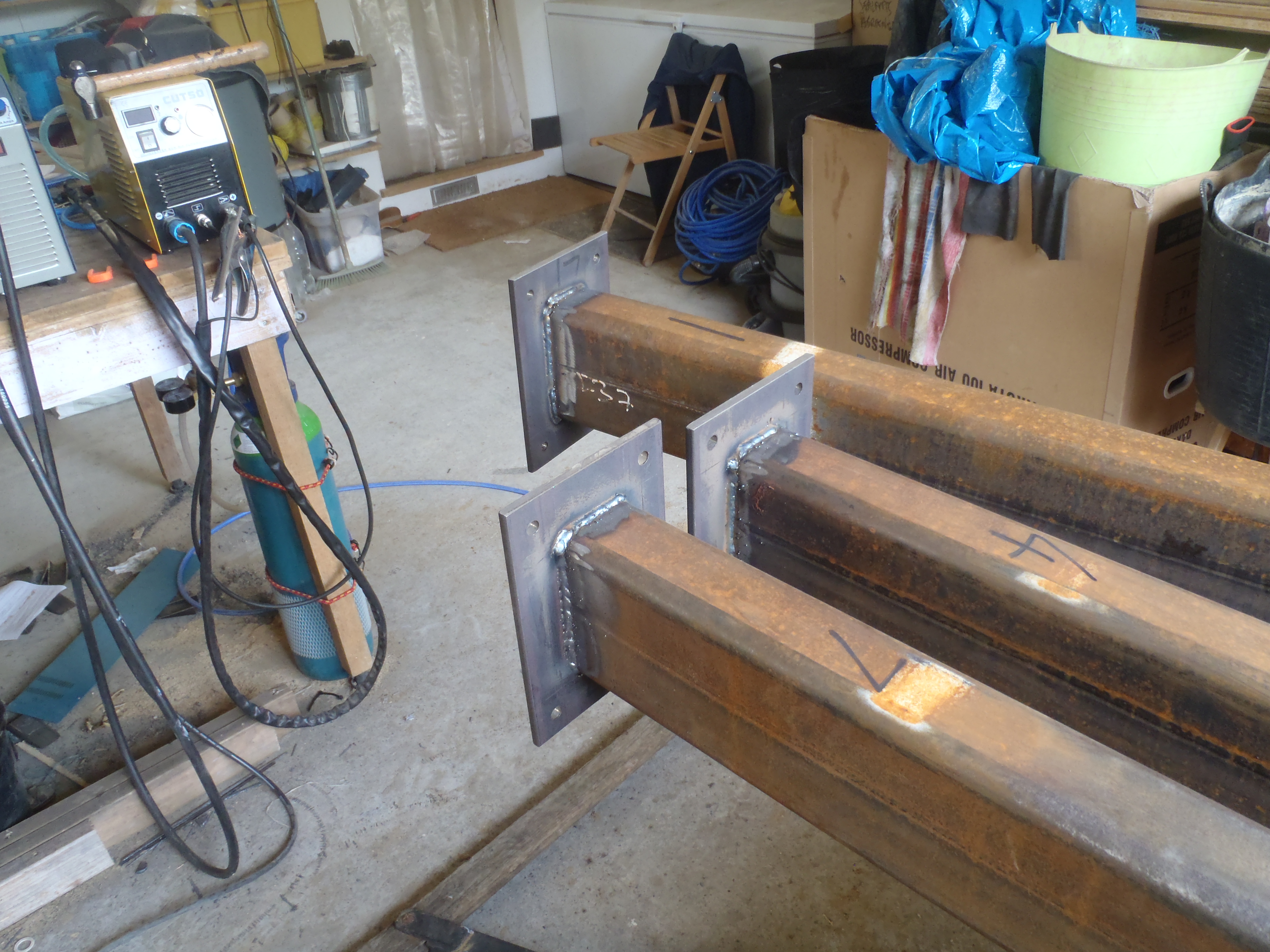
Leg-7-in-place
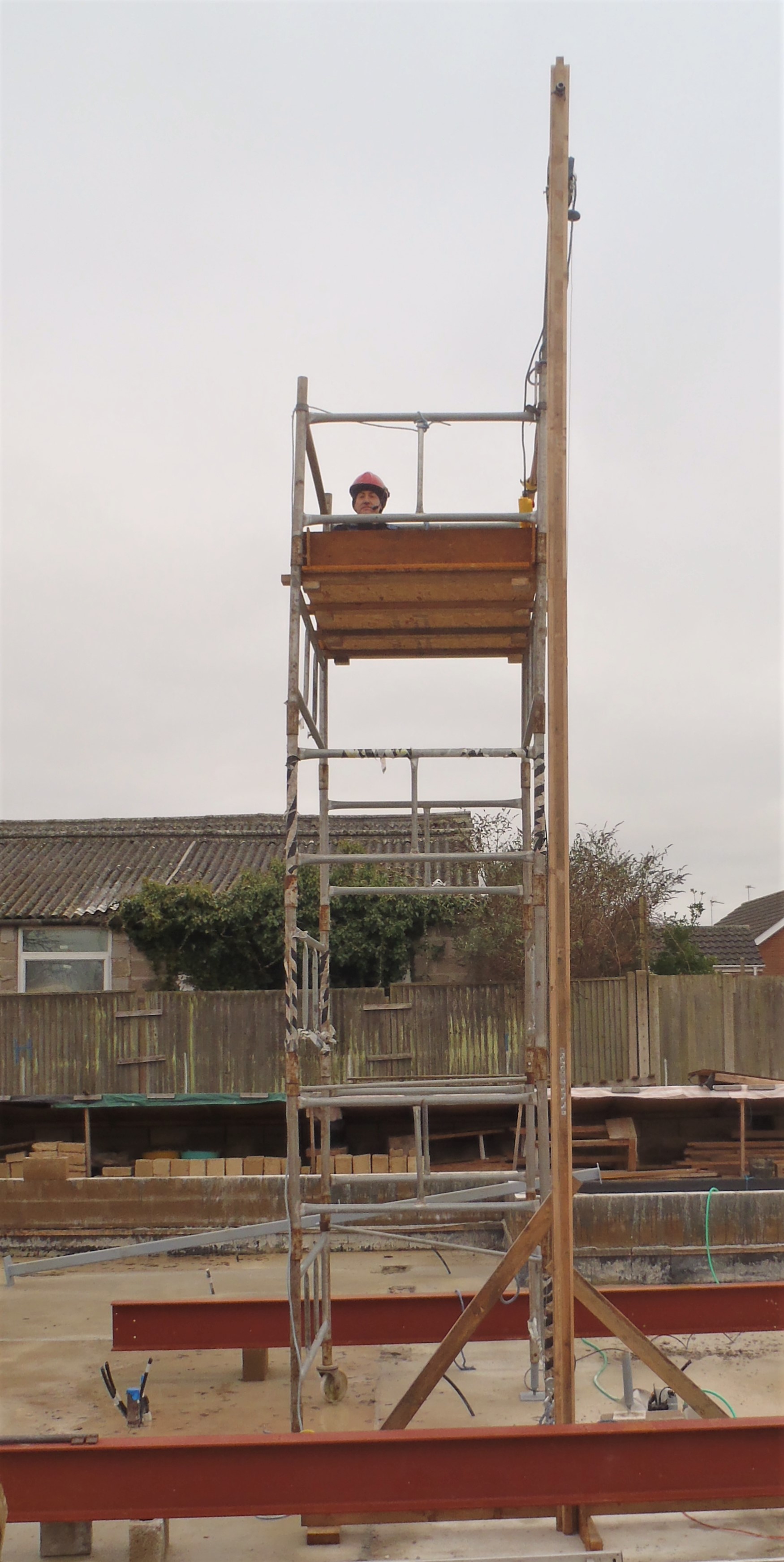
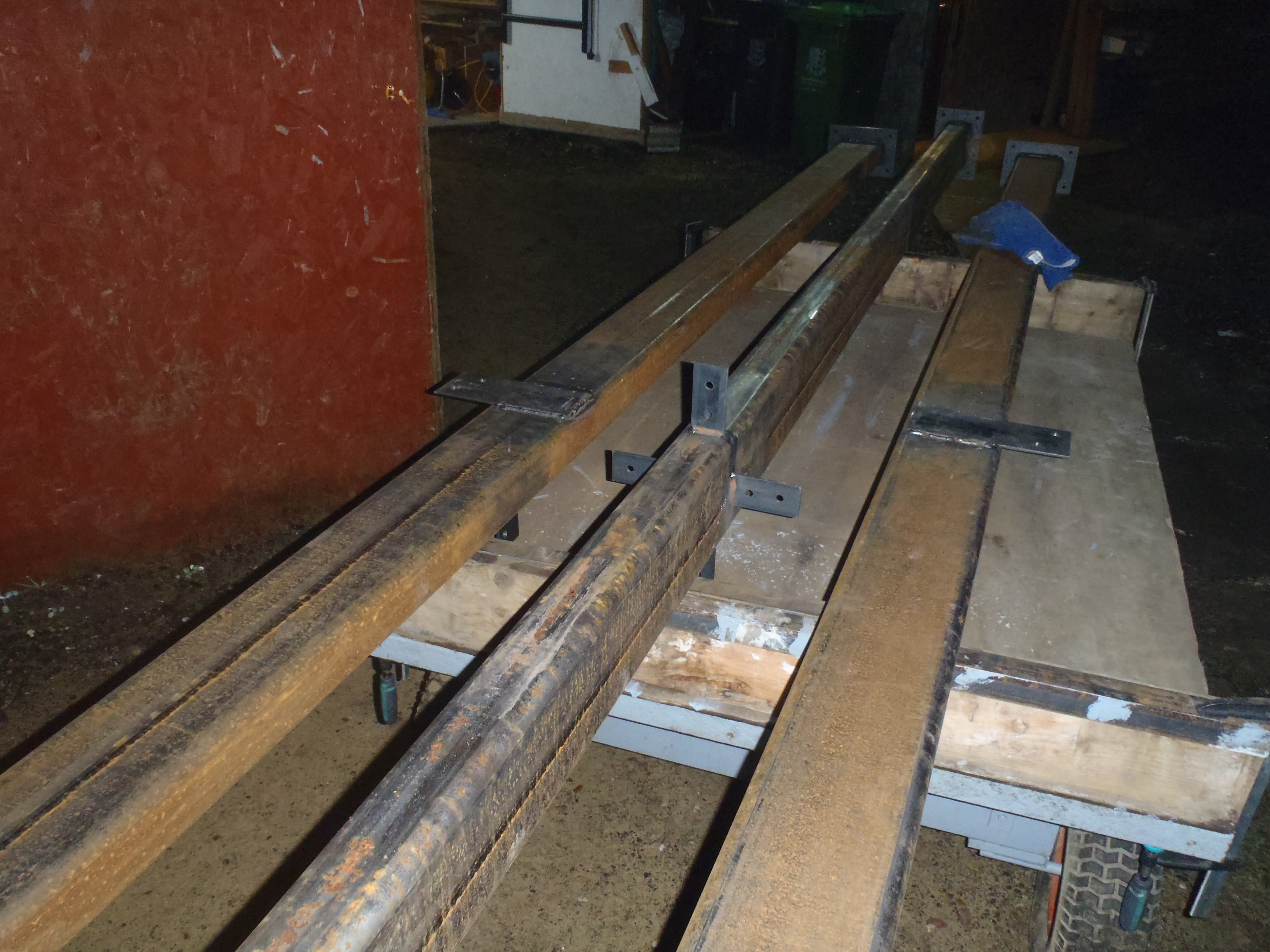
We verified the position of the previous pair of legs (number 3 and 5) to make sure they were in the correct location (only needing a slight adjustment) and then we were able to put on our bracing beams from those legs to our final leg to secure it and hold it stable. But we were concerned with a potential mishap if we had any strong winds and it may have caused a possibility of pushing this leg (number 4 it is) over sideways so we tied two lengths of rope and anchored back to the concrete wall (just like tying down a tent with guy ropes).
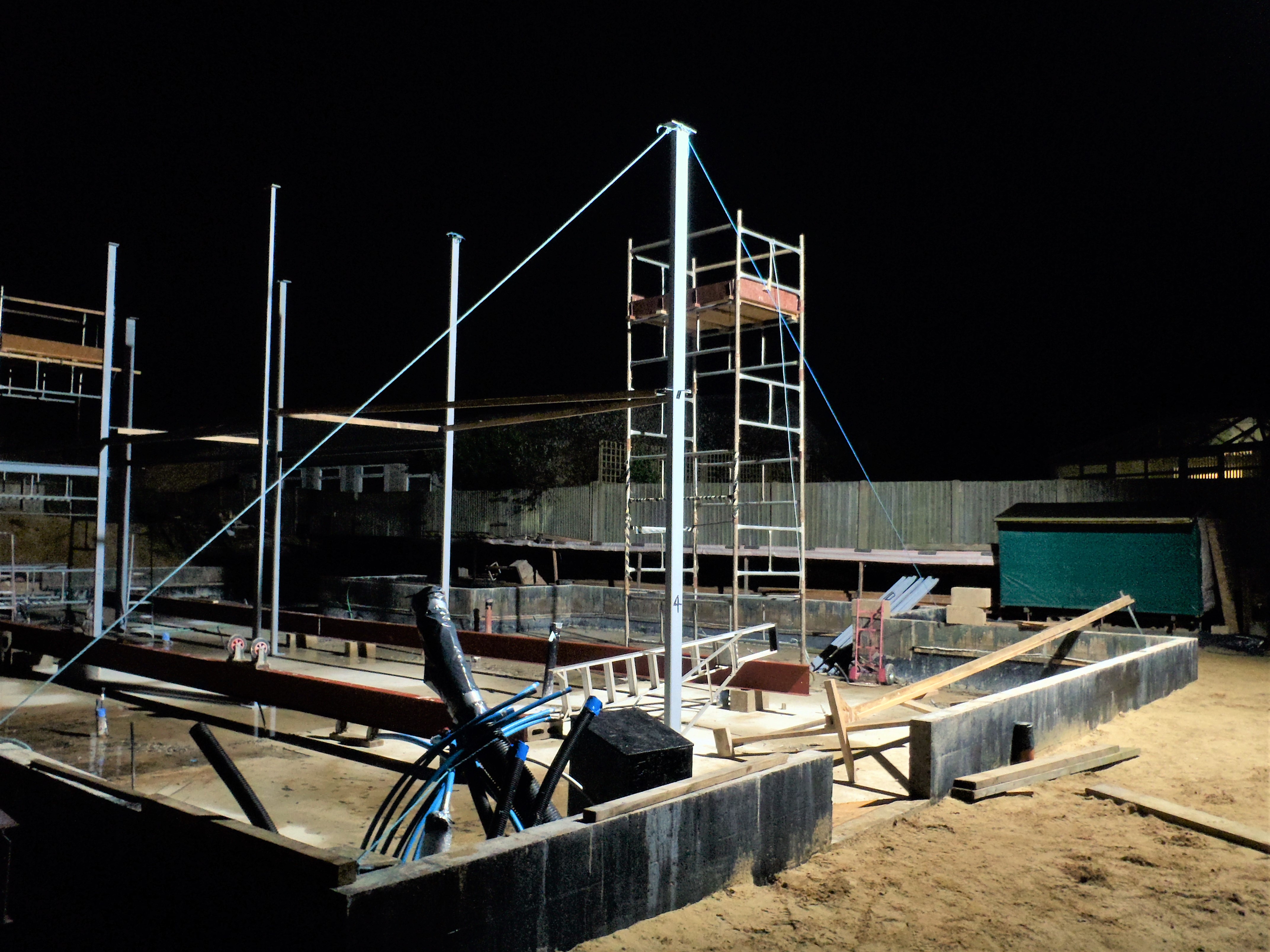
Leg-7-with-guy-ropes
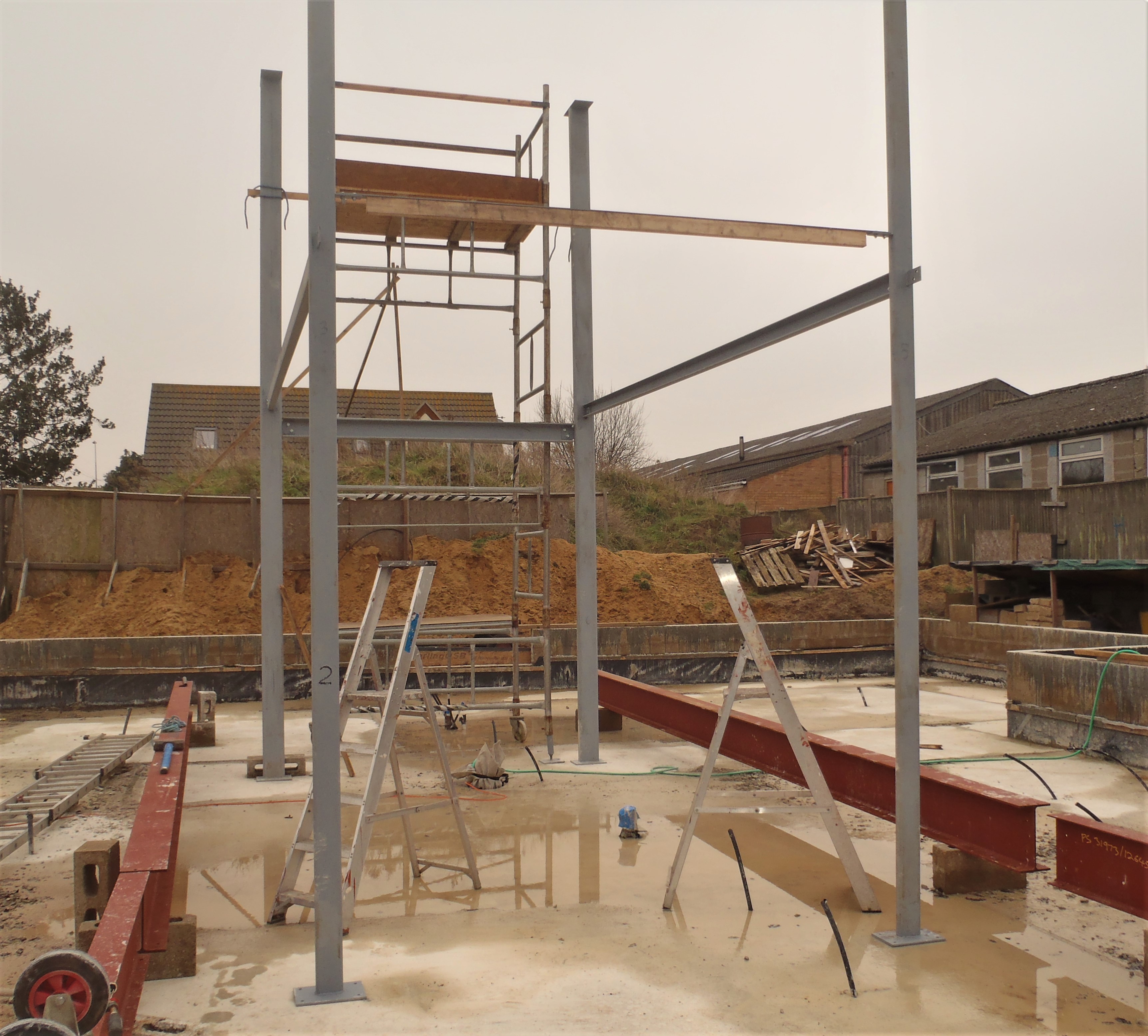
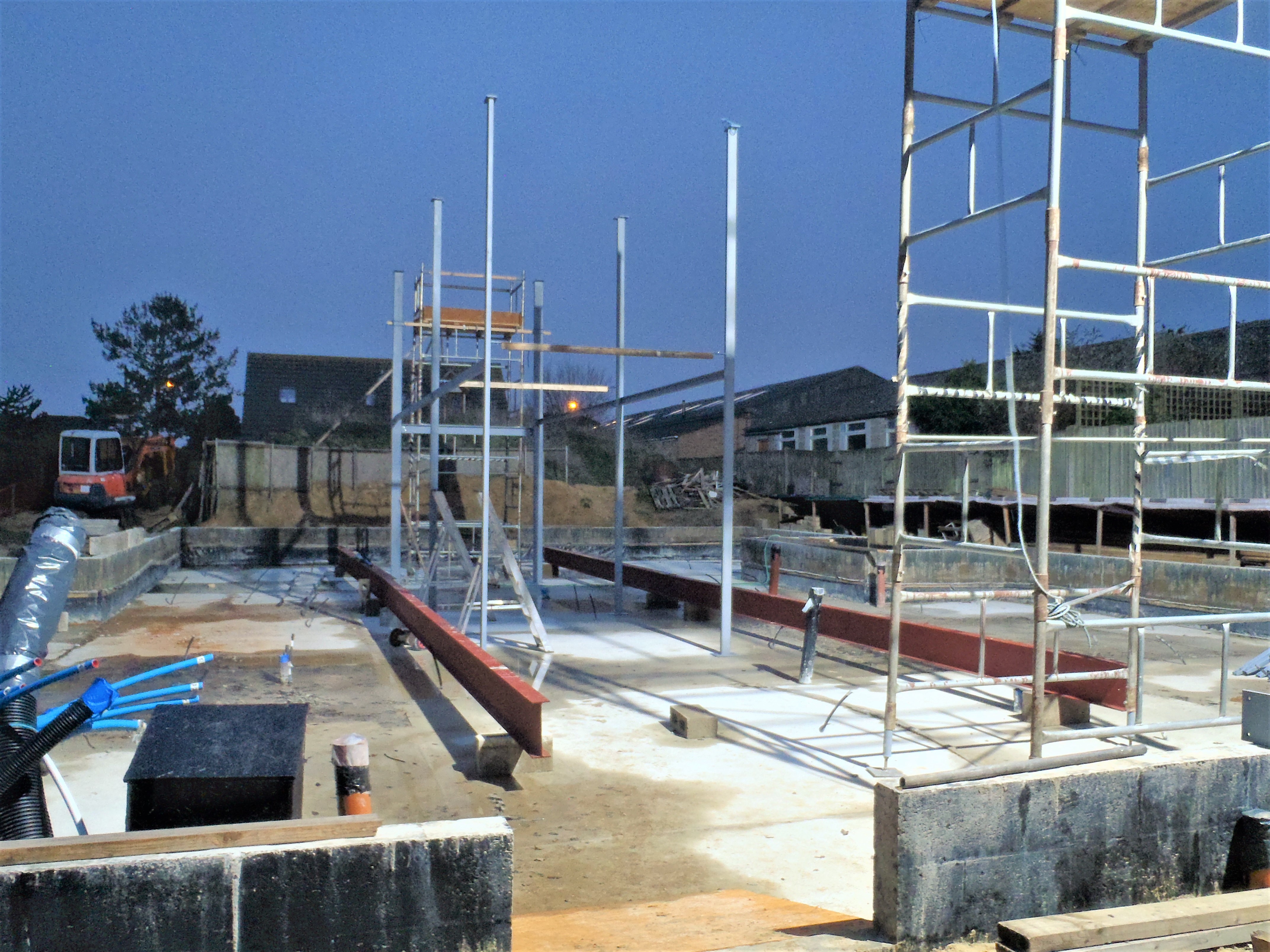
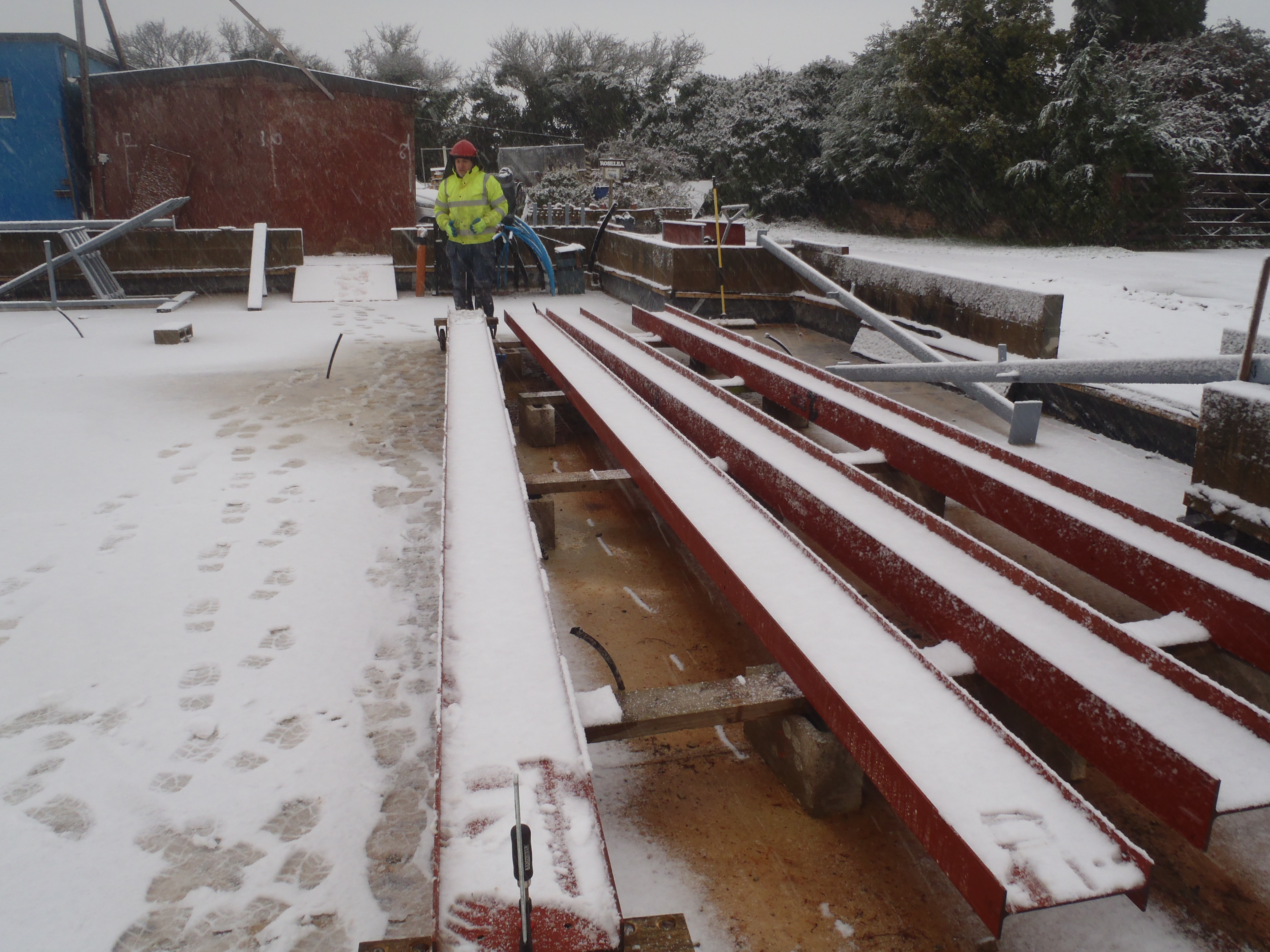
We then went back to the first pair of legs to start the exact process of measuring distances and angles to confirm the positions of the legs against the drawings. We used a laser beam to project right across from the Kitchen front wall, skimming pass the two steel legs and reaching the other side of the Great Room. We then measured from each corner of the Great Room to the laser beam and both were very, very similar (5564mm) and the gap between the laser beam to the side wall of the extension was 40 to 50mm which conforms very closely to the plans – phew thank goodness for that!
We then made sure that the distance between the legs (number 1 and number 7) were the same at the bottom and at the steel lintel (measuring 2327mm) which is within 1mm of the precise number off of the drawings.
But we were concerned about the verticality nature and our digital spirit level was saying 89.85° for these legs and we wanted to make sure that both were 90°. For every 0.05° out, then there would be an offset of almost 5mm (precisely 4.8mm) at the top compared with the bottom, therefore that 89.85° value would indicate that the top of the leg would be over 14mm further apart compared with it’s neighbouring leg and our steel cross struts wouldn’t connect together and allow our bolts to go into the holes!!
After some discussion, we came up with the idea of clamping pieces of timber between the legs at the top at the exact distances so that we can be reassured that the bolt holes will line up with the I beams and the cross struts when they get hoisted into place.
All this careful considerations was needed because we want to drill the mounting holes into the concrete to bolt down the foot plates of our legs and have them much more secure and stable before we haul up the very heavy I beams on top of them! But of course, if we bolt down the legs and then find that the tops are NOT in the correct positions and we couldn’t line up the bolt holes and locked the pieces together .. we would be rather annoyed! Hence why the deep thinking and discussion session we had to solve this problem. We will implement our solution on Monday – Phew!