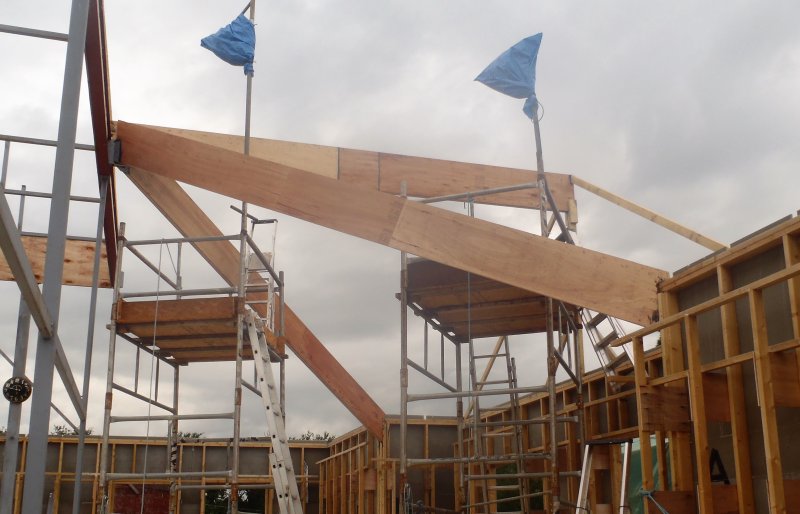
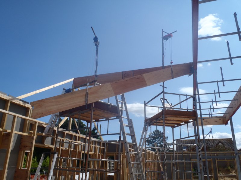
Today, we continued with preparing the LVL timber flanges for the first of the main corners of the roof, over the Great Room, in the corner where the P wall meets wall A, hence we called this rafter the PA Hip Rafter.
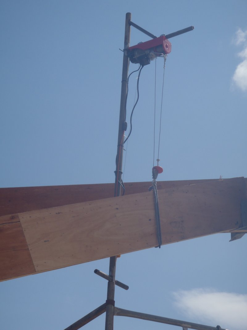
We wanted to be very careful while cutting and slicing out the Bird’s Mouth notch, making sure the length of the top flange is as exact as possible, as because we have One and ONLY ONE of these LVL special timber so making any mistakes would mean buying another one (£40 and weeks of delay)!! We achieved the accuracy requirement, double checking and analysis of how the real world reflects against our computer drawings, by the help of another little template that plugged into the metal bracket up on the steel I-Beam. We could see where we had to remove sections of the webbing so it could hook over and get past the sticking out flanges of the steel I-Beam itself. We recognised that the corner point of the I-Beam needed to be sliced off too (about 15mm using a hacksaw and plenty of muscle!). Then, down on the PA corner, the cement board was sliced away to just allow the LVL 38mm wide timber to come through and also remove an angled section of the top-plate timber so that the Bird’s Mouth on the LVL timber will lock into place. So following this corner, we made another little block of wood with the correct slope sliced out on the bottom so it could sit and line up with the new cut-away section and provide exactly where the LVL timber will go.
All this preparation work allowed us to measure the exact distance along the top flange of the rafter, all the way to the Kerb’s corner up on the I-Beam. This distance turned out to be 5600mm.
This gave us a measure of confidence to commit ourselves to cutting the Bird’s Mouth and marking out the other end using this 560mm number. We wanted the LVL flange to fit neatly up against the Kerb’s corner, so it had to have an internal corner sliced out the end of the beam. We took back outside the LBL timber with the Bird’s Mouth and the markings, got it up into the corner and up onto the bracket and slid it into the template so we knew what height it should be. We double checked the markings to make sure it was looking good, so again we committed ourselves to cutting the excess wood off the end and slicing the funny inwards pointing angled groove and got it fitted just nice and tight!! Phew!
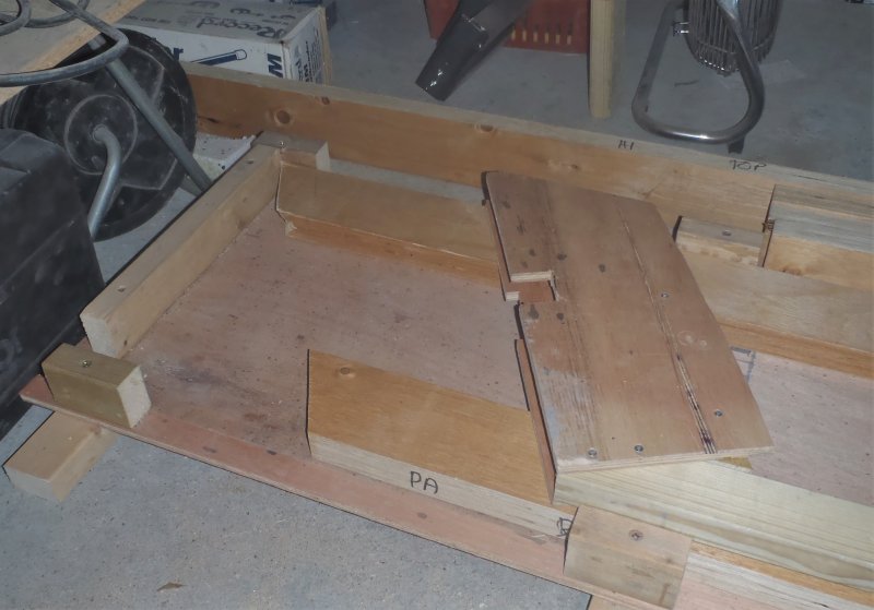
Then back to workshop with our LVL timber again, and laid it down into our rafter template so we could position the bottom flange next to the top flange (the one we have been working on) and line everything up, double checking everything again, and then slicing the bottom flange to exactly the right size too!
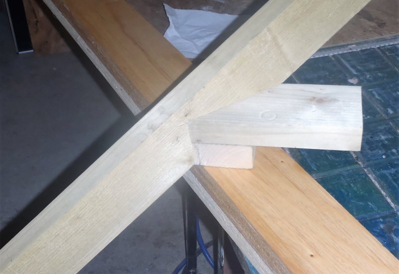
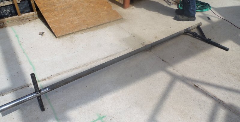
Rafter-PA-Top-end-and-Measuring-jig

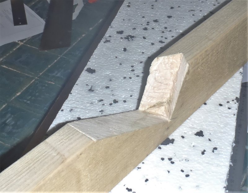
Rafter-PA-Birds-mouth
This pretty much was our day’s work – Phew! It is slow but we can’t make a mistake or it will costs us money and time and be very annoying too!! Nice and steady for these special diagonal LVL rafters around our roof. Thank goodness there are only 17 of them in total and we have done three of them so far, with the three we are working on now. Monday, we will carry on with the PA rafter and get it fitted into place and prove our methods and increase our confidence to do the other two similar Hip rafters for the other two main corners.