Blog

  • Vacuum System Almost Done

    Today, while half the work force is away at a meeting, the vacuum system was continued to be created and assembled. The various holes and boxing were created, the motor units mounted and electrically tested, and each module having rubber draught excluder stuck down around all the edges to seal the various chambers.

    Vacuum-System-Nearly-finished-1

    Vacuum-System-Nearly-finished-1

    Vacuum-System-Nearly-finished-2

    Vacuum-System-Nearly-finished-2

    Vacuum-System-Nearly-finished-3

    Vacuum-System-Nearly-finished-3


    The two boxes are now connected together, the vortex and “big” stuff collection box and the motor units and the “small” stuff collection box as you can see in the photo.
    We have hooked one motor up for a real test run and oh wow, what a suck! Grin! We went around the workshop and vacuumed lots of surfaces, large pieces, dust and wood bits and pieces and all was sucked up. Opening up the final “small” stuff collection box to inspect the filters and what was in there, and it revealed very little stuff! Just a few particles blown into the corners and a little bit on the paper filters themselves and that it! Very good indeed!! Excellent Stuff!
    So to finish off this little project, we just need to put in dampening material inside the motor unit chamber to reduce the bouncing noise and put on a lid with switches to control one or both motors, and maybe need to put a box around the vortex module as well to keep the noise down too. We will see!

  • Vacuum System Continues Construction

    While the rain came down, we went back and continued with the construction of our new workshop Vacuum system. We started building up the boxing and chambers it will need for the two separate filters and non-return flappy valves. We now have the filter box made with two attachments to hold the two paper cylinder filters, a sharing layer so that if one motor is only running, then both filters are always being used to reduce the airflow through each filter and hence reduce the speed which the filters will block up. The next layer is where the non-return valves will be situated but sofar we have just made the boxing and glued it together.
    Tomorrow, holes will be made to let the air through, both up and down, and the motors then can be fitted on top.

  • Troubles With Hauling LVL Rafter Into Place

    This morning, we sliced off the bevel wedge that needed removing off the top end of the LVL Rafter so it will slide and fit tight into the metal bracket. Then, at the other end, re removed a small section of the webbing so it can fit across the 76mm thick top plate on the walls.
    That done, we organised the scaffolding towers so that we could use our block and tackle to lift up the 60kg rafter beam without having to use the electric winch machines and instead use man power on ropes going through two pairs of 2 pulleys blocks to increase by 4 fold the lifting power.
    But, Hey Hoy, we had an incident involving a metal collar on our extending arm at the top of the tower and the fact that it snapped apart into two pieces under the twisting action and dynamic loading on the end of the extension arm.

    Broken-Connector

    Broken-Connector


    Fortunately, nothing came crashing down as it broke almost at the beginning of the lift operation and also we had tied ropes on each separate part to make sure that things didn’t slip off or come apart. Phew!
    So after lunch, we spent an hour or so to adapt our metal poles into a more solid braced design and welded everything together to avoid weak collars and bolts.
    Updated-hoist-arm

    Updated-hoist-arm


    Taking our new support lifting arms back out and set it up again, to only find that the whole vertical pole started bending over under the strain this time!! Oh Drat! Gee Wizz!
    Hoist-arm-bends

    Hoist-arm-bends

    It looked that it really needed a second leg to support the other end of the extended arm so we fetched our old wooden crane legs, reduced the height of where the horizontal pole fits through the wooden section and tried getting it to marry up and connect to our support arm. But it was leaning over drunken and we couldn’t get it to slide all the way into the metal collar!!

    Supporting-hoist-arm-with-a-leg

    Supporting-hoist-arm-with-a-leg

    At this point, it started raining so we abandoned this work and went back indoors to carry on with our vacuum unit instead. PHEW!

  • Making a Workshop Vacuum System

    This afternoon, while we waited for the glue to dry on the rafters, we carried on with the construction of a new vacuum system. It is a non-mobile system, using a vortex separator and twin motors to provide the suction power.
    The first larger chamber has been made using the vortex column and this will collect all the bigger and heavier rubbish being sucked up and then a second chamber to collect everything else down to fine dust size. Today, we were building the second chamber that will have two cylindrical paper filters, two suction motors and a box to collect the smaller particles of rubbish.

    Partially-made-vacuum-system

    Partially-made-vacuum-system


    We will carry on when we have another loose moment in our work schedule to finish it off later in the week and install it into our saw table. We will also buy new quality extension pipes so we can clean the rest of the workshop too.

  • LVL Rafters AB and DE Are Now Constructed

    Today, we assembled the two LVL diagonal Rafters in our template and glued and nailed it all together. These particular rafters are just under 6metres long and they weigh 60 Kg each – phew!

    Ready-for-second-plywood-web

    Ready-for-second-plywood-web

    Glue-Spread-

    Glue-Spread-

    Valley-Beams-AB-and-DE-Finished

    Valley-Beams-AB-and-DE-Finished


    We are waiting for the glue to dry before we do the final slice off the top end where it needs a bevel sliced off the corner so it will slide diagonally into the metal bracket to marry up tight against the C Ridge beam already up there. After that, it is a case of carrying them outside and hauling them up into place, but this time, we will use a four-way pulley system to allow us more control over lifting up the very long rafter and it can be held in place with ordinary rope while we check the ends and position to make sure it fits in well! Wish Us Luck! Grin!

  • The Diagonal LVL Rafters Are Slowly Coming

    We have been working on sorting out the design and calculations of the first set of LVL diagonal Rafters, namely, the two rafters that comes from the C Ridge, down to the corners of where the Front Extension starts. It is the first time we have tackled this type of diagonal Rafter and it is quite complicated with different angles coming into play from different directions. It is a case of making sure that we understand exactly what is going on and how the real world measurements we got, fit with the drawings on the computer and making adjustments etc.
    Finally, today we have got to the point of having a pile of parts (polystyrene foam strips, plywood webbings, internal noggings and the LVL timber) all ready and prepared for assembling tomorrow. Everything is carefully being sanded and cleaned for maximum strength as these diagonal Rafters are going to be expected to be handling quite large loads, rather than the more normal straight rafters that just goes from top to bottom!
    The whole LVL rafters, including the corner Posts that we built several months ago, will be glued and nailed together and fit nice and tight – We Hope!

  • C Ridge Installed

    Today, it was the task of taking out our C Ridge beam out and installing it into place. But first, we had to cut away some little bits of wood at the end of the beam that goes next to the steel I-Beam (to clear the sticking out flanges of the I-Beam), and also insert some filler wood pieces so that the fixing nails in the side of the metal bracket will be securely and bite into solid wood.
    Next, we weighed the whole beam on our scales and it came in at 61kg which is a fair weight but we could handle it fairly easily to take it outside and lay it down ready for hoisting up our scaffolding towers. First, we tried hauling on rope by our own muscle power but it proved rather difficult to lift and keep the beam in control, meaning not letting it fall back down again!
    We then switched over to our old method of using our mains powered winches on our existing metal poles jammed into the corner of the scaffolding tower and hoisted the beam up nice and easy. We managed to swing the beam around and have it resting across our two towers.

    Here we found that it was tricky lifting each end up by ourselves into the bracket and onto the post (on the C wall) so we ended up taking turns to be both at one end at t a time and help lift it in place. We did some slight removal of wooden material at the I-Beam end so it would fit into the metal bracket and sit more firmly back to the Kerb etc. and then we applied lots of silicone glue to the whole bracket surfaces and wooden ends to slide the beam into it final position. We then applied more glue at the other end on the post and fixed two side bracing supports to lock everything together including six fat nails in the sides of the metal bracket to anchor the beam firmly in place.

    C-Ridge-in-place

    C-Ridge-in-place

    C-Ridge-in-Metal-Bracket

    C-Ridge-in-Metal-Bracket


    Next we made two diagonal struts that fitted from each corner of the C wall and up to the C Ridge to provide both more anchorage and a surface to nail up the cement panels to form the whole gable wall over the front door and window of the entertainment room.
    C-Ridge-Wall-end-with-Bracing

    C-Ridge-Wall-end-with-Bracing


    Finally to finish off the day, we measured the diagonal LVL rafters that comes down from the C Ridge at the I-Beam end to the inner corners where the Front extension meets the main wall line. They came out at 5990 mm for the AB corner and 5950 mm for the DE corner which is pretty close to the numbers from our drawings!! So on Saturday, we will make two more LVL beams and slowly build up the skeleton of our roof!!

  • C Ridge Beam All Made Up!

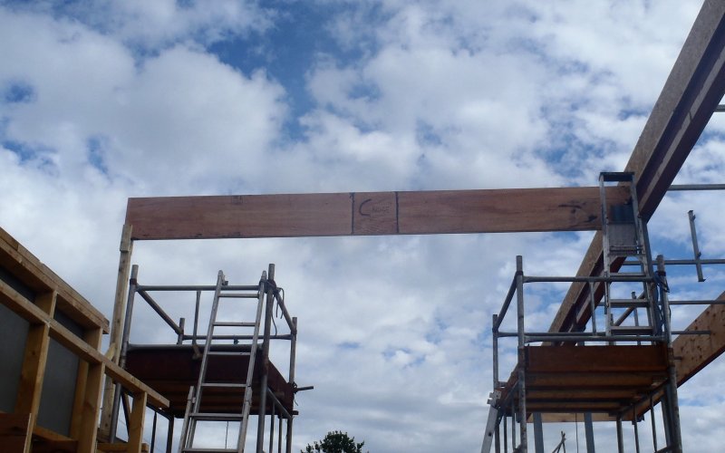
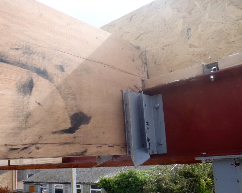
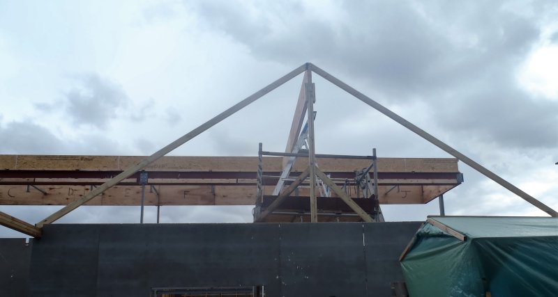
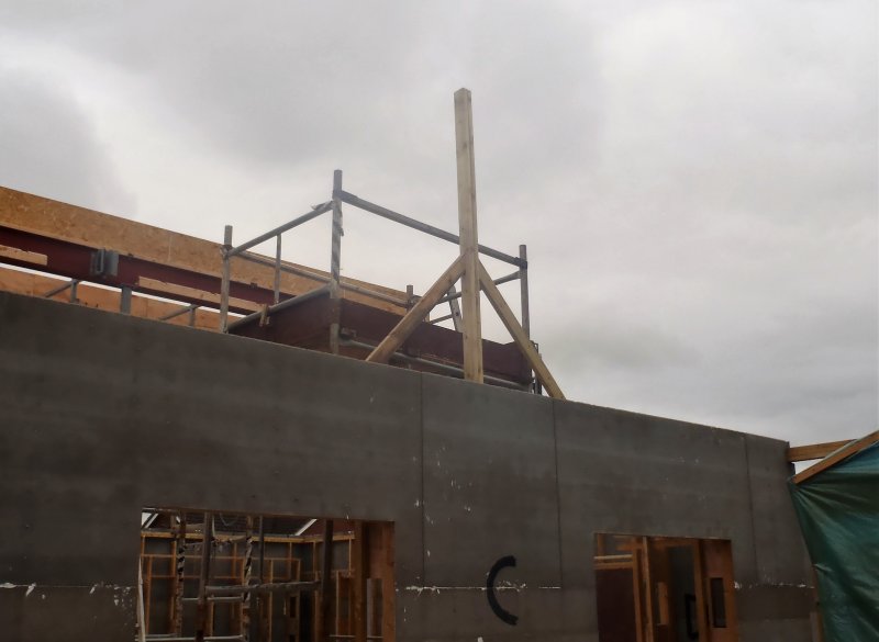
    Today, we resumed the work on creating the first Roof Element, namely the C Ridge beam that goes from the Steel I-Beam (the Skylight) to the Front Door wall, labelled “C”.
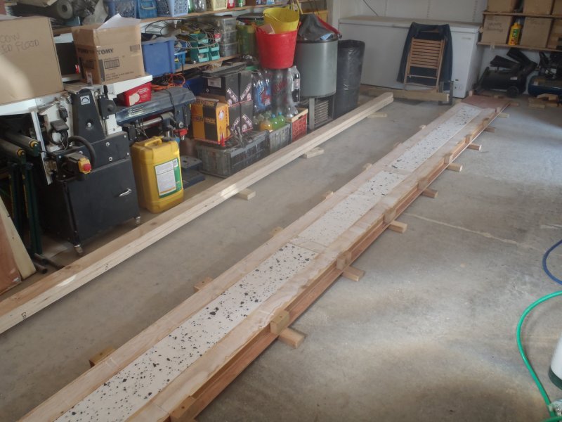
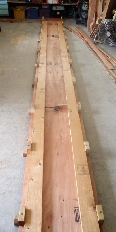
    We sanded the plywood webbing like we did for the LVL timber, again to make sure that we are getting the best condition surfaces for the gluing. We then assembled the two LVL timber lengths in the template and put in a couple of little spreaders to ensure that these timber pieces are pushed outwards and not jump around when we start nailing things together. Next we vacuumed all the surfaces to clear away the last of any bits and dust to stop them interfering with the glue joint. Here we then apply the glue using our compressed air glue bottle but first we had to fill it up, sort out the compressed air hoses, and nail gun as well so everything was ready to go!
    After the glue was applied, we took the plywood strips and placed them on top of the LVL timber in the template and then went along down each side, using our fabulous squeezer to ensure the glue joint is as tight as possible, and nailed it together to keep it nice and tight!!
    We turned it over and glued the second side but when we were about to place our plywood strips, we suddenly remembered that we haven’t put in the noggings and polystyrene foam filling!! Eek! So we spent fifteen minutes scraping the glue off again and washing the surfaces clean!! Oops!
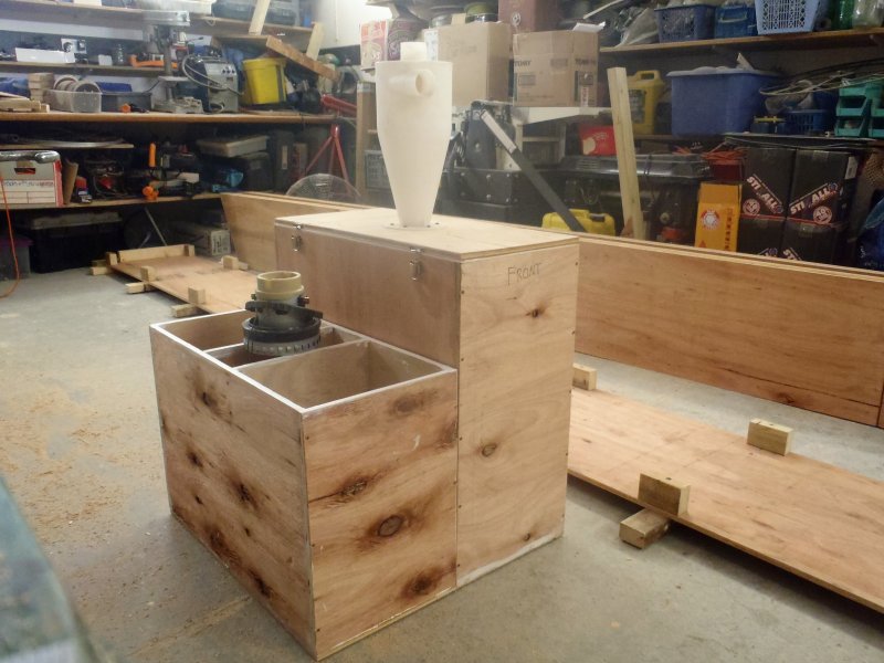
    After lunch, we set the polystyrene foam slicing machine up and decided that it would make sense to get and install on a fourth hot wire near the top of the machine so we can slice the required width of foam without having to adjust the 3 wires which slice the foam into 38mm sheets which is what we need to fill in the space inside the box beams we are making. That took a little time to sort out as well.
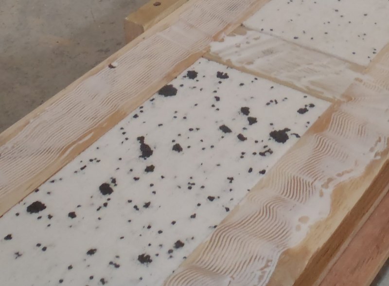
    Finally, we sliced up one whole sheet of the polystyrene foam board into 3 strips of 260mm wide pieces and then sliced these 3 pieces into a further 3 thinner pieces to make 9 in total of 260mm by 38mm thick by 2400mm long strips, we only need little over 2 strips today. The remainders will be used later on inside other beams.
    Then we chopped up four pieces of 89mm CLS timber and shaved tiny slivers off them so they fit in between the top and bottom flange, one at the two ends, and two over the joints of the plywood webbing. After that, we inserted in the thin foam strips to fill in all the empty space and it went in quite nicely if we are allowed to say so!!
    We then sanded and vacuumed the second set of the plywood strips and vacuum all the template, the LVL timber and foam and make sure it was all clean again, ready for more gluing.
    We then put on the second layer of plywood strips, this time it was ok to do so! We went along again with our squeezer machine and while squashed tightly together, it was nailed tight, all the way along both edges, just like last time.
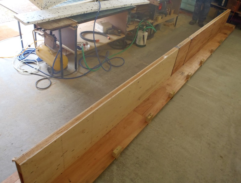
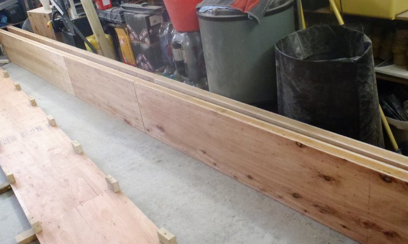
    Ridge-Beam-C-Made

    Ridge-Beam-C-Made


    That concludes the creation of one Ridge Beam – Phew!
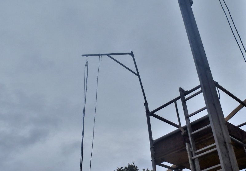
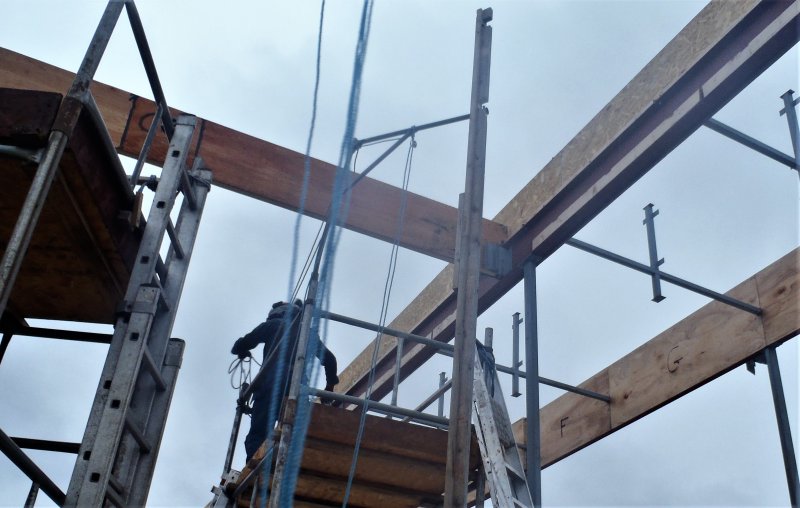
    We pulled it out of our template and placed it to one side on little blocks to allow it to dry without sticking to anything important like our template! Tomorrow, we will go outside and install it up for real and actually have in place the very first element of our roof – At Last!! Grin!
    Today, it was slow and fiddly, but we were learning our ways and means of doing this job so we should get quicker and be able to make the next beams more quickly. The next ones planned is the two diagonal rafter “valley” beams going from the same point up on the steel I-Beam where the C Ridge is and down to the corners to the left and right sides of the front door and Entertainment Room where the walls meets the main house front walls.

  • Measuring for Real and Building Gable Wall Over Front Door Wall

    Today, we took our Laser level measuring equipment and did some Reality measurements. We wanted to see what things were in the real world, rather than what’s on the drawing in the computer!
    We did the following:

    • C wall height : 2990 mm above ground (3000 mm on drawing)
    • Metal Bracket for C Ridge : 5040 mm (5039 mm on drawing)
    • Length of C Ridge : 5347 to back of metal bracket (5348mm on drawing)

    The last measurement we tried to do by propping up a straight 89mm CLS timber flat against the C wall and projecting upwards to get to the height of the C Ridge beam but we found that it was still too wobbly right up there.
    So we decided to build the first part of the framework on the C wall that will form the gable end and hold up the C ridge beam itself.

    C-Ridge-end-support

    C-Ridge-end-support


    Combining to 89mm CLS pieces together to form a single solid post and two diagonal struts to anchor it in place. At this point, we could accuracy measure the distance from the front of the C wall and back to the metal bracket up on the steel I-Beam.

    We also reassembled the second scaffold tower to give use a working platform at both ends of the ridge.

    Finally, to finish off the day, we sliced up 3 sheets of plywood into six strips of 477mm wide and cut the two LVL timber pieces down to 5347mm and 5350mm (the second one is for the top flange that goes slightly further back to the Kerb of the Skylight. We sanded the surfaces of the LVL timber to remove any dirt and roughness to make a smooth and clean surface for the best gluing joints.
    Tomorrow, we will carry on with making the C Ridge beam in our huge template and then install the beam up into place to form the very first structural element of our Roof!!

  • Created Rafter Template and Jig Unit

    Today, we set out to build the enormous template that will hold all the pieces that makes up a rafter element. The longest rafter we have to manufacture is 6.1metres long! So we took 2 sheet of our regular 12mm thick plywood and cut 3 strips of each being 476mm wide. Then we chopped up 12 CLS timber pieces each measuring 590mm long to provide the footings under the plywood and also joiners to connect the 3 strips together. Then, we again chopped up some further 26 pieces of CLS timber but this time being 100mm long. These had a 6mm hole drilled down through the wider direction and with a 100mm long screws, were fixed down on the edges of the plywood at the same position of the footings. These smaller items provides constraint to brace and hold the flanges in place when we assemble the each rafter in turn.
    There was a special requirement to cater for, for the LVL diagonal rafters and ridge beams, where all 17 of this type, comes in a variety of sizes, but most importantly, about 5 different heights. This means that we had to have some means of extending the width of the template and we did this by cutting a further 9 strips of the plywood, a set of 23mm wide, a set of 33mm and finally a set of 76mm wide strips which we can place alongside the main plywood base board and extend the overall width by a combination of different width by using one or two strips together and screw the second constraints in place to lock the whole lot tight.

    Rafter-Jig-Portrait

    Rafter-Jig-Portrait

    Rafter-Jig-Widescreen

    Rafter-Jig-Widescreen


    It only just fitted on the floor of our workshop, the total length of our template is 6.6metres long! Phew!
    We stopped slightly early to go back to the computer to make a definite and final list of the LVL rafters and ridges along with their sizes and how many plywood webbing strips we would need to build each rafter.
    Tomorrow, we will slice up some more plywood sheets to make a stock pile of prepared webbing and also the same for the polystyrene foam strips too.