Blog

  • Final Stage of Building the Ker Around Skylight Continues

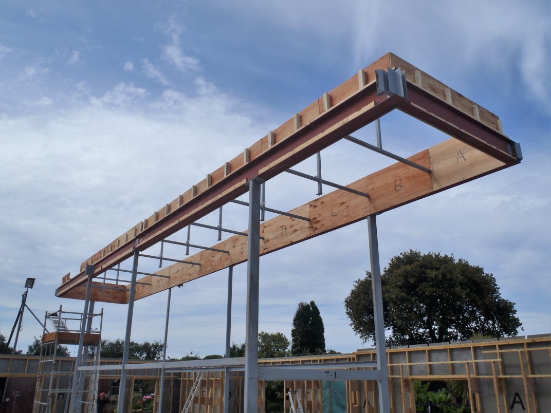
    Today, we carried on with the last stage of putting together the Kerb Framework around the Skylight. We Came along the long side of the Skylight (nearer side to the swimming lane) working from the Great Room end towards the Garage.

    One-side-of-Kerb-finished

    One-side-of-Kerb-finished


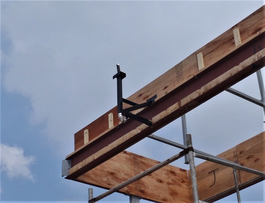
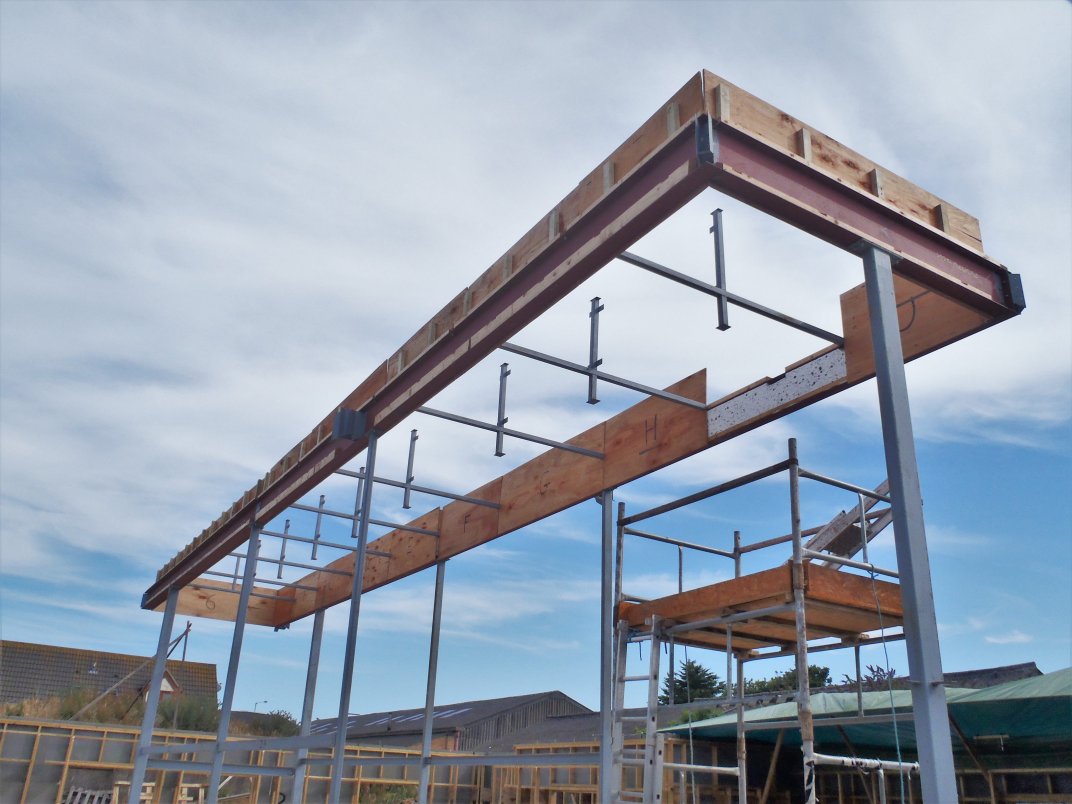
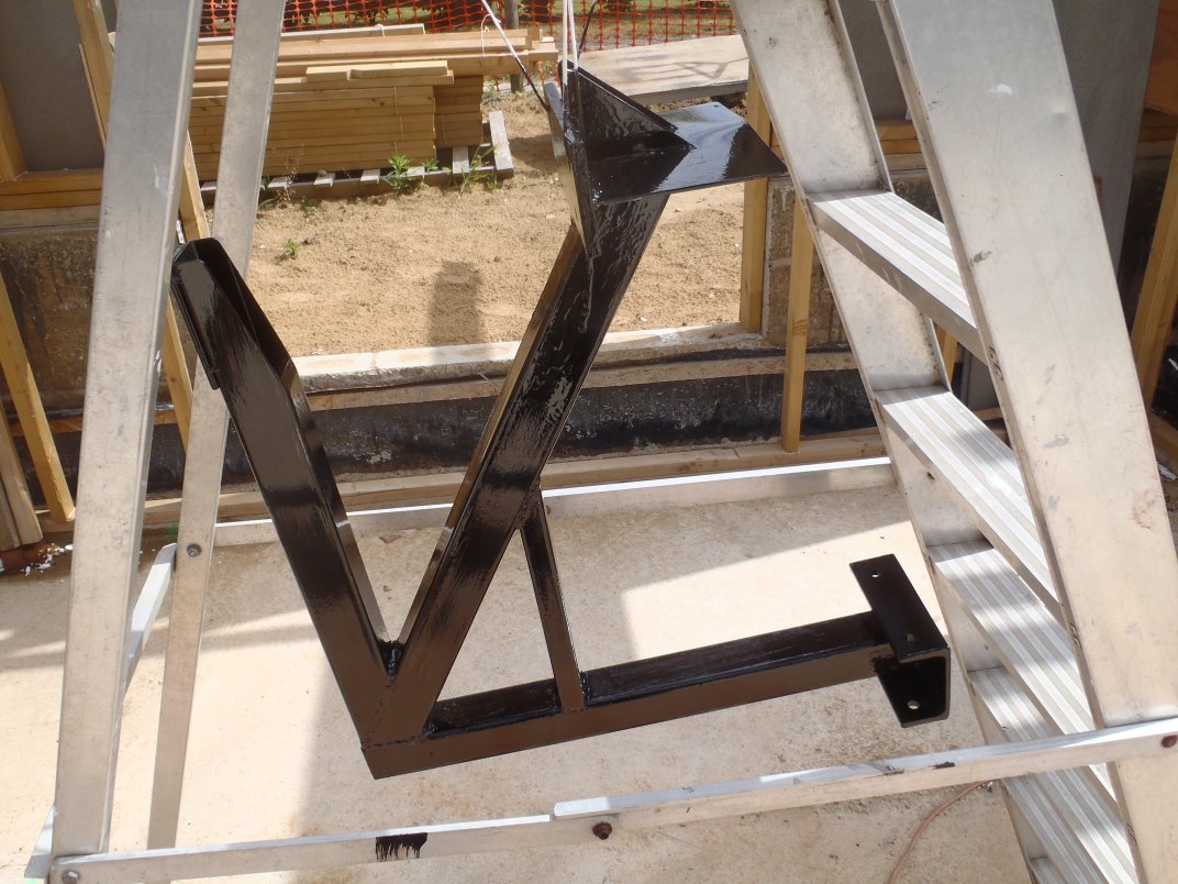
    We just about managed to get that done before lunch, stopping just short of the Chimney Support Arm. After lunch, we resume our way around and finished the day about half way along the other long side, this time the side nearer the Loke!
    Nearly-halfway-along-the-other-side

    Nearly-halfway-along-the-other-side


    All is going in ok, with the glue, screws and water protection skim on the top edges of the plywood and OSB boards. We have just about 8 metres to go and then we are finished completely. The next job is to start building the special diagonal rafters for the 12 corners and get them installed on their special wall legs and get everything positioned and fixed into place.

  • Half Day on Building Kerb Framework

    We carried on with building up the Kerb Framework around the Skylight today, finishing off putting on the top planks of timber, the 89mm CLS pieces around on the narrower sections.
    Then, after a nice interruption by some family visitors arriving coming to see our work etc, we then started putting in the final layers of the polystyrene foam boards and covering the whole lot up with the 18mm OSB boards to make a strong outer skin to the Kerb and provide a good solid structure to fix the roof rafters, the various roofing components like the copper flashing to etc.
    We completed one section down at the Great Room end of the Skylight.

    First-part-of-kerb-finished

    First-part-of-kerb-finished


    Tomorrow, we will carry on up the two long sides, inserting the 38mm thick foam boards and gluing and screwing down the 18mm OSB covers.

  • LVL Planks Sliced in Half

    This morning, we sliced up the LVL timber while we waited for the overnight rain to dry off the woodwork. The Laminated Veneer Lumber arrived as 220mm wide long planks and we needed to slice it in half down the middle to make the timber pieces we wanted.
    We set up four trestle legs to support the long lengths and use our mains powered circular saw and vacuum cleaner to stuck up the sawdust, and went through the dozen planks.

    Sawing-the-LVLs-in-Half

    Sawing-the-LVLs-in-Half


    We were on the last plank when our vacuum cleaner became blocked up and we discovered that we generated so much sawdust that it filled the cleaner right up to the rim!!

    Generates-a-lot-of-sawdust

    Generates-a-lot-of-sawdust


    We now have 34 lengths of LVL timber, all 110mm wide by various lengths from 4metres to 7metres, ready for creating the diagonal rafters that goes into the corners of the roof plus a couple of specialised ones for our back extension roof structures.

    The-sliced-up-LVLs

    The-sliced-up-LVLs

  • Polystyrene Foam Inserted and Long Top Planks Put On

    Today, we worked on the Kerb framework of the Skylight, starting early at 9am and worked until 4pm when the rain (as predicted) came in quite hard. We got a bit wet at the end there – grin!
    First of all, we cut up the thin 30mm thick polystyrene foam pieces and slid them into the gaps along the wider steel I-Beams sections as this is enclosed and can only be done before putting the timber piece on the top of the framework.

    Insulation-inserted-in-gaps

    Insulation-inserted-in-gaps


    Then, we put on the 69mm wide pieces of timber along these sections, gluing and screwing the plank down and squeezing in the plywood coverings to make it all flat and neat.
    We worked our way around the wider steel I-Beams and then carried on onto the narrower I-Beams which has a vertical timber piece as the top plate. It is a 89mm CLS timber and we managed to do one side of the steel I-Beam (on the Loke side) before the rain came.
    Top-pieces-added

    Top-pieces-added


    Tomorrow, we will carry on around the end with these 89mm CLS timber and back up the other side plus the final piece at the end over in the Great Room. After that lot, we then can put on the outer 18mm OSB boards to cover up all the framework and present a neat clean facia, ready for our roof rafters to press up against it etc.

  • Sliced Up Polystyrene Boards

    Then this afternoon, while the rain came sprinkling down, we were in the workshop slicing up lots and lots of polystyrene foam boards into narrow strips of various thickness, in order to fill up the gap inside the Kerb framework of the Skylight.
    We used up lots of old left-over pieces to make the following items:

    • 9 x 277 mm high by 38mm thick strips
    • 6 x 327 mm high by 38mm strips
    • 6 x 327 mm high by 30mm thick strips.

    All strips 2.4m long.

    Sliced-up-insulation

    Sliced-up-insulation


    We had to widen our Hot-Wire cutting machine to accommodate the wider pieces, as we had not originally envisioned making these sizes of insulation strips. That took about an hour to disassemble and reassemble the machine onto a wider base board!! But we managed to slice all what we needed before the end of the day!

    Tomorrow, we will get back out there and start putting these strips in place up on the Kerb framework, hopefully weather permitting!

  • Chimney Support Arm Is Done and Mounted

    This morning we put together the 3D printed plastic sweep bend and connected it to a length of 38mm diameter black pipe going up the middle of the chimney support arm.

    3D-Printed-Bend-on-bracket

    3D-Printed-Bend-on-bracket


    We spent yesterday designing and printing the 135 degrees bend in a tight 100mm radius curve, we had to make it in two pieces with two collars to lock it all together nice and tightly.. it took about 6 hours to print all the pieces. We also printed two little gap filler pieces to go up inside the square steel tube to block off the open ends where we could apply a squirt of silicone sealant and glue the black pipe into place and stop the rain water getting inside the pipe or steelwork.
    3D-Printed-parts-for-Chimney-conduit-bend

    3D-Printed-parts-for-Chimney-conduit-bend

    Bend-assembled-and-protected-in-foil-tape

    Bend-assembled-and-protected-in-foil-tape


    We then mounted the whole thing up on the steel I-Beam with 4 10mm bolts and then drilled a 12mm hole through the bottom flange upwards and into the support arm bracket as well and bolted that section down nice and tight too. The black pipe will eventually extend through the kerb to the inside to allow cables to be connected to the ‘chimney’.
    Chimney-bracket-installed

    Chimney-bracket-installed


    Finally, we put aluminium tape around the new 3D printed (which is made using red PLA plastic) to protect it from the harsh UV radiation from the Sun, while it is exposed to the weather. It will be eventually all covered up by the rafters and roof boards later on.
    And just before the rain arrived at 1pm, we mounted up the final plywood covering on the inner surface I-Beam to complete the covering of the full loop of the inner Skylight “hole”.

  • The Kerb Framework Gets First Collection of Timber Posts Installed

    Today, we went around with two tubs of short timber pieces, one full of simple 63mm CLS timber pieces and the other full of glued together T shaped timber pieces. We started at one end of the Skylight region up on the steel I-Beams and using our template to guide these short pieces so they end up against the plywood boards already up there. Each piece was glued, positioned where each rafter will be and also aligned vertically and then screwed onto the plywood.

    Tie-pieces-glued-in-place-1

    Tie-pieces-glued-in-place-1

    Tie-pieces-glued-in-place-2

    Tie-pieces-glued-in-place-2


    We couldn’t quite do all of them as we are still waiting for the Chimney Support Arm to be ready and installed before we can finish off that particular section of the I-Beams, and also we got to go around each corner to put some more in to help bridge and join the two edges together at each corner too, plus at the point where the steel I-Beams changes from 100mm width to 160mm width.

  • Chimney Support Arm Gets Second Coat of Black Paint

    First thing this morning, the steel Support Arm for the Chimney was painted with its second layer of the black metal weather proof paint again, outside on the step ladder.

    Chimney-Bracket-Painted

    Chimney-Bracket-Painted


    This afternoon, after we had finished our other job we had on today, we brought the metal arm, now dry, back to the workshop and looked into inserting a large bore plastic tubing (38mm diameter with 2.5mm thick walls) up the middle pole (the one that will appear above the roof surface) and put a curve in it so we can have a gentle bend to make it easier to thread wires and cables from inside the house to the chimney. But we discovered that just simply heating up the plastic pipe with a hot air gun wasn’t enough. It indeed softened the plastic but it was very difficult to make it bend in a gentle curve without buckling or distorting in funny ways. We knew we needed an interior support to hold the plastic in a round shape but we didn’t have anything to hand. We did wonder whether to use fine sand and pack the tube with it and then heat it up and bend the curve but we wondered that the hot plastic will absorb the sand particles and make it rough or more likely that the plastic being stretched to go around the bend (more than 140 degrees around) would make the plastic wall so thin that it may even break apart or be so weak to not be able to take any pushing of threading rods etc.
    So we decided that we would manufacture a specialised sweep bend on our 3D printer instead and have sockets and sealant to join all the pieces together to form the necessary path to guide our wires and cables!!

  • Alignment Template Created for Skylight

    And finally, we created a simple alignment tool to help us when we come to install the little pieces of timber for the Skylight framework module. We needed something to “transfer” the position of the slots in the rafter support timber on the outside of the steel I-Beams so we can get the position of the internal little posts correct. This is important as when we put up the rafters, we want to nail the ends to a good solid post inside the Kerb going up to the Skylight.

    Template-to-align-kerb-uprights-1

    Template-to-align-kerb-uprights-1

    Template-to-align-kerb-uprights-2

    Template-to-align-kerb-uprights-2


    The template sits on the lower flange in the slot, and projects upwards and over to the top to where the plywood is and ready to receive the post with the glue ready to be stuck against the plywood and timber platform. Anything to make our work easier, especially that we are on top of the scaffolding tower and also on a ladder as well!! Grin!
    So tomorrow, we may be starting the assembling of the Skylight framework at last!

  • Chimney Support Arm Receives First Coat of Black Metal Paint

    This morning, we ground, rubbed, and cleaned up the steelwork of our new Support Arm for holding up the Chimney on top of our Roof. We then took it outside and hung it up using our biggest step ladder and painted it the first coat of black metal weather proof paint.


    Tomorrow, we will give it another coat of paint, after the required 24 hours delay before repainting.Then on Monday, we will mount it up on the I-Beam and put the final plywood cover over the inside surface of the I-Beam to complete that particular job.