Category: Build Progress

  • Many Days of Creating and Building Various Parts of the Filtration Module

    This is a report to summarise the work we have been doing for the last twelve days, in creating a filtration system for all the rain water collected off the roof, including water falling into the swimming lane and the pond too. The total amount of rain water being processed by this half buried module is going to be in the excess of 500 litres for every millimetre of fallen rain.
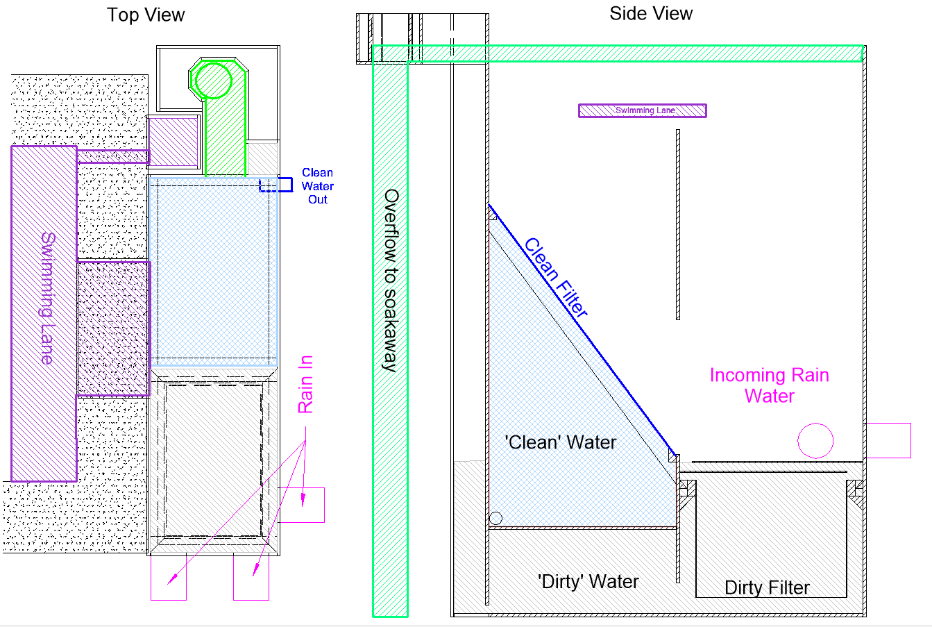
    This large box, measuring 1800mm (6feet) high, 1200mm (4feet) deep and 400mm (16inches) wide, with most of it buried (only 800mm (just over 2½ feet)) is above ground. It has three main pipelines (110mm diameter pipes) connected to the module, 2 running from the main house roof and 1 from the garage roof. There is also a fourth connection, directly to and from the swimming lane with the wide but narrow slot that is positioned 150mm below the top of the swimming lane. This slot acts as a overflow point for the swimming lane when it collects rain water and combines with the roof water and is filtered and stored away for later use, but also the swimming lane and pond can act as a buffer to store temporary surge water during freak thunderstorm weather conditions that would normally over whelm the underground soak-away module and give it time to handle that kind of volume of rain water.

    Many Days of Creating and Building Various Parts of the Filtration Module

    RainFilter


    We are making two modules, one is the main filter unit and other is a separate channel which is used to recirculate water in the swimming lane, drawing it from the bottom of the swimming lane and pumped up to the return channel which runs down the back of the swimming lane and empties into the pond at the other end of the plot.

    The filtration module comes in three sections, the first being the ‘dirty’ water collection chamber, the second section is the filter to provide the ‘clean’ water and finally the third part is a set of external vertical channels to provide paths for processing different types of water.
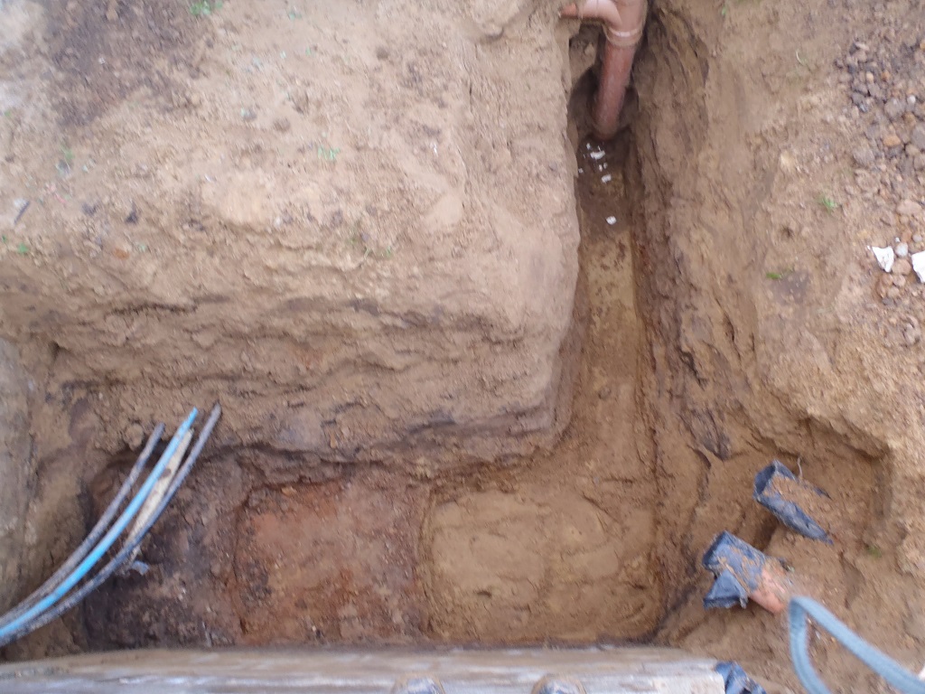
    One channel runs from the bottom to the top and is where the dirty water is extracted from the bottom of the filter module and pumped up to either the same return channel stream or distributed on the flower bed running along the fence behind the return channel, we haven’t decided which yet. The second channel of water, is the emergency ‘highest’ overflow point (sandwiched between the other two channels) for the whole system. This channel is connected to the main module by a slot positioned at 50mm from the top and all this water will flow down through more 110mm drain pipes, going into the soak-away module (buried under the driveway 10m away). We had to extend the existing underground pipeline to bring it into the correct position, when we install the whole module.

    Many Days of Creating and Building Various Parts of the Filtration Module

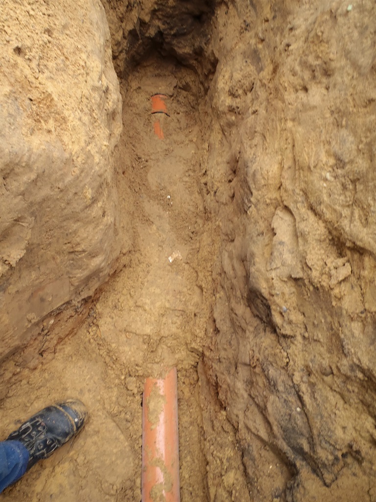
    Soak-Away-pipe-run-from-under-garage

    Many Days of Creating and Building Various Parts of the Filtration Module

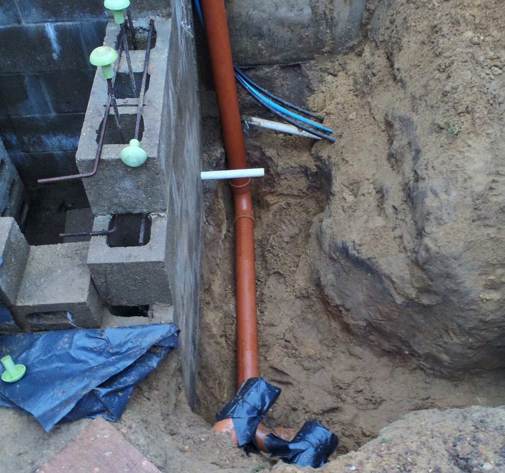
    then-Turn-towards-Fence-and-then-up-to-the-overflow-level-


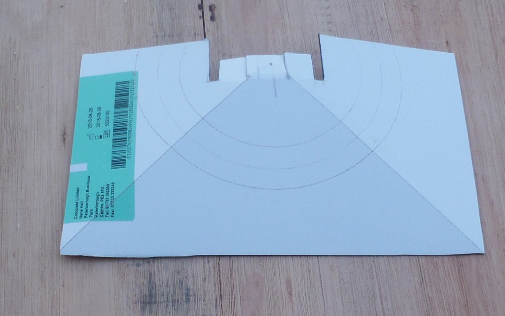
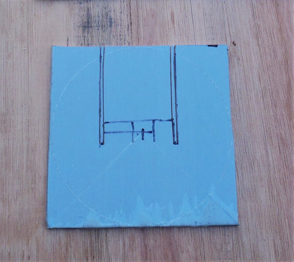
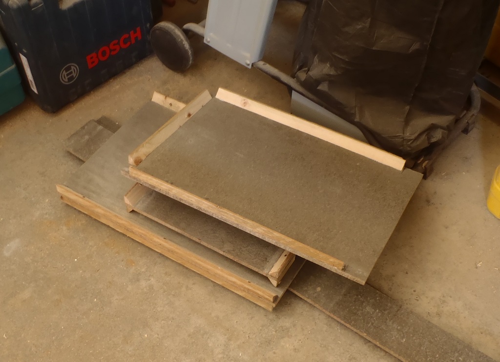
    The filter is constructed from fibre-glass and resin coated on 10mm thick cement boards, with wooden battens cut at 45degrees angles to help reinforce the corners and various internal shelves and baffles.
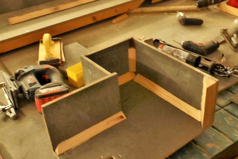
    We have so far created over a dozen pieces of various shapes, with the battens glued and screwed along various edges.

    Many Days of Creating and Building Various Parts of the Filtration Module

    Filter-Parts-Internal-bits

    Many Days of Creating and Building Various Parts of the Filtration Module

    Filter-Parts-Overflow-section

    Many Days of Creating and Building Various Parts of the Filtration Module

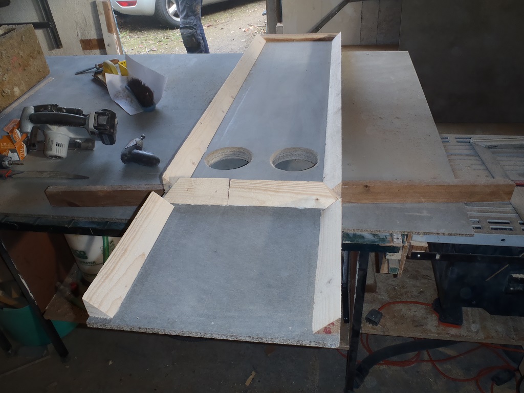
    Filter-Parts-Left-Side


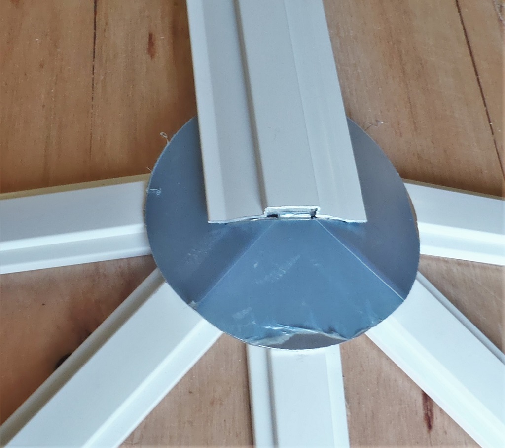
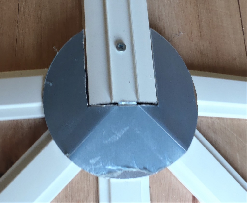
    We have started assembling it all together, only stopping at the point of putting on the ‘lid’ which actually is a side wall of the cabinet. We need to have access to all the internal surfaces to paint on the layers of fibre-glass and polyester resin.

    Many Days of Creating and Building Various Parts of the Filtration Module

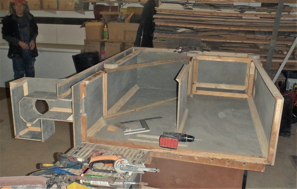
    Filter-Nearly-assembled


    We had quite a few interruptions to our work plus being a complicated piece of work, has accumulated to the twelve days so far spent on this task, but we should see it finish by another week. We are still waiting for our slates to arrive so we are not losing time on that job, and had to have this filtration module built and installed, so we can connect each section of the roof guttering system to the downpipe channels and all rain water would be immediately handled and taken away.

  • Slates on Section D and E Completed and Preparing the Guttering on Last Section At Last

    In these two weeks, there was a big disruption and stoppage to our work. The first week had only one successful day of work and that when we got the “D” section of the roof completed and got started on the “E” roof. The rest of that first week was spent recovering from the flooding we suffered during a very heavy rain storm, see Rain, Rain, Rain. for more details!
    The second week was more successful thank goodness .. ..
    First day, Monday, was spent in the workshop processing five more oak planks to make the remaining guttering pieces. We were short by three base pieces and two front ones. We had some of each type left over so we used those ones as our template to duplicate the extras. It was a 4 stage process to cut the various tongue & groove edges, bevelled angled edge and making the tongue to fit the fascia slot. We finished this task with a morning session on Wednesday.
    Fortunately, we had some dry days remaining so we got on with putting up slates up on the “E” section of the roof and got most of it covered by Thursday. We couldn’t go any further as we don’t have any access (safe access) from the other roof surfaces to finish off the section.

    E-mostly-slated

    E-mostly-slated

    The-ABDE-Junction

    The-ABDE-Junction


    Friday was an alternative day of work doing a hand rail for a family member and fitting it to their stairs. We made it using a 3metre plank of 27mm thick oak timber and planed it down to about 80mm wide with a gentle horizontally curving profile. Also we made a 45mm square post with another oak piece we had left-over from a previous job (the window sill).
    And finally, on Saturday, we rearranged two platform modules to extend our walkway and working platform to reach the remaining “H” section of the roof and a bit of the original “I” section where we started this whole job.
    We had to move some empty slate crates and also coiled up two plastic conduit pipes that had been buried underground along the back of the house for various old functions in the past.
    The afternoon saw the base pieces of the guttering cut and test fitted (but not glued) to section “G” and “H”, to rejoin back to where we started all those months ago!
    What was quite odd and amusing is that this last section along “H” saw the most wobbliest stretch of our fascia we have had in the whole of the roof and we had to make some minor adaptions to our base boards to make them fit in a straight line. Nothing complicated.
    (no picture as it got dark!)
    So next week, we will get the gutters finished, fibre-glass and black resin the final three corners, put in the rubber liners and then put up the breathable membrane and wooden battens up the roof.

  • Tested Rainwater Pipes, Finalising Design of Rain Filtration Module and Sliced Sheet of Plywood for Roof

    Yesterday, we wanted to test the pipework that we installed (for the rainwater collection off the roof) two years ago and make sure that the position of the ends of the pipe lines (two of them, one coming from the front of the building and the second one running along the back) which terminate just beyond the end of the swimming lane. It was a matter of levels and whether the rain water would flow reasonably easily down these pipe lines and confirm whether we need to readjust anything. We poured in about 120 litres of water (10 buckets) in a downpipe point furthest away and waited to see what happens. We had two right angled bends plugged into the two ends and pointed them down into a large 75litre trug. It took about 5 minutes before any sign of water arrived and only on the front pipeline. Nothing arrived on the back one. we left that to dribble over lunch as it was quite slow.
    After lunch, the large trug was full but not overflowing so we only got back about 75 litres of the 120 litres we put in, which means the pipework has very small dips in various sections which needed to be filled up before allowing excess water to flow pass. This will be trapped water for all time, but it is not bad at all, for this amount of water, considering our roof will be collecting 360litres of rainwater for a single millimetre of rain fall!! The only concern is for the pipeline running along the back of the building so we did some more tests by pouring in five more buckets of water in two more downpipe points behind the house, in between the Great Room and Bedroom 2. We did get some water to finally appear at the second pipeline but not much at all, most of the five buckets load went around the long way around the front of the building. This means that we have a small hump (a rise in the level of the pipes) somewhere between this point and the short run to the rain filtration module. The last thing we did yesterday in testing this out, was to carefully pour one bucket into the downpipe point (we label this one “LM” which is next to Bedroom 2 and Bedroom 1 – see map below) and we put two separate empty buckets under each of the two pipelines to find out what apportion of water went which circuit of the pipelines.

    In the morning, we discovered that a small amount arrived via the back pipeline but most of it went around the front pipeline circuit and filled up our bucket. The final test was to pour another single bucket in the final downpipe point we got along the back of the house, this time being the “IJ” corner (between Bedroom 1 and Bedroom 2) and see where it went. The result was that all of it arrived in the second bucket under the back pipeline route. We concluded that the hump is most likely in the 7.5metres section that runs along Bedroom 2, the “K” wall. We have earmarked a job request for later on, to dig up the sandy soil and see if we can level out the hump in the pipework, but only if it is possible. It is not the end of the world as the rain water will still be delivered to the rain filtration unit but sometimes more slowly than it ought to be.

    Anyway, while those tests were being done, we also got on with the designing of the rain filtration module and one aspect of the system, was the slow draining of the “dirty” water, or the first flush of rainwater off the roof, which we don’t want to keep as it could very well contain chemicals like herbicides and fertilisers, blown on the wind from our local farmlands. But the trick is to make this dirty water drain away so slowly that it would take a week or two to go and it hadn’t been topped up with more rainwater. This suggests that we are getting a dryer spell, like 2 or 3 weeks, especially during the summer and there would be more chance of a higher concentration of chemicals landing on our roof. We don’t want this stuff in our storage tank and being used in our house like flushing the toilets or providing recycled water for showers and washing machines. Hence why we want to “throw-away” this dirty water into our soak-away module instead.
    One method is to have a plug of fine sand to control the flow rate and we did some further tests yesterday evening, using a 100mm diameter pipe and putting a 100mm depth of sand in the bottom (the end covered in a geotextile material to hold in the sand) and then pouring a quantity of water and timing how much water drained through in a given amount of time. our first test showed that the water was flowing through at about a rate of 6litres per hour which is rather too fast for our purposes. We would like to slow this down to about 1litre per hour so that our “tank of dirty water (which is currently designed to hold about 240litres) would take about 10 days to drain away completely. Our second test in another drain pipe with a different plug of sand but with a taller column of water to emulate more closely the reality of our filtration module but when we put in the water this time, it didn’t flow hardly at all! Very strange and we wondered if we managed to get silt on the top surface of the sand and effectively blocked it, or perhaps the different sand had much finer grain sizes which also served to block the flow of water too.

    We walked away from that, discussed the problem and considering alternatives.
    Today, we concluded that it would be far more reliable if we used a small water pump instead and have it controlled by the computer in the house, and pump the water up and into leaky hose pipes running along the back of the swimming lane where there will be a small strip of soil for growing various shrubs and climbers.
    This does mean that our design for our filtration module is now much simpler and we can narrow down the width from our original 600mm width to a more practical 400mm wide and extend the whole unit backwards towards the mass wall and the fence line. All the electrical apparatus, sensors and control gear can be held in one place near the back of the module and the water can flow backwards toward the location of the pump.

    Tomorrow morning, will see the design fleshed out and finalised, but for the remainder of today, we got on with slicing up the plywood sheets we bought last week into narrow strips, ready to build up edges of the Hip portions of the roof plus also the ridge lines too. This build up is necessary to help support the tile battens when we are doing the fiddly angled edges along the hips (which has an extra “flashing” layer added on top of them) and something similar for the ridge lines (but a little simpler).
    So we bought six sheets of 15mm thick plywood which got sliced up into 100mm wide strips (actually, we only needed five of the sheets) to produce 60 strips in total. Then we got out most of the left-over strips of 12mm thick plywood out of the garden shed (these came from the rafter building stage) and sliced them up into 175mm wide strips. These left-over pieces gave us the equivalent of 39 and a bit full length strips (2.44metres long) so we only need a further 53 strips to satisfy our requirement of making 92 strips. We will conclude that task tomorrow, along with making 30 strips of 150mm wide (12mm thick) ones too. All these pieces are being stored in the middle of our house under our gleaming new Skylight!!

  • Dug Hole for Filtration Module

    This afternoon (after being diverted in the morning to other commitments) we started the next stage of dealing with the rain water coming off the roofs (main house and garage), by digging a hole at the end of the Swimming Lane and next to the garage.

    Dug Hole for Filtration Module

    Rainwater-Filter-A-Hole-in-the-ground


    We will be building a water Filtration Module to receive the input from the roofs (in three 100mm pipes), entering a settling tank section first and then being filtered so the fairly clean water is collected and stored in our underground rainwater tank under the garage.
    This module will be attached to the end of the swimming lane, with additional connections for surge water to flow into the swimming lane and pond but also a connection for drawing the water from the depth of the swimming lane and feeding it up to the return channel via some form of a “water feature”.
    We had to dig down to the lowest pipework which feeds to the rain soak-away module, the depth being 1.2metres (4feet) down. The other pipe (the white one) is the feed to the rainwater tank which is at a depth of 700mm below ground level and the bottom of the swimming lane is 800mm down to the foundation level.

    Tomorrow, we will measure everything to confirm these numbers and then finalise the design of the module which will be made of cement boards and fibre-glass resin layers with internal removable units so we can clean them.

  • Skylight Unveiled!

    This morning, under a cloudy sky, we unveiled our spanking brand new Skylight to the world!! We went and pulled off all the final protective cling film coverings off the polycarbonate panes!! It had a layer of water from the morning dew so we got rather wet!

    Skylight Unveiled!

    Skylight-Revealed-1

    Skylight Unveiled!

    Skylight-Revealed-2

    Skylight Unveiled!

    Skylight-Revealed-3


    This concludes the job of putting up our Skylight. Here is a breakdown of our timesheet on the various aspect of the task of creating this skylight module:

    • 30 working days to build the framework and paint it
    • 16 working days to install the framework and the glaze it

    We started at the beginning of August and finished today on the 6th October, with a total of 46 working days spent on the Skylight!
    Here is a super-fast time elapsed video of the skylight being installed.

  • Ridge Bar All Rain Protected and Bird Disruptor Created and Installed

    We carried on making the second of the two special end caps for the ridge bar, shaped to cover over the five rafters all coming into one point at the end of the central ridge bar. After filing and rubbing the edges smooth, we then sprayed them both with several layers of metal white paint and, to speed up the process, put them into our oven at 50°C to dry them quickly.
    Meanwhile, we took up the white rain guard covers for the ridge bar and using the two longest lengths, we fitted them at each end (making a clearance hole for the threaded rod) and loosely fitted them. We weren’t ready to snap them down just yet. The next piece was measured to meet (and go just beyond) the middle threaded rod position but we discovered that about 1metre (3feet) was slightly distorted at one end and when it met its sibling piece, they were obviously mismatching.
    So after lunch, we decided to used a another piece of the rain cover, left over piece from doing our fourth and final piece and replace the ‘damaged’ section with a fresh and clean piece. It now aligns up very nicely!
    Then we went along the whole length of the ridge bar and using a pair of pliers, we twisted very slightly the metal edge at every 500mm, this edge being what locks the rain cover down. It was too loose and then bends make it tight (we had to hammer it in place!), we don’t know whether it is a design flaw or the manufacturer expected us to do the trick of ‘denting’ the metal edge, we don’t know? shrug shoulders!
    Now we were ready to apply the white PU sealant to the end caps (these were screwed into place) and then proceeded to snap the rain guard covers into place for the final time. The joints had some further white sealant applied and this included around the holes that had the threaded rod poking through too.

    Ridge Bar All Rain Protected and Bird Disruptor Created and Installed

    Skylight-construction-complete


    Next, we returned to our workshop to create our Bird Disruptor (We have noticed the bird’s really liked perching on the skylight so we decided to add some deterrent in the form of 3 fine wires stretched just above the ridge to give birds a scare when they try and land on the ridge) . We made three 200mm long supports, using stainless steel angle iron and then drilled one big central hole (for the 10mm threaded rod) and another three tiny holes (for the thin wires) and cut half way through one flange at 66mm (third the way in from the ends) and this allowed us to bend the piece with a 15degrees angle, to follow the slope of the roof. After grinding and rubbing all the edges and corners, to make it smoother and softer, we then took them up to install it on our skylight, along with three length’s of 1mm thick stainless steel twisted wire and stainless steel nuts and washers to clamp them into place on the three threaded rods.
    Ridge Bar All Rain Protected and Bird Disruptor Created and Installed

    Bird-deterent-system-One-End

    Ridge Bar All Rain Protected and Bird Disruptor Created and Installed

    Bird-deterent-system-Middle-support

    Ridge Bar All Rain Protected and Bird Disruptor Created and Installed

    Bird-deterent-system-Other-end


    Tomorrow, we will then do the final ‘grand reveal’ by going along and pulling off the last of the protective cling film covers on the polycarbonate panes and give everything a clean and polish to make it sparkle! Hopefully we will have some good sunny weather!

  • All Rafters Now Covered with the White Rain Guard

    This morning, we finished off the last three rafters on the right hand end of the Skylight (two diagonals and a straight) and put on the last four aluminium edge protection strips too.
    We were interrupted by two deliveries, one for the fibreglass valley channels (16 lengths of 3metres each) and the second delivery was for a dozen sheets of materials (some 18mm OSB, 15mm plywood, 10mm cement board and a 12mm high grade plywood)
    After lunch, we went around all 33 rafters, putting a line of white PU sealant at the top end where they met the ridge metal bar and then snapped on the white rain guard and applied another line of sealant. That took about an hour or so.

    All Rafters Now Covered with the White Rain Guard

    Joints-sealed

    All Rafters Now Covered with the White Rain Guard

    Covers-on-rafter-bars


    The rest of the afternoon was spent designing and making another rain guard cap but this time for the two ends of the ridge bar. We first built a wooden mock-up model of the ridge metal bar with all its neighbouring rafters coming in like a star and then using a piece of cardboard, we cut and bent it into a three angled shape so it will fit into the end and provide protection from the rain.
    All Rafters Now Covered with the White Rain Guard

    Cardboard-model-of-cap

    Cap-half-made

    Cap-half-made


    All Rafters Now Covered with the White Rain Guard

    Rain-cap-for-end-of-ridge-1

    All Rafters Now Covered with the White Rain Guard

    Rain-cap-for-end-of-ridge-2


    We managed to make one today and we will make the second one tomorrow, give them several spray coats of white metal paint and then get the whole Skylight finished with the installation of the rain guard covers along the central ridge bar including the two custom made end caps!

  • The Two Ends of Skylight Almost All Done

    We resumed the work of completing the two ends of the Skylight today, we had our four triangular pieces ready for installation, after the overnight job of gluing on the protection edge strips, for the Great Room end. These four plastic glazing panes, along with three rafter bars (one straight and two diagonal ones) were taken up and installed into place. The diagonal ones had to have two 45degrees slices cut off the top end (like an arrow head) before they could fit snugly into place.

    P-End-Glazing-complete

    P-End-Glazing-complete


    After lunch, we started on the other end of the Skylight and proceeded to slice up the final two square sheets of the polycarbonate material into the last four triangular pieces, this time, it was a little more complicated because we have a little kink in the Skylight and this end has a twisted “skewed” arrangement of the rafters. We managed to get the measurements all sorted and duly arrived with our cut pieces which went straight up on the roof, clearance holes drilled and fitted into position. We ran late so we could get these last four “windows” finished which only the three rafter metal bars to do in the morning.
    The Two Ends of Skylight Almost All Done

    H-End-Windows-fitted


    Tomorrow, we will do those rafter bars and then start applying more sealant around all the joints between all the metal parts and then snap on the white rain covers with more sealant to provide multiple layers of protection against rainwater getting in.

  • Ridge Bar Complete and First Four Triangular Glazing Panes Cut

    We finished off the installation of the Ridge bar this morning. The last section, the fourth one, was 4.494 metres long and we now have a complete ridge clamping down all the 25 windows (13 on the front and 12 on the back) with a total length of 13.5metres long.

    Ridge Bar Complete and First Four Triangular Glazing Panes Cut

    Ridge-complete


    Then we got down to the complicated process of measuring the triangular framework so we could cut the polycarbonate sheet into the required shape and size. We started on the Great Room end of the Skylight and using our large framing square, to validate the assumption that the framework was indeed “right angled” and that we could and did take measurements of the vertical distance and the horizontal direction too but we also had a long straight aluminium “ruler” where we could verify the hypotenuse length when we transferred the numbers to our polycarbonate sheet. Using a long guide bar, clamped down and we carefully cut the plastic with our battery circular saw. We took the first one back up for a test fit and .. it fitted!
    We repeated this over again for the next three cuts and we now have four triangular pieces!
    They all then had their six clearance holes drilled into them and the protection metal edge strip glued, ready for these four to be installed tomorrow.
    The last little task was to measure and cut the middle rafter bar to length and screw on its end cap, also ready for tomorrow.
    So in the morning, we will do that and then deal with the two diagonal rafter bars which has to have a double angled edges taken off them to fit into the correct position .. all very fiddly work!

  • Back of Skylight Glazing Completed and Ridge Bar Almost All Done

    This morning we continued with the job of installing the glazing panes along the back of the Skylight and we now have 25 out of the total of 33 “windows” completed. It is just the two ends that have four triangular shaped windows in each to do and we would have the whole thing done.
    After lunch, we went around putting in all the other stainless steel fixing screws in the rafter bars before tackling the installation of the central ridge. We approached the task by doing the two ends first where we had to get a 13mm clearance hole in the exact position so the threaded stainless diameter steel rod will poke though without binding up. We also had to chop off a small damaged section of the aluminium extruded bar (it looks likely for the “accident” happened during manufacturing) but we had plenty to work with. We finished off the day with fitting the third ridge bar which came up to the central threaded rod. The joint was coated in white sealant to ensure a waterproof connection.

    Back of Skylight Glazing Completed and Ridge Bar Almost All Done

    Main-glazing-complete-most-of-ridge-installed

    Back of Skylight Glazing Completed and Ridge Bar Almost All Done

    Mostly-glazed


    Tomorrow, we will do the fourth and last section of the ridge bars and then start work on doing those more complex triangular windows!

    Here’s an extra video showing the fitting of one window in real time!