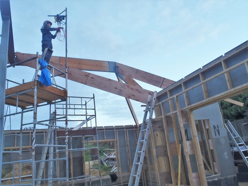
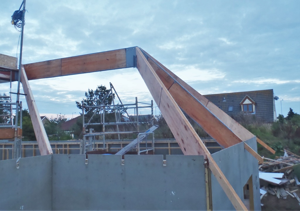
Over the last three days, we have been measuring, calculating, sorting, adjusting, calibrating and humping all sorts of stuff that are all aimed towards the next stage of creating the Rafters that makes up the majority of the roof structure.
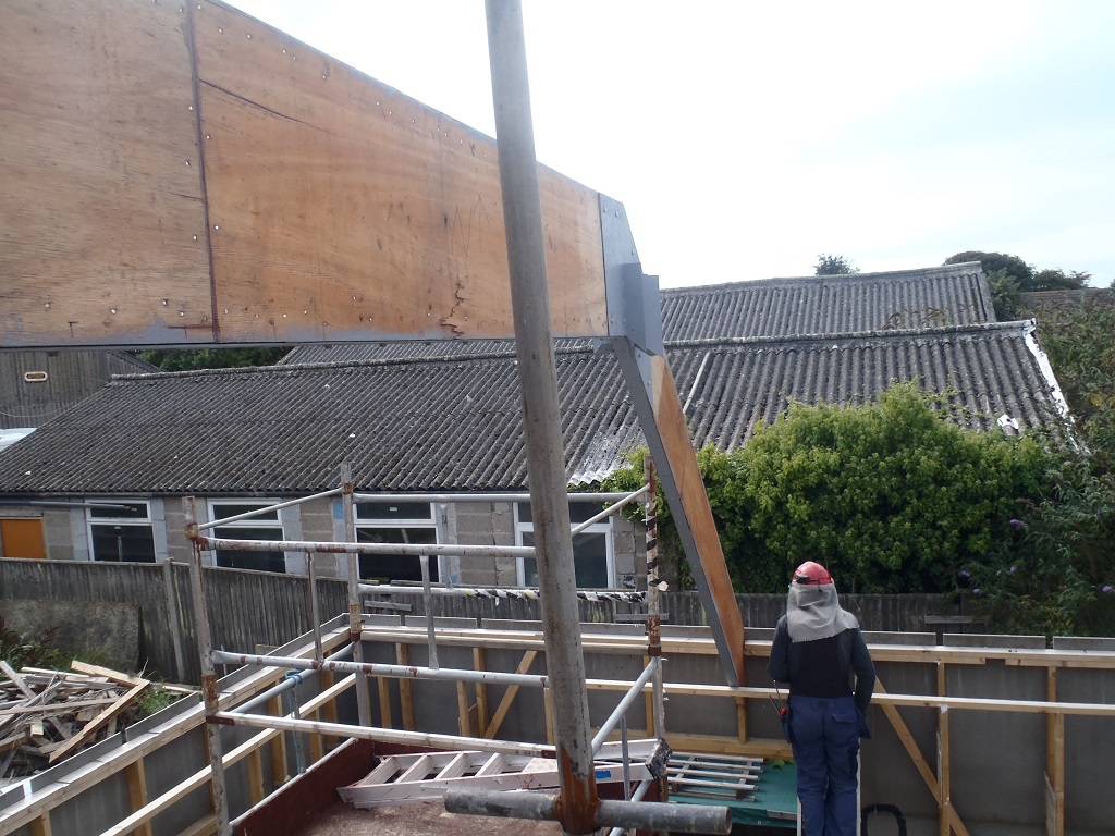
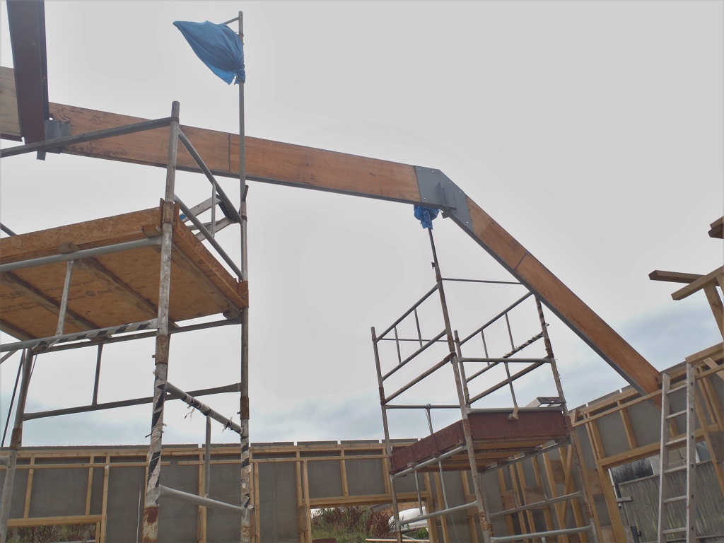
We started on the “A” wall and measuring the distances from the wall to the PA diagonal rafter and also up on the steel I-Beam too. It was proving difficult to get an accurate measurements. Even after we built a laser projector so that the detector would find the laser beam up on the PA rafter but even this proved a bit wild. So we waited for the darkness, in order to see the red laser beam directly shining a line right on the wood surface and drew a pen mark at those points. The following day, we then measured these marks and even this was a little wobbly too. after careful thoughts and discussions, we concluded that the only reliable measurement was the rafter that fits up onto the steel I-Beam, this one is called A6. This measured as 4815 mm. we moved along to A16 and measured that one too, which came out as 4840 mm. we know that the steel I-Beams are straight so we calculated that for each subsequent rafter, we added 2.5 mm to the length.
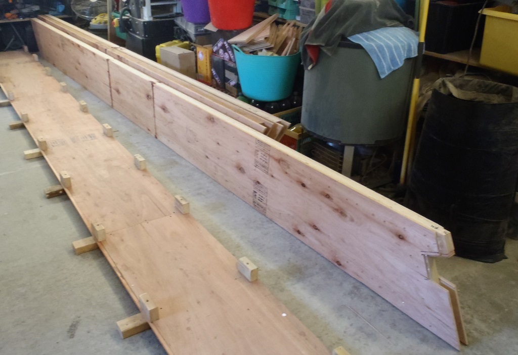
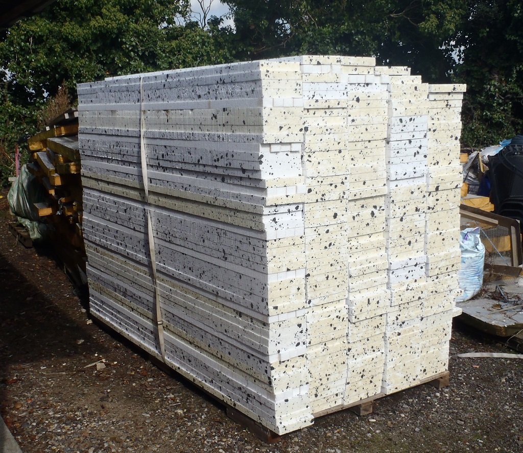
Then we humped into the workshop 21 lengths of the 89mm CLS timber, but we discovered that most of the timber was rather wet from rain showers we had over the last few weeks and the wind and sunshine has not been strong enough to dry it off fast enough. We will need to sort out the pile (see previous blog report). Anyway, we needed to put 17 of these CLS timbers into the Bird’s Mouth template. But we needed to adjust and recalibrate the template so that the Bird’s Mouth was coming out at the correct depth, size and angle which is 32 degrees for the “A” wall. We verified that all was correct now, and then proceeded to cut these Bird’s Mouth and Angled ends on the 17 lengths. After that, we put 12 of these into the “scarf” joint template plus 12 shorter pieces and today, we glued and screwed together this scarf joint on these 12 length (A scarf joint allow two pieces of timber to be glued on a long diagonal resulting in a longer piece of wood). They are now drying overnight.
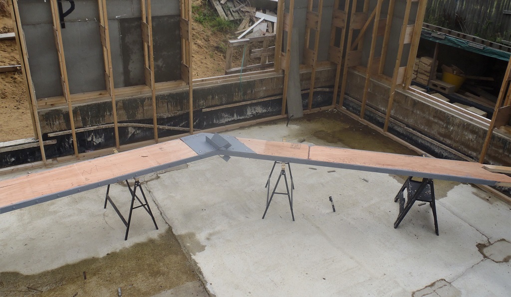
To confirm that we were on the right track, we took outside one of these new scarf joined pieces and cut it to length then we went to place it up into the A6 position and discovered that the length was too long. We then realised where our calculations were being misapplied so we have updated our spreadsheet to take this into account.
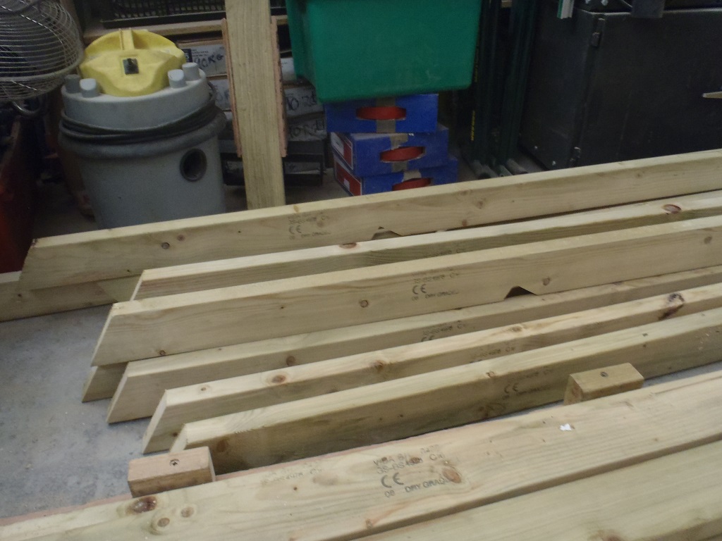
12-Extended-top-flanges-with-birds-mouths
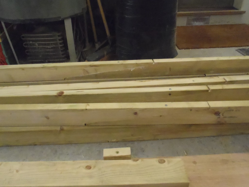
12-Extended-top-flanges-with-scarf-joints
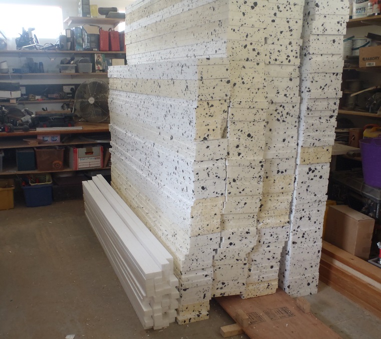
We are learning! Phew! Tomorrow, we will go through the task of slicing up all the plywood sheets into 400mm wide strips and then put the resultant huge pile back under cover outside!