Just before lunch, we tried out our new Bevel Slicing machine for the first time on the smallest rafter A22 to see how it went. The machine and template performed very well, we are glad to say! We took out this little 1 metre rafter outside to test fit it and it went in not too bad. it was slightly too long but that was because the original finished rafter ended up being 4mm longer than expected, which included also a local variation in the Kerb section of the Skylight.
After lunch, we removed these 4mm off the top end of the rafter and tried again and it fitted much better this time. we went along with our spirit level to test the kerb side of the skylight to see if any more had more than usual variations but the rest were within tolerance.
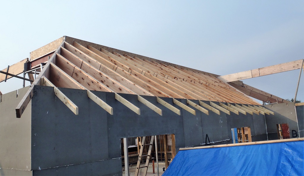
We then used the Bevel Slicing machine on the next rafter, the A21, but double checking the length first which turned out to be ok. This rafter was test fitted as well and it was fine straight away. We decided at this point to bring out all our tools and glue etc. to install these two small rafters up so we did that, applying the glue and then nailing them tight into place. We carried on with the longest rafter, the A18, next and got that one up into place first time too.
The rafter A19 and also A20, proved to show up some problem with our Bevel Slicing machine where the saw blade seems to be bending away from the straight line and we don’t know why this is happening. We had to finish off the bevelled ends using our power planer. We got these two final (of this local section of the roof) rafters up and installed.

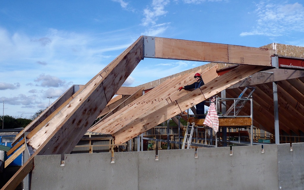
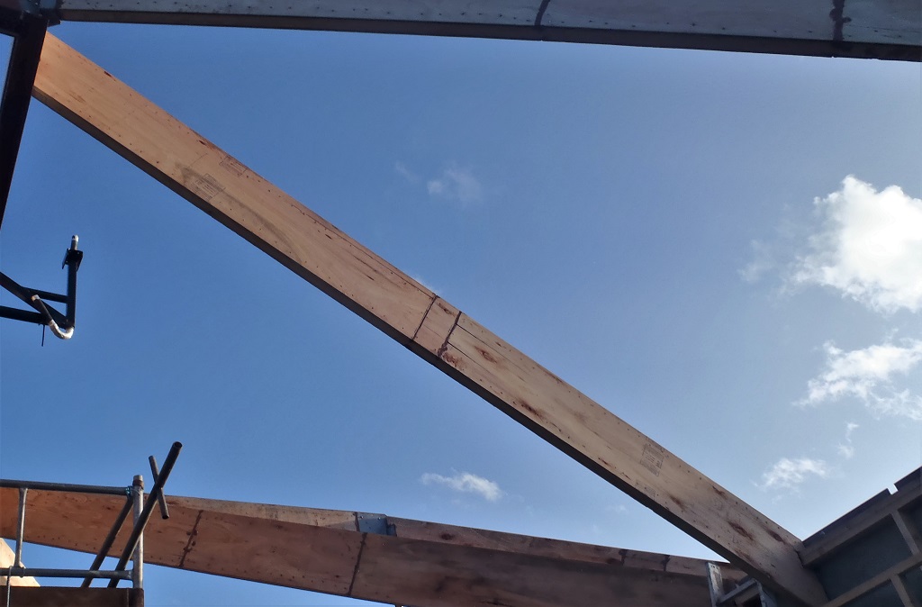
Rafters-A19-to-A22-Installed
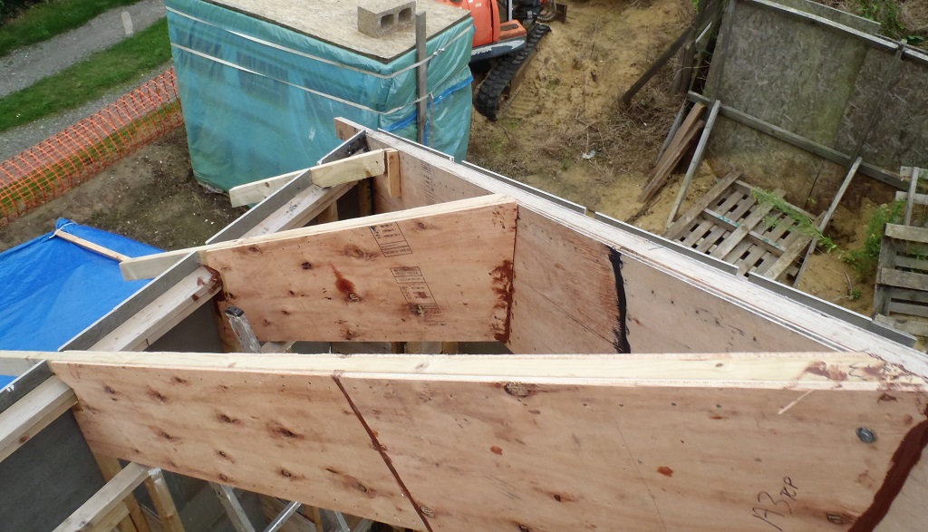
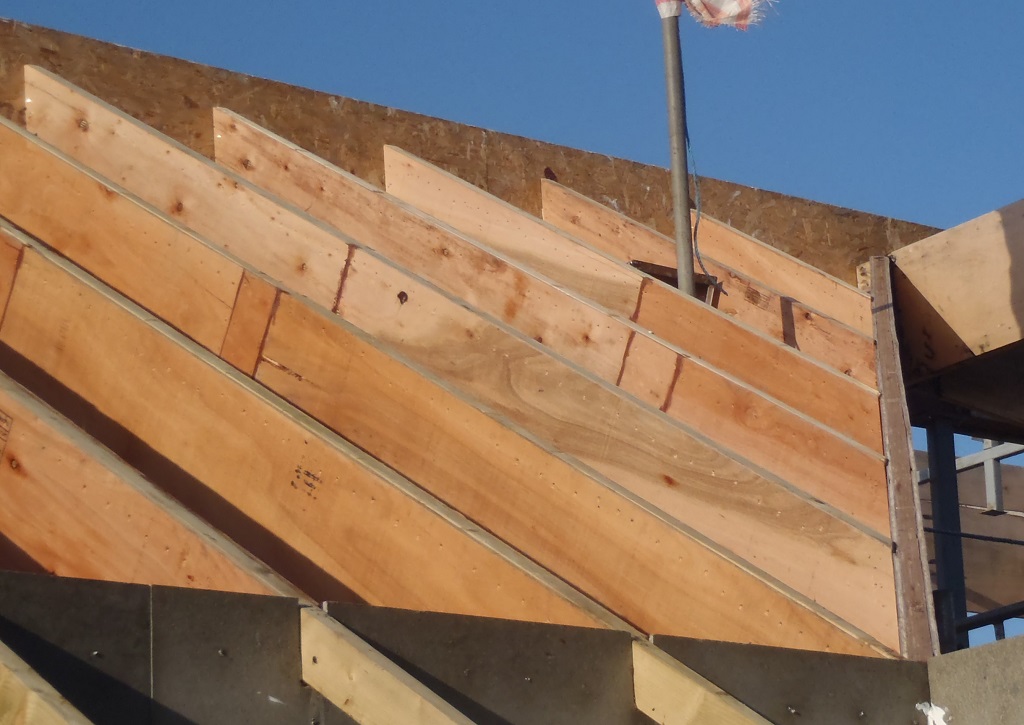
It was quite dark when we finished, especially after we have brought in all the tools, compressed air equipment, wrapped up the lift winch motor again and tidied up after ourselves! We left the tall winch support pole in the tower, sandwiched between rafter A20 and A21 and we will deal with that on Monday.
As you can see, we hope we can get the tower from out among the rafters .. or we will be in trouble! – grin!