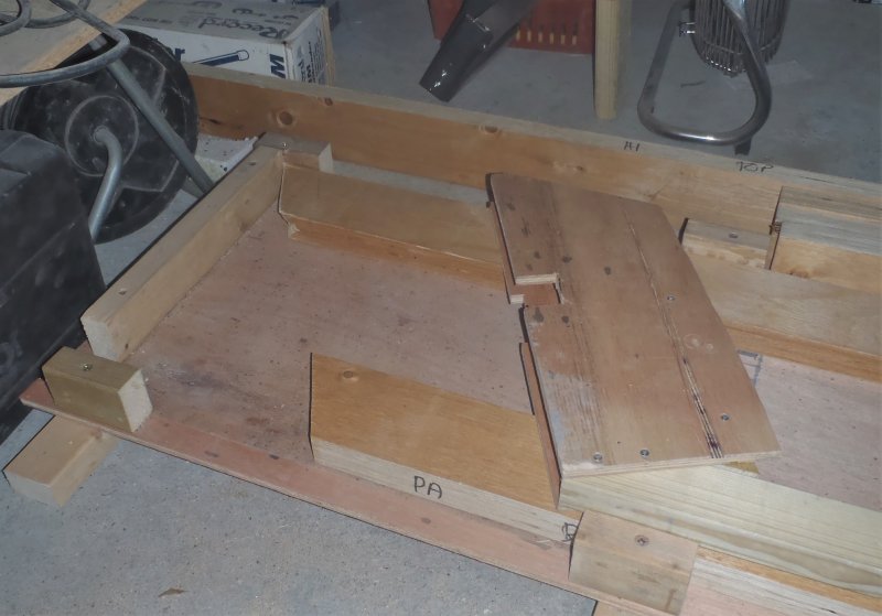
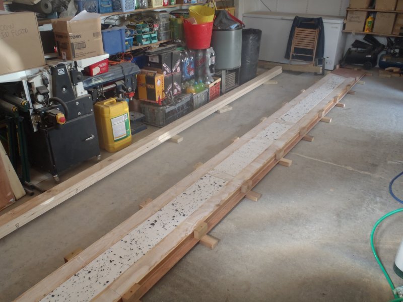
We carried on today with the PA Hip LVL Rafter, making internal noggins (four of them, one at each end and two in the middle at the joints of the webbing). Everything then was vacuumed (the whole workshop, template, LVL timber, plywood webbing and everything else too!), but before we put the rafter together, we took the webbing and copied over the shapes of the cut-outs to the next set of webbing for the HI rafter we are going to do next. This rafter is the same in almost all ways as the PA rafter so we just copied over the pattern to save us some time.
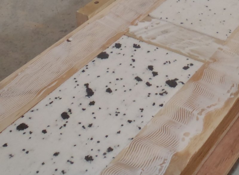
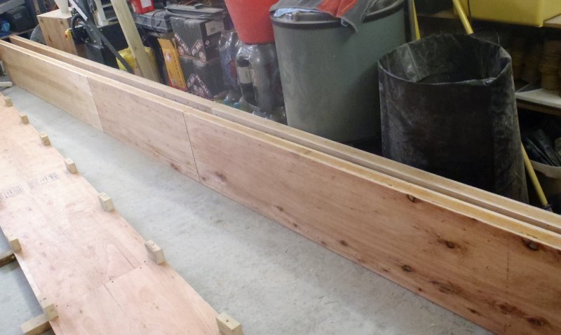
Next, we assembled the whole rafter and got our glue machine going and laid down a layer of glue along the LVL timber and noggings and sandwiched the plywood webbing on top, and went down both sides with the squeezer and nailed it tight together. We turned it over and then inserted the polystyrene foam pieces and vacuum it again and finally applied more glue to the this side of the LVL and again sandwiched the second webbing layer with the squeezer and then nailing that side together as well.
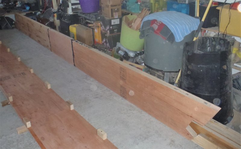
Rafter-PA-Finished
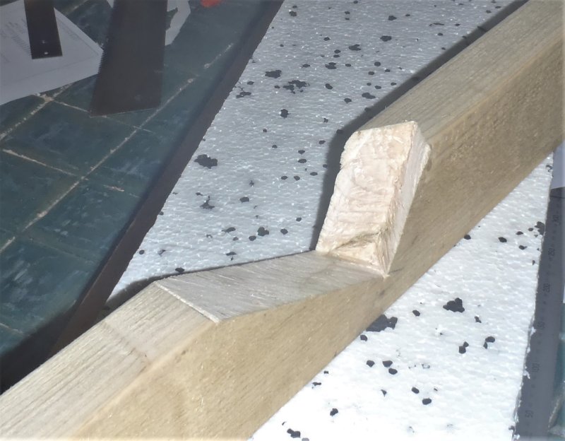
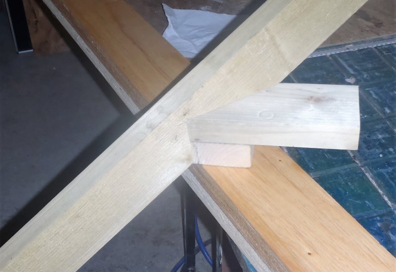
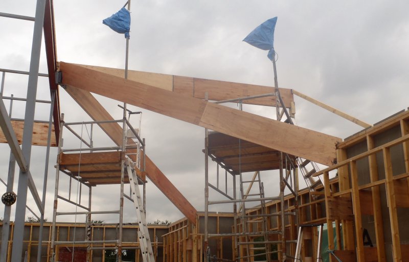
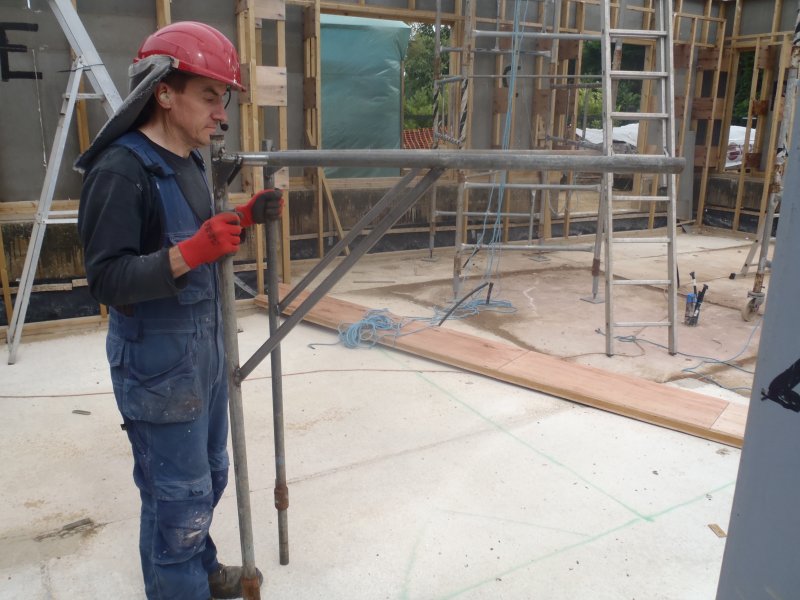
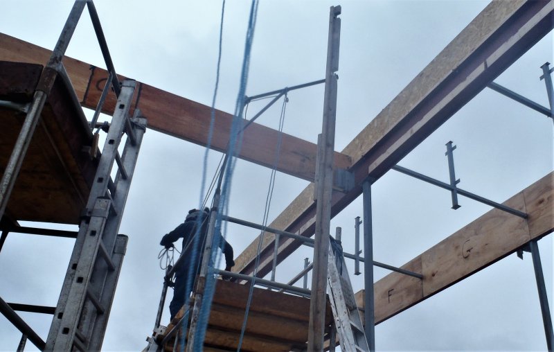
While that was drying, we went outside to set the three corners we are doing, cutting to an exact length for each leg so it fitted just nice and tight between the foot-plate and top-plate!!
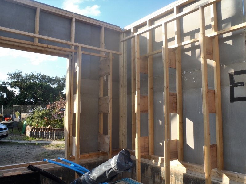
Corner-post-in-place
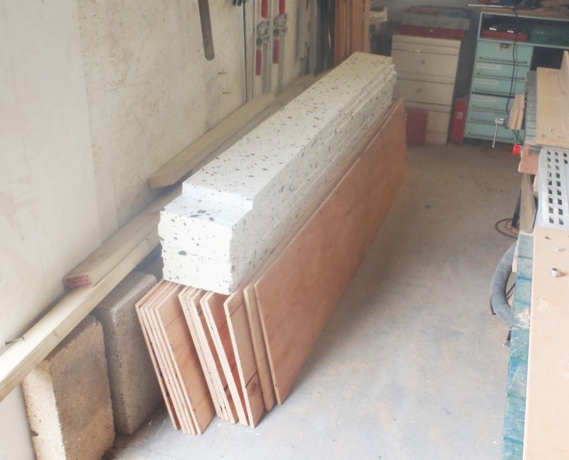
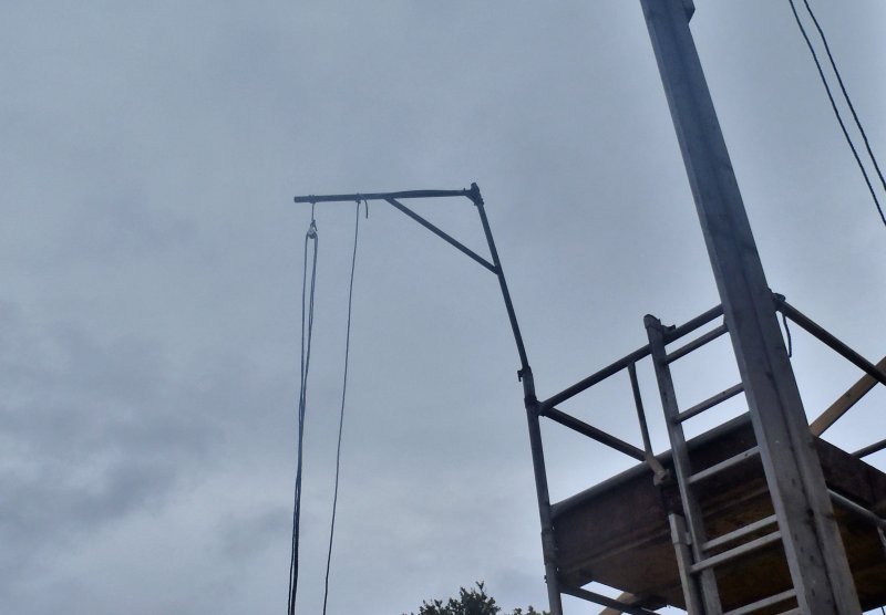
Also, we put on the new wheels for the second scaffolding tower, after reducing the height down by one section so it can more easily fit under the diagonal rafter beams.
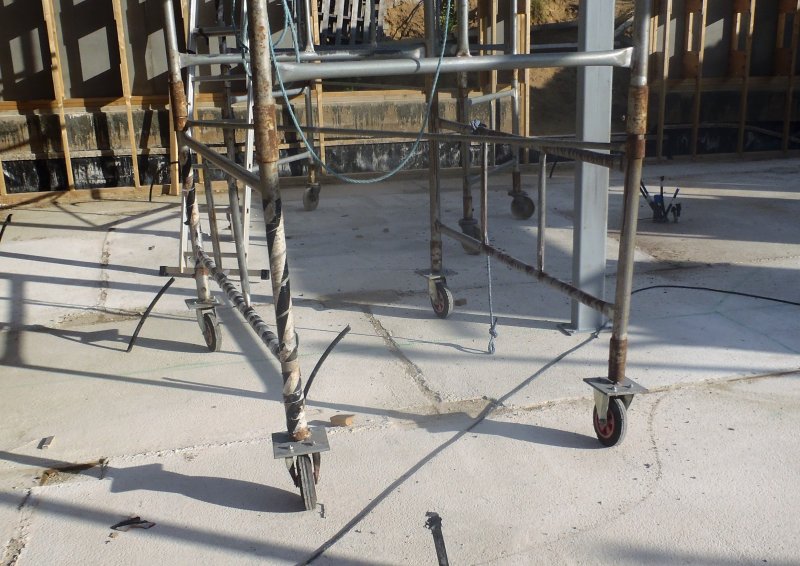
Wheels-added-to-other-tower
Finally, to finished off the day, we sliced and trimmed the funny cut-away piece on the HI corner, removing a small vertical piece of the cement board, just like we did on the PA corner. Tomorrow, we will go out with our new PA rafter and see if it will fit in according to the plans! We have our fingers crossed ! Grin!