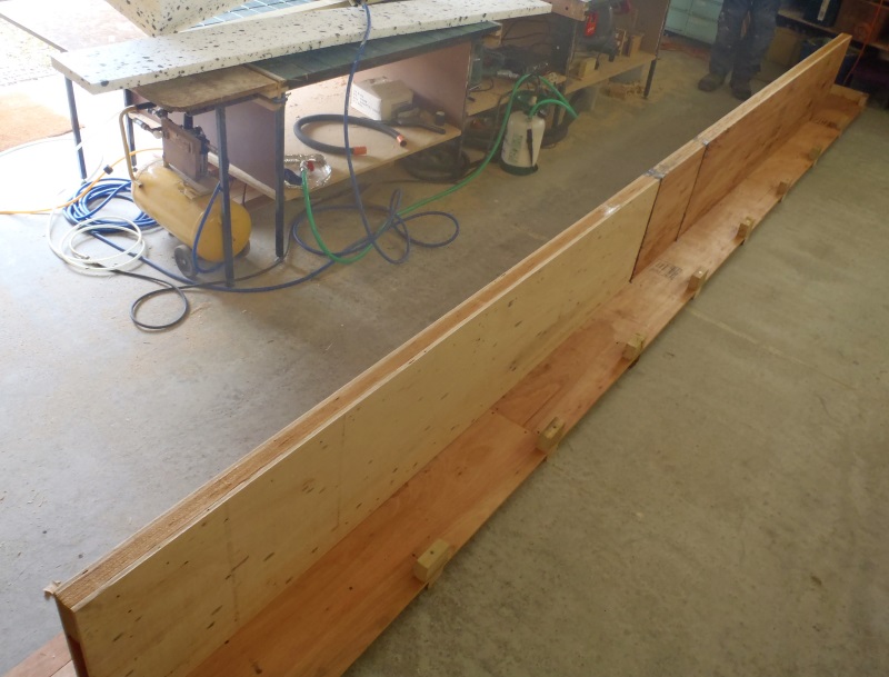
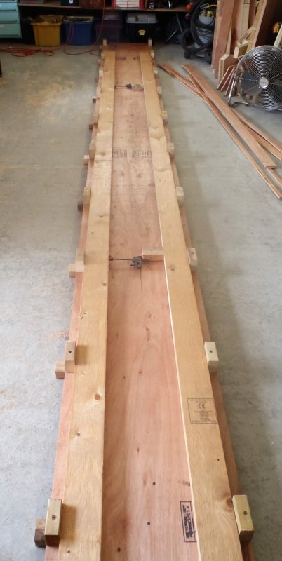
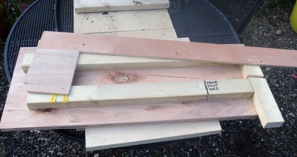
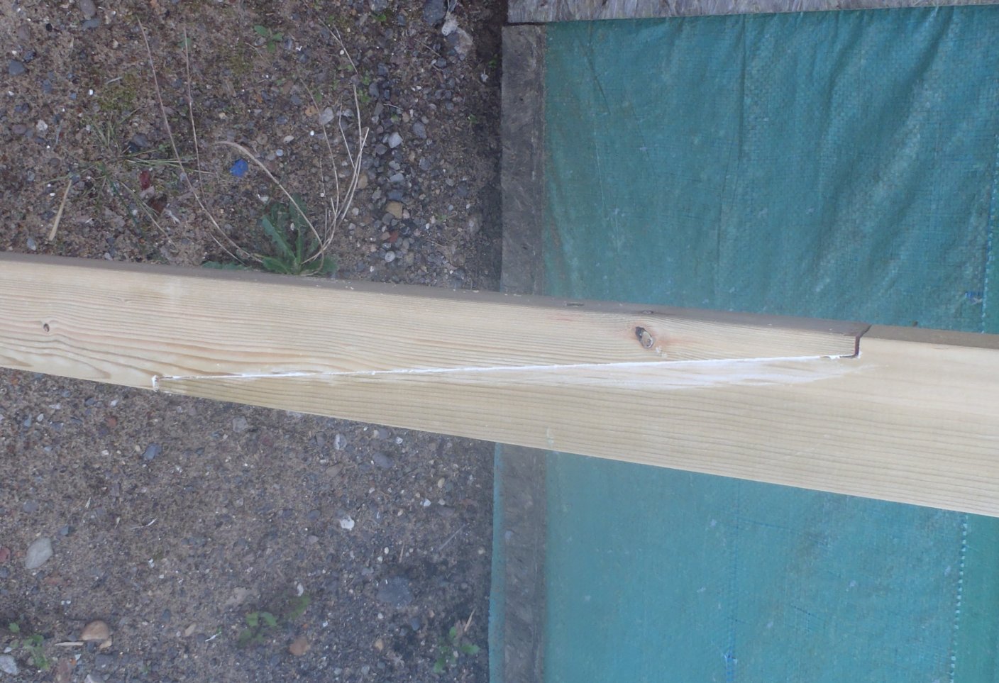
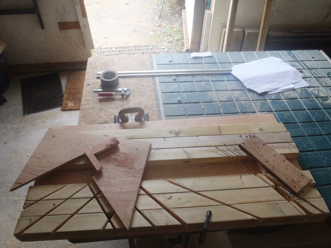
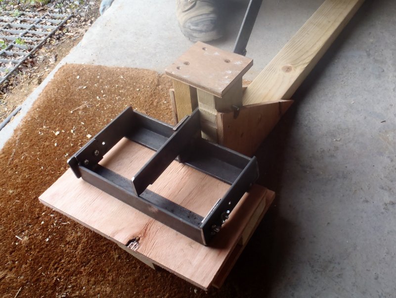
Today, it was the task of taking out our C Ridge beam out and installing it into place. But first, we had to cut away some little bits of wood at the end of the beam that goes next to the steel I-Beam (to clear the sticking out flanges of the I-Beam), and also insert some filler wood pieces so that the fixing nails in the side of the metal bracket will be securely and bite into solid wood.
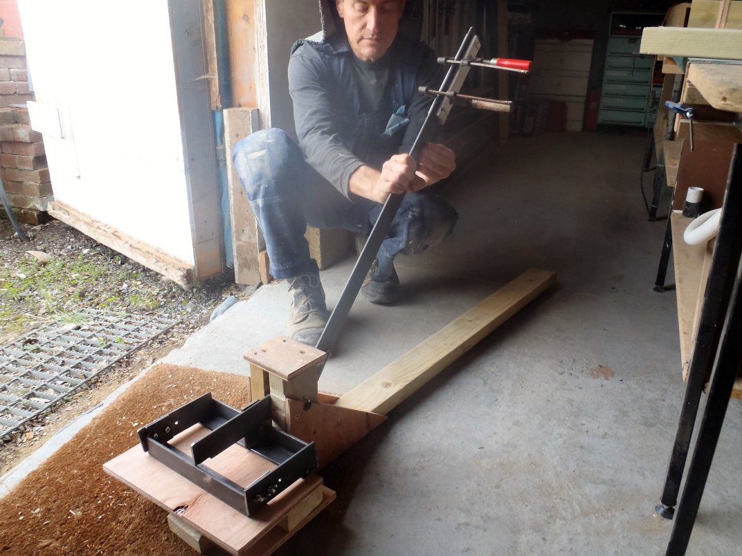
Next, we weighed the whole beam on our scales and it came in at 61kg which is a fair weight but we could handle it fairly easily to take it outside and lay it down ready for hoisting up our scaffolding towers. First, we tried hauling on rope by our own muscle power but it proved rather difficult to lift and keep the beam in control, meaning not letting it fall back down again!
We then switched over to our old method of using our mains powered winches on our existing metal poles jammed into the corner of the scaffolding tower and hoisted the beam up nice and easy. We managed to swing the beam around and have it resting across our two towers.
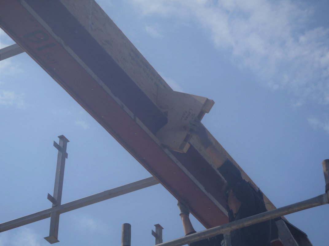
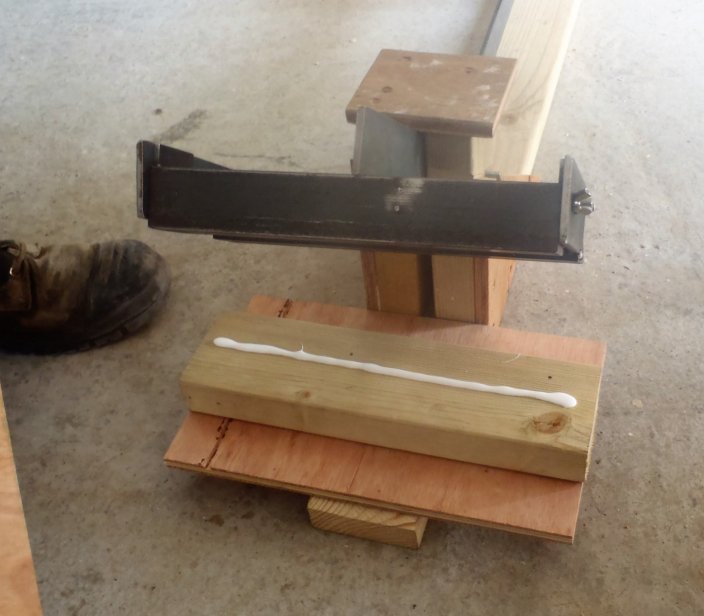
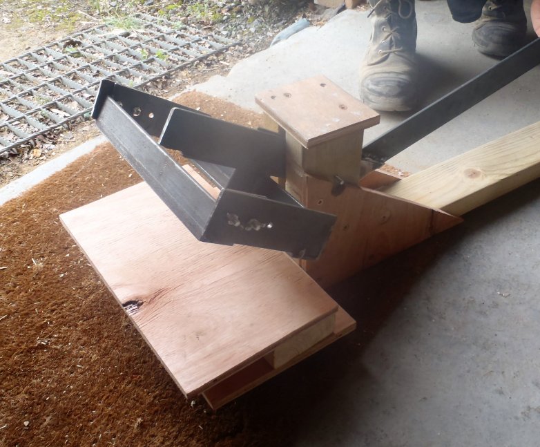
Here we found that it was tricky lifting each end up by ourselves into the bracket and onto the post (on the C wall) so we ended up taking turns to be both at one end at t a time and help lift it in place. We did some slight removal of wooden material at the I-Beam end so it would fit into the metal bracket and sit more firmly back to the Kerb etc. and then we applied lots of silicone glue to the whole bracket surfaces and wooden ends to slide the beam into it final position. We then applied more glue at the other end on the post and fixed two side bracing supports to lock everything together including six fat nails in the sides of the metal bracket to anchor the beam firmly in place.
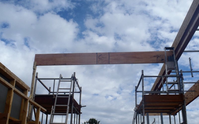
C-Ridge-in-place
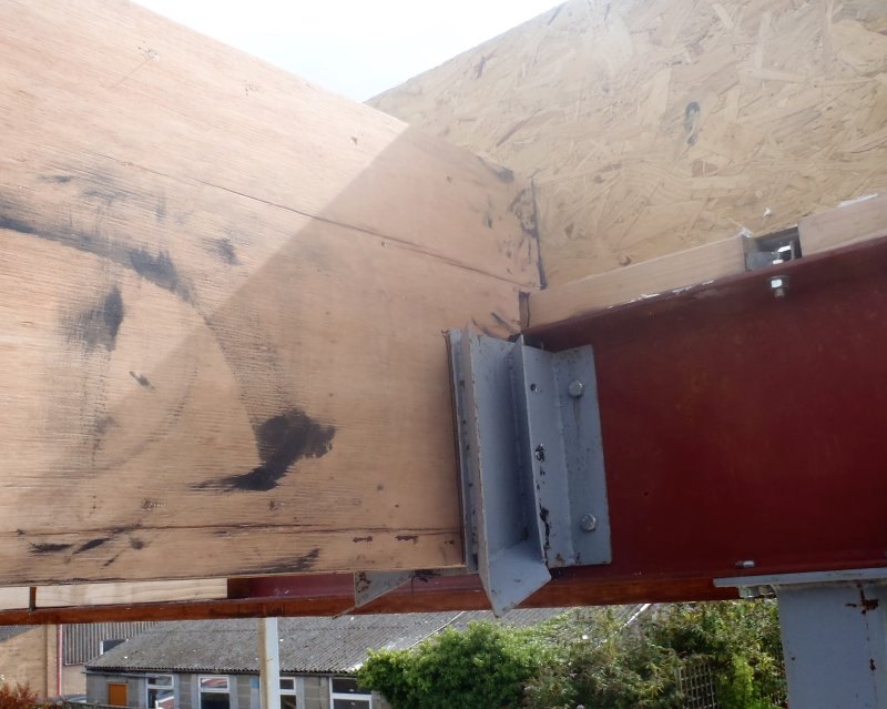
C-Ridge-in-Metal-Bracket
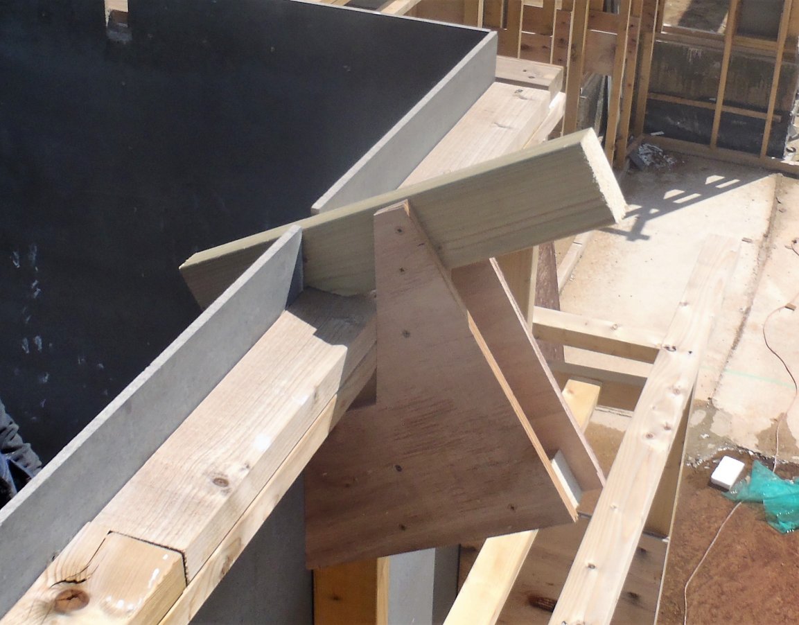
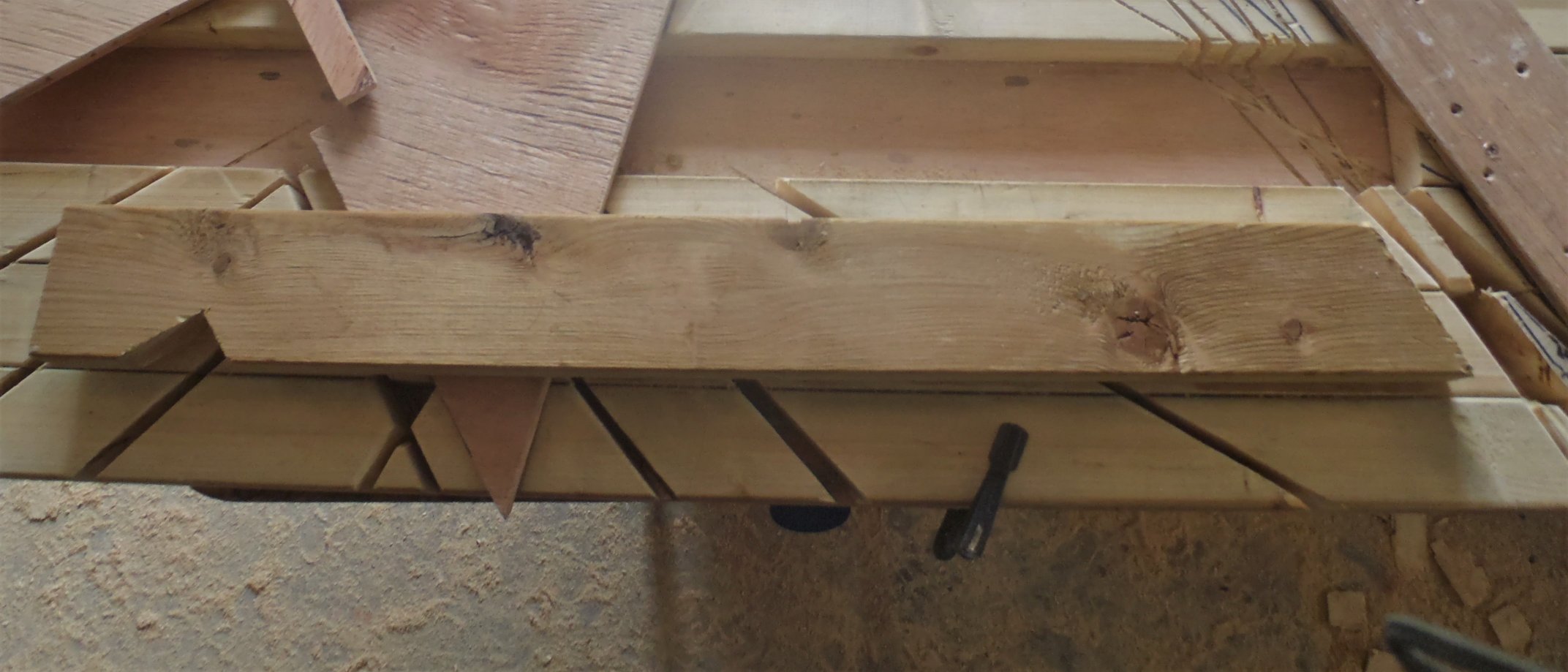
Next we made two diagonal struts that fitted from each corner of the C wall and up to the C Ridge to provide both more anchorage and a surface to nail up the cement panels to form the whole gable wall over the front door and window of the entertainment room.
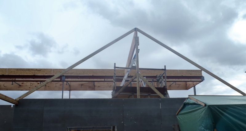
C-Ridge-Wall-end-with-Bracing
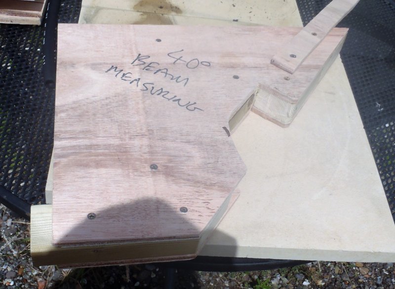
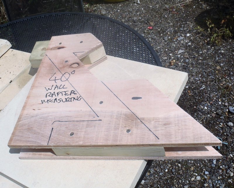
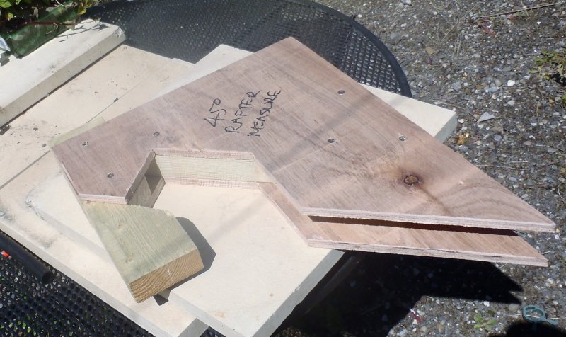
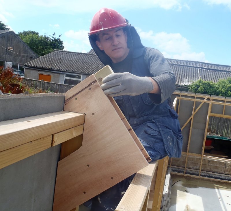
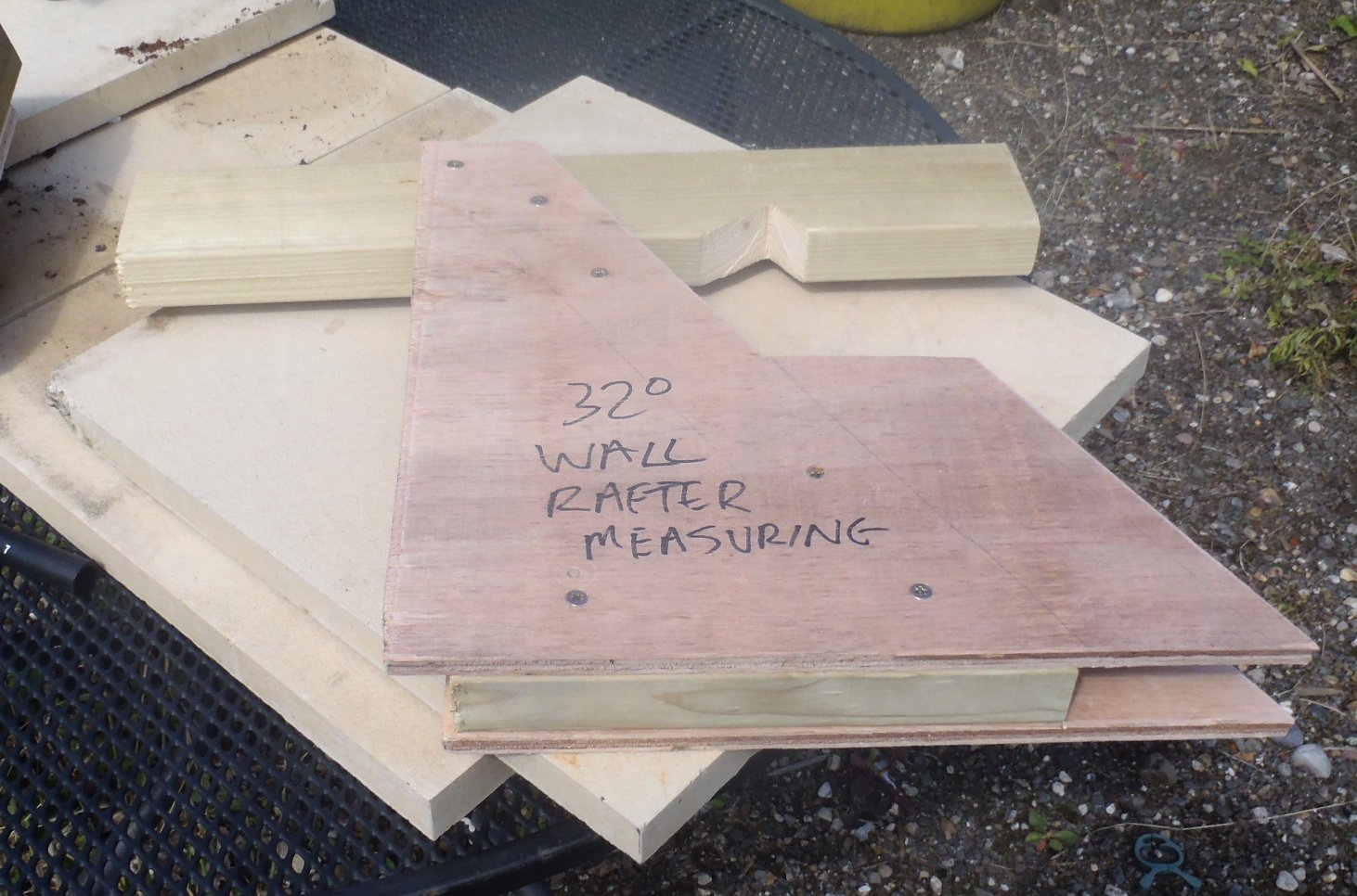
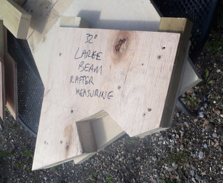
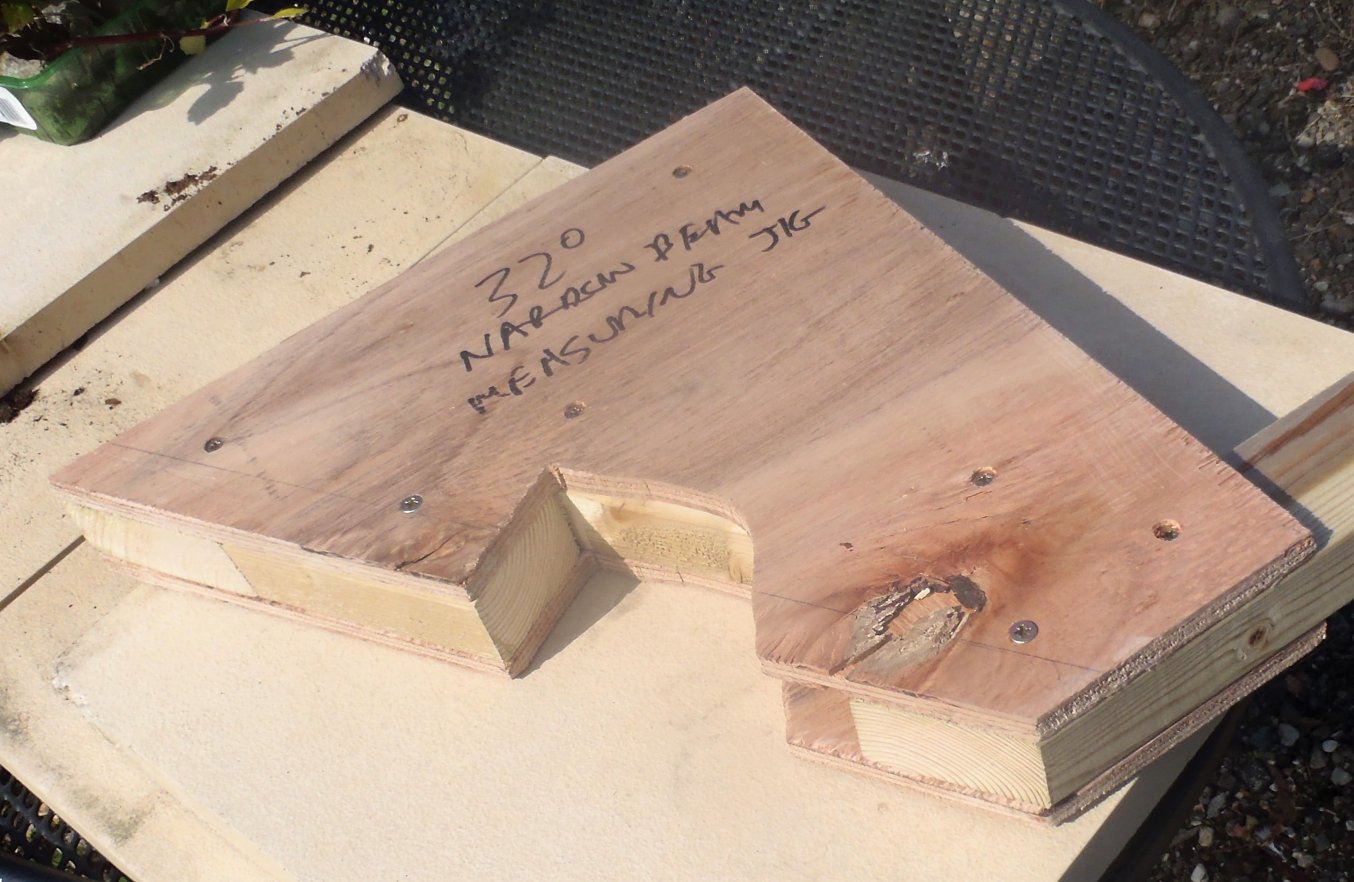
Finally to finish off the day, we measured the diagonal LVL rafters that comes down from the C Ridge at the I-Beam end to the inner corners where the Front extension meets the main wall line. They came out at 5990 mm for the AB corner and 5950 mm for the DE corner which is pretty close to the numbers from our drawings!! So on Saturday, we will make two more LVL beams and slowly build up the skeleton of our roof!!