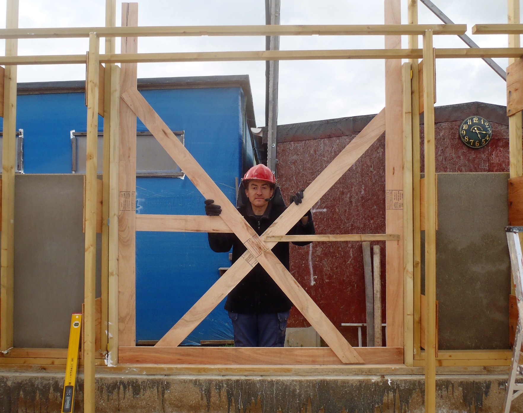
Today, under another glorious and hot sun, we finished off the final Door vertical framework (the Utility Room Back Door), which came out as 1041 mm to 1042 mm wide, in various places from top to bottom, this door will be a single extra wide style to allow better access for bigger items to get into our house.
We then carried on with the next job of putting the Lintels over all the Windows and Doors. We measured and cut to size each opening, the two layers of 89mm CLS timber, glued and nailed together and also nailed down onto the vertical legs. There were 15 openings all to together, and we made sure that all of them were within 1mm to 2mm of being horizontal, putting in solid wooden spacers where necessary to make adjustments.
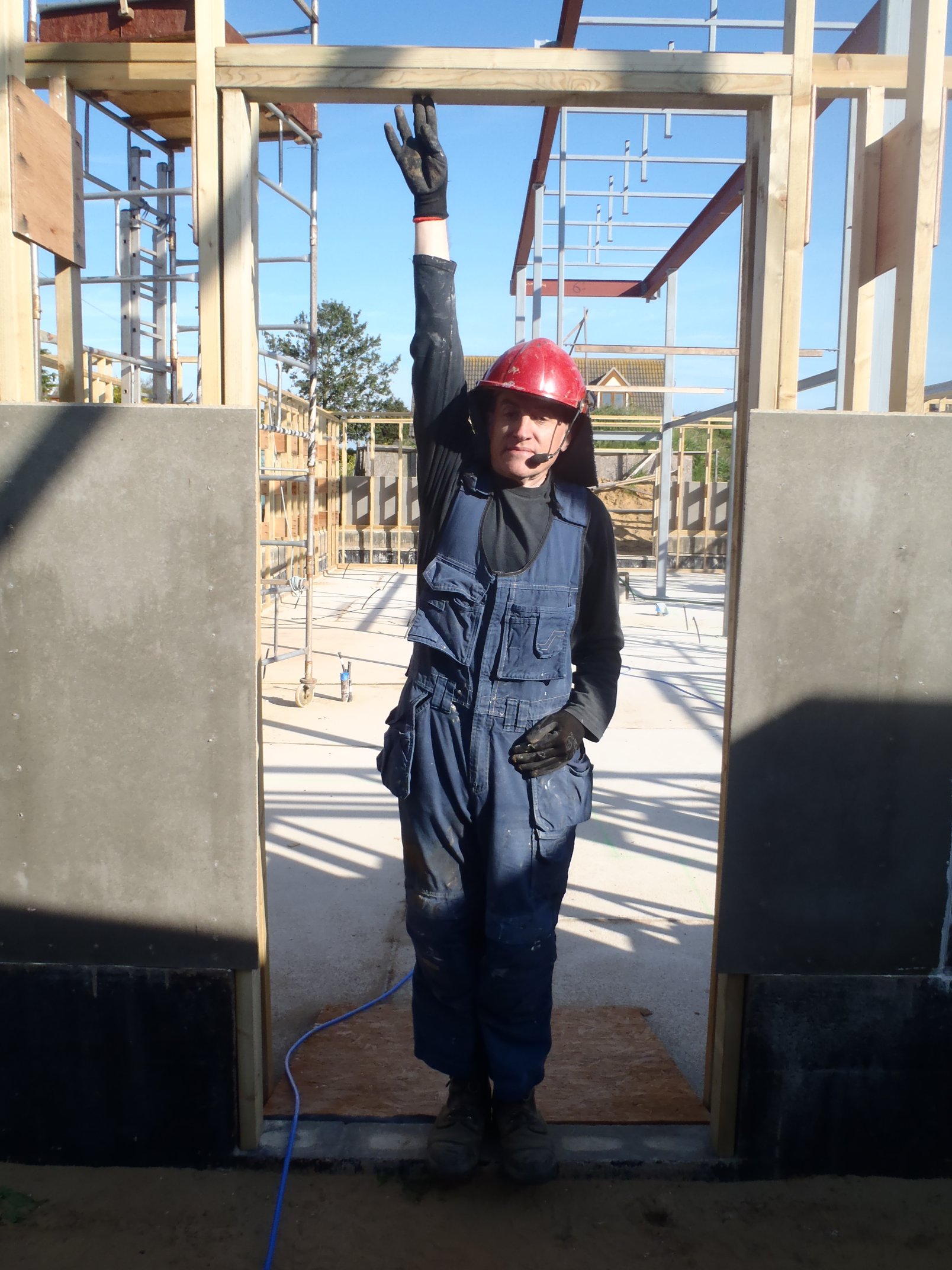
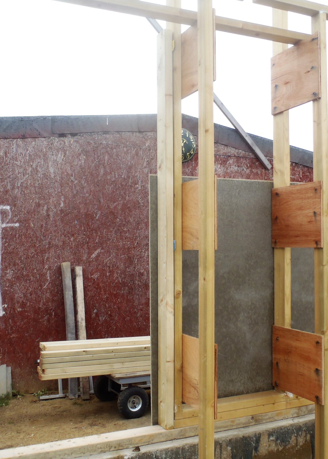
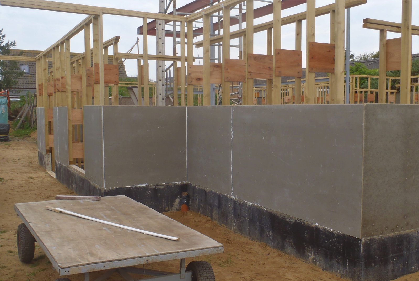
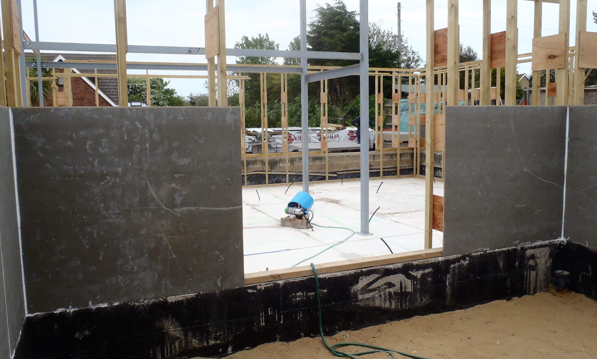
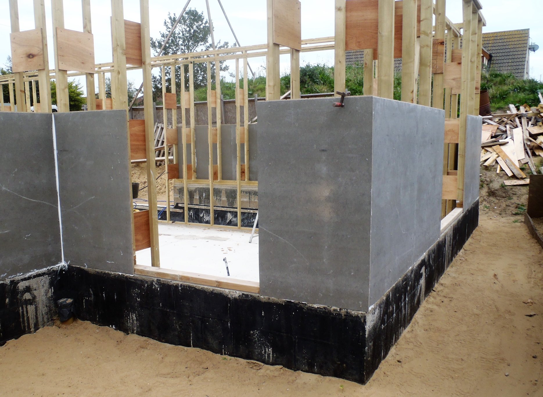
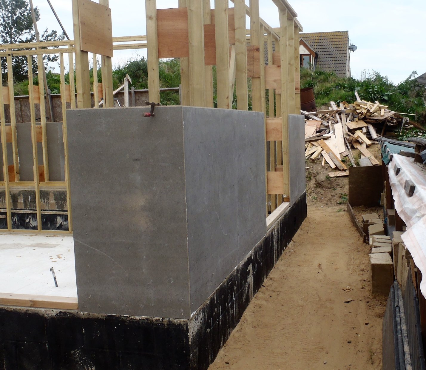
Door-sub-Frame-completed-with-Lintels
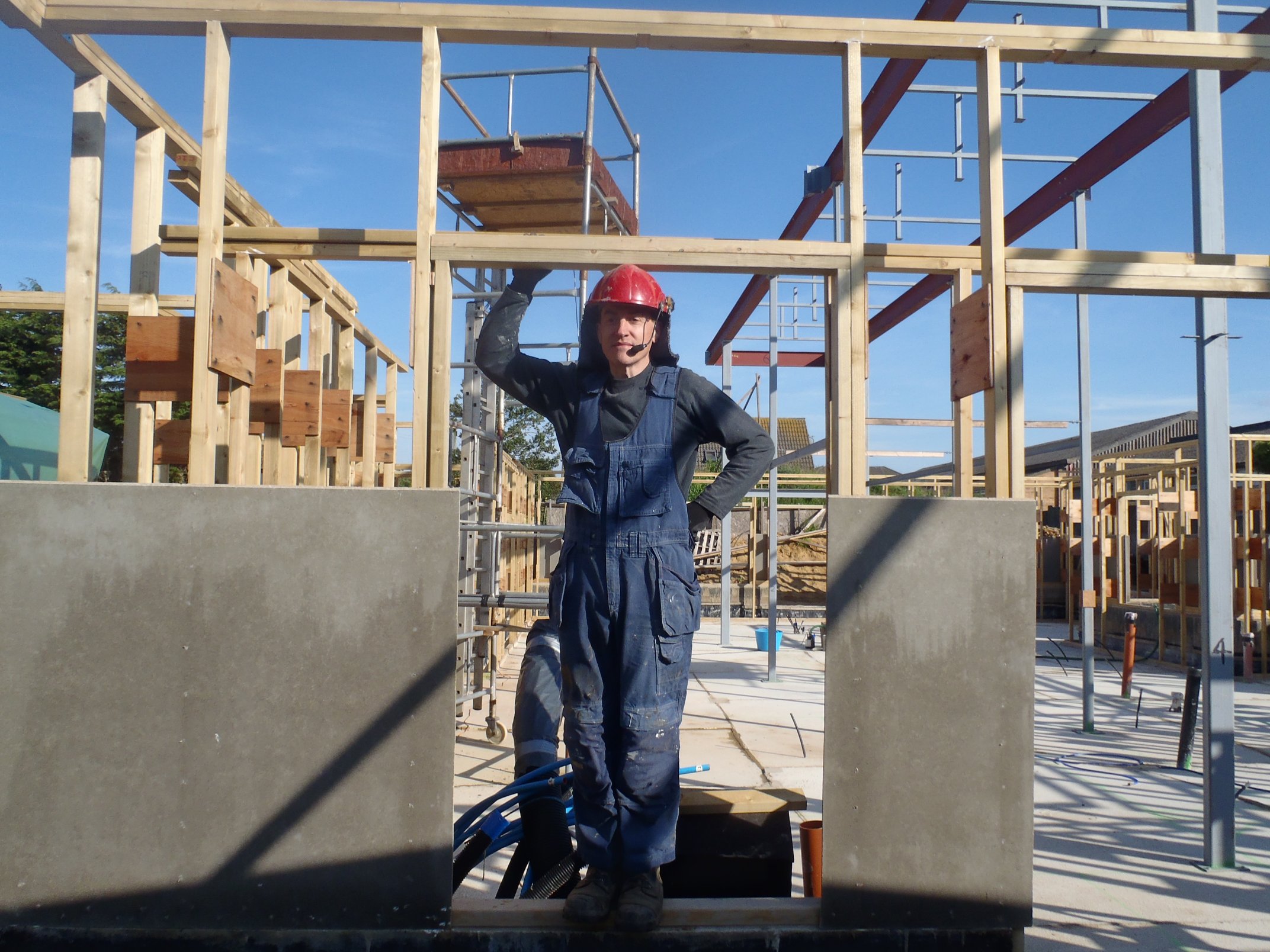
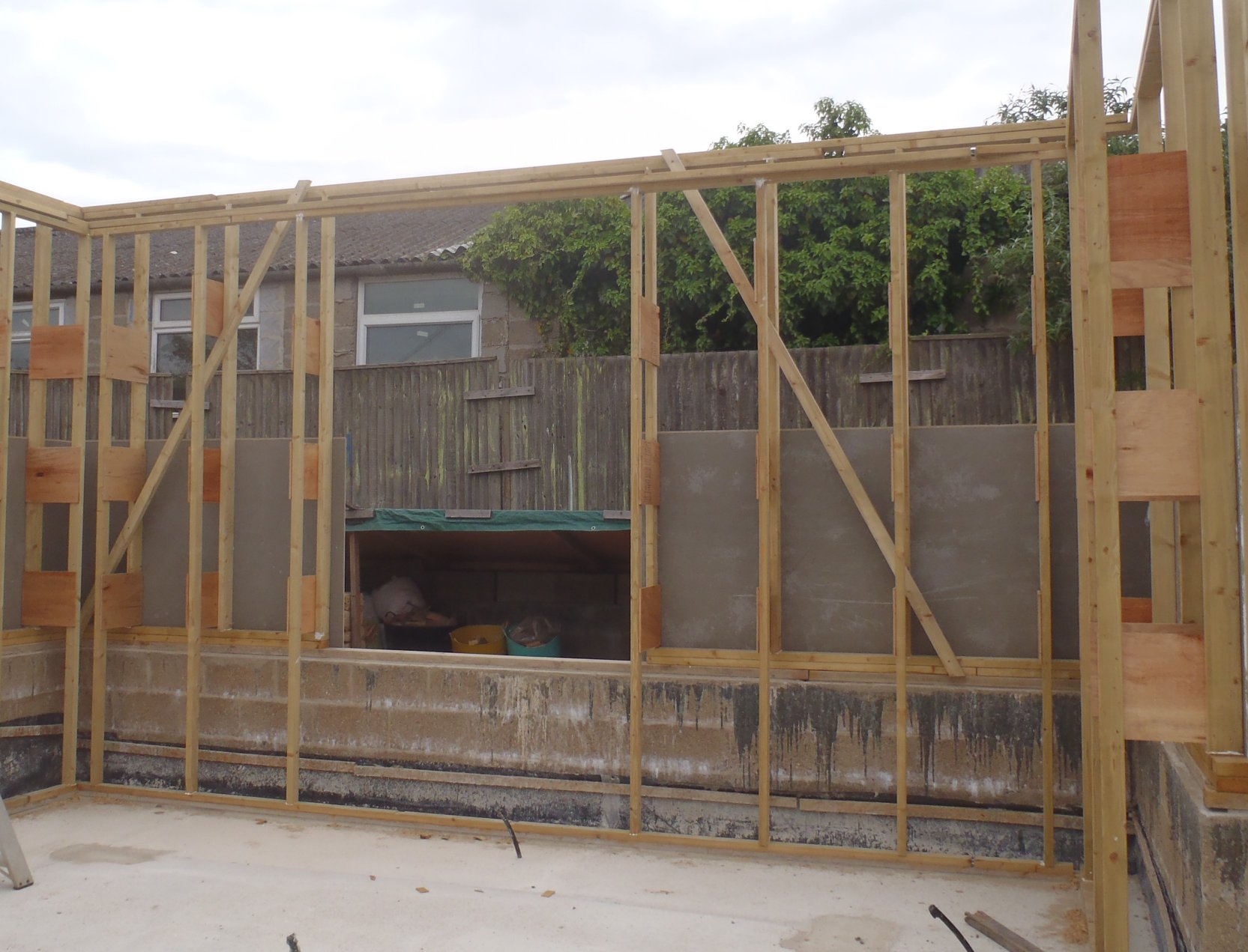
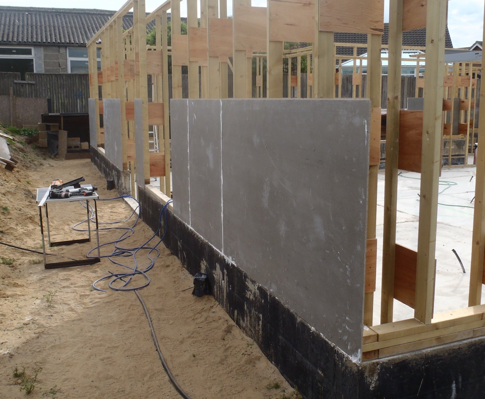
Window-sub-Frame-completed-with-Lintels
Tomorrow, we will first measure the long diagonal rafters that forms the valleys, hips and ridges of our roof, so we can double check against our drawings to know exactly what we need to order from the specialised timber manufacturer, the man-made laminated veneer lumber called LVL. This material is basically lots of thin layers of wood, just like plywood but 200mm thick and can come up to 12metres long – wow! After that piece of survey work, we then carry on with putting in all the vertical short studs that connects the lintels to the Top-Plate, and once this is done, with one or two other little jobs, we then can continue putting up the second line of cement boards!!