Blog

  • Eight Downpipes Installed

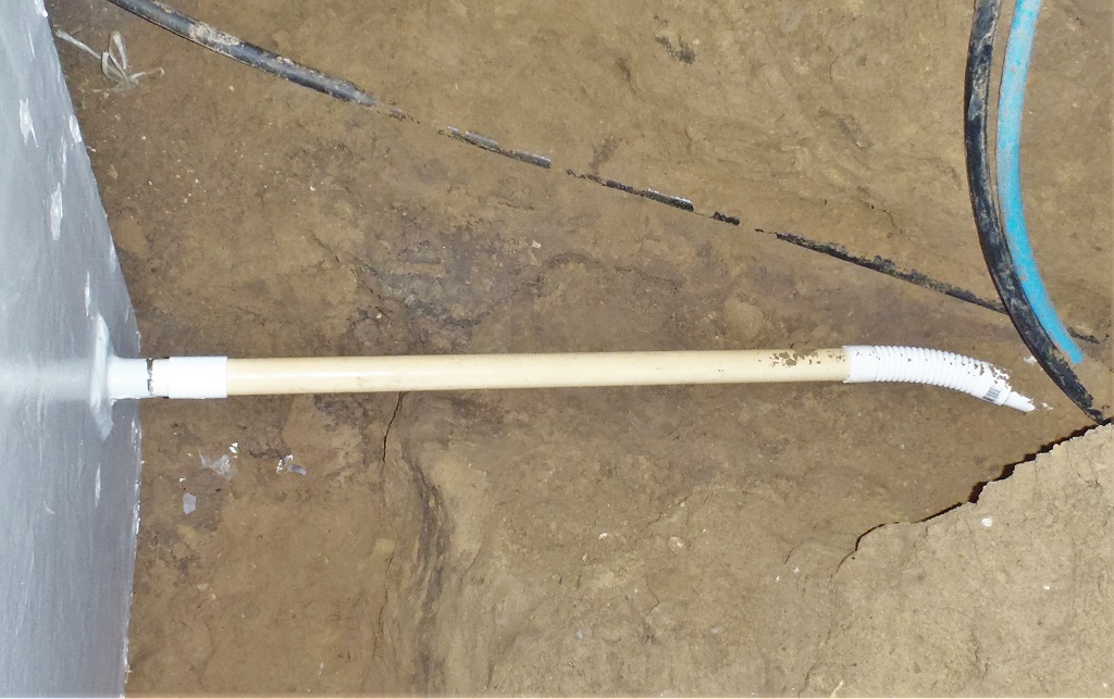
    Whilst planning the slating of the roof we found we needed to attach the guttering to each roof section before anything else because it is the lowest part of the roof and everything else ‘flows’ into it. But if we install the gutter we need somewhere for the water to go so we have to connect the previously installed downpipes to the underground pipe to the rain water filtration unit.

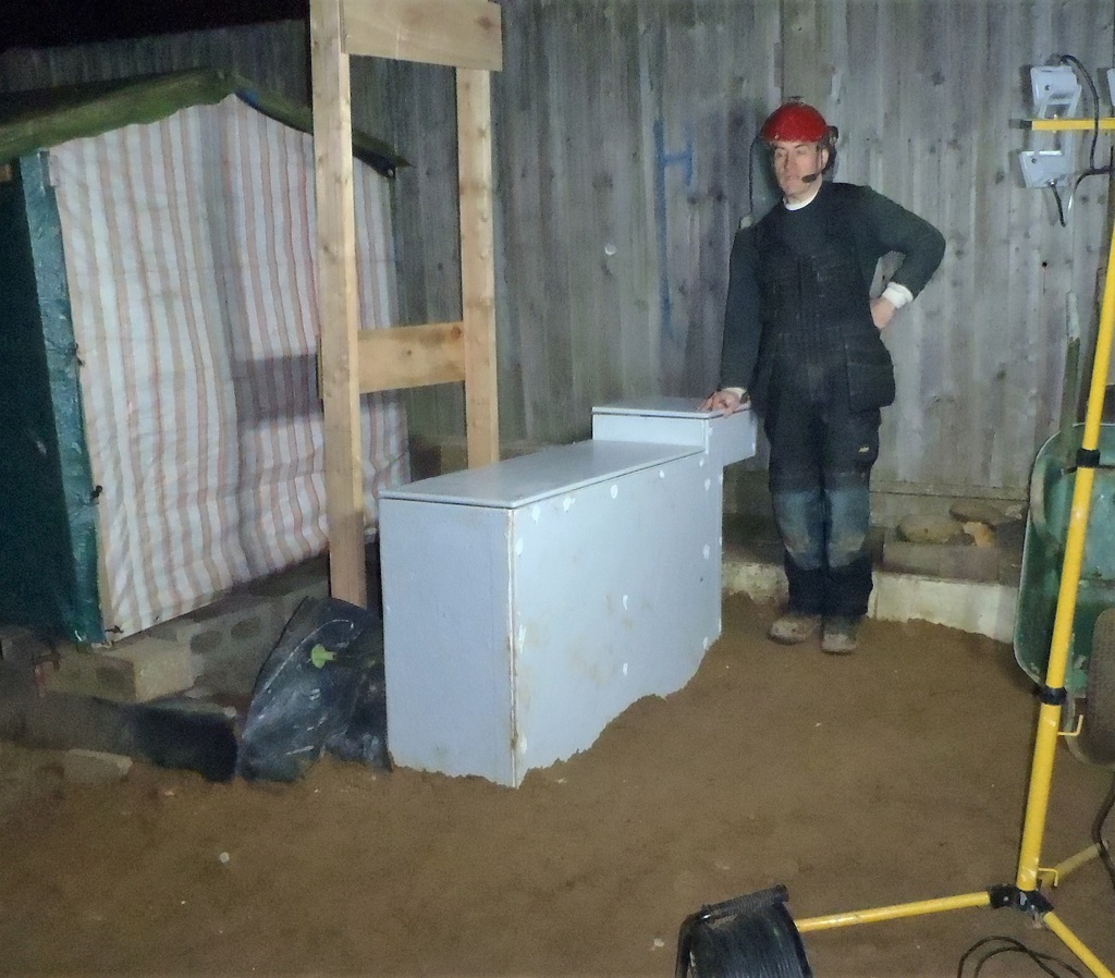
    So yesterday and this morning, we went around putting in the connecting pipes.
    There were eight of them to do around the house, five of them were in corners and the other three were in a middle of a wall section.

    Eight Downpipes Installed

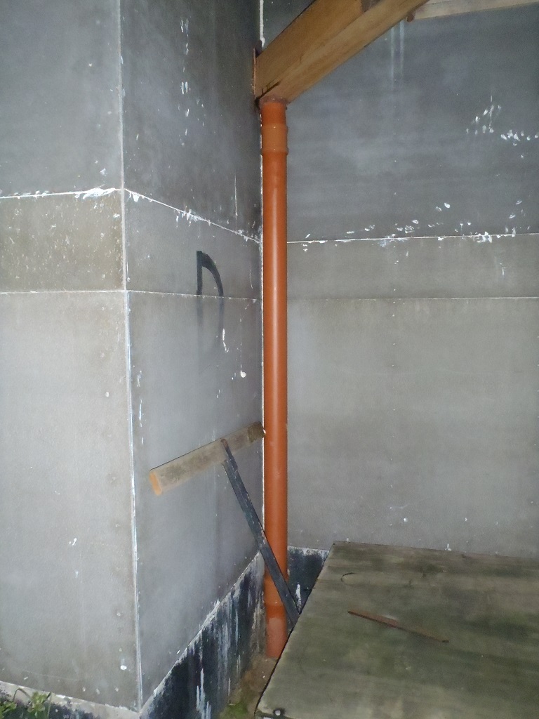
    Downpipe-for-DE-corner

    Eight Downpipes Installed

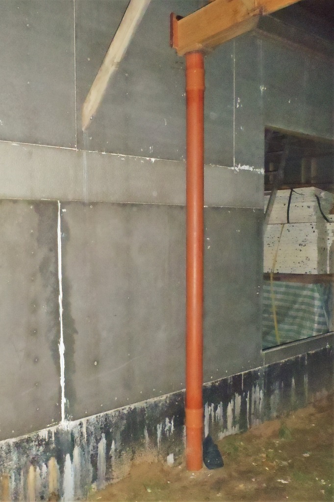
    Downpipe-for-GH-Corner

    Eight Downpipes Installed

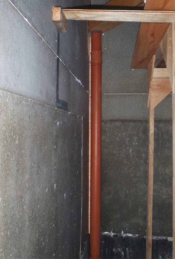
    Downpipe-for-LM-Corner


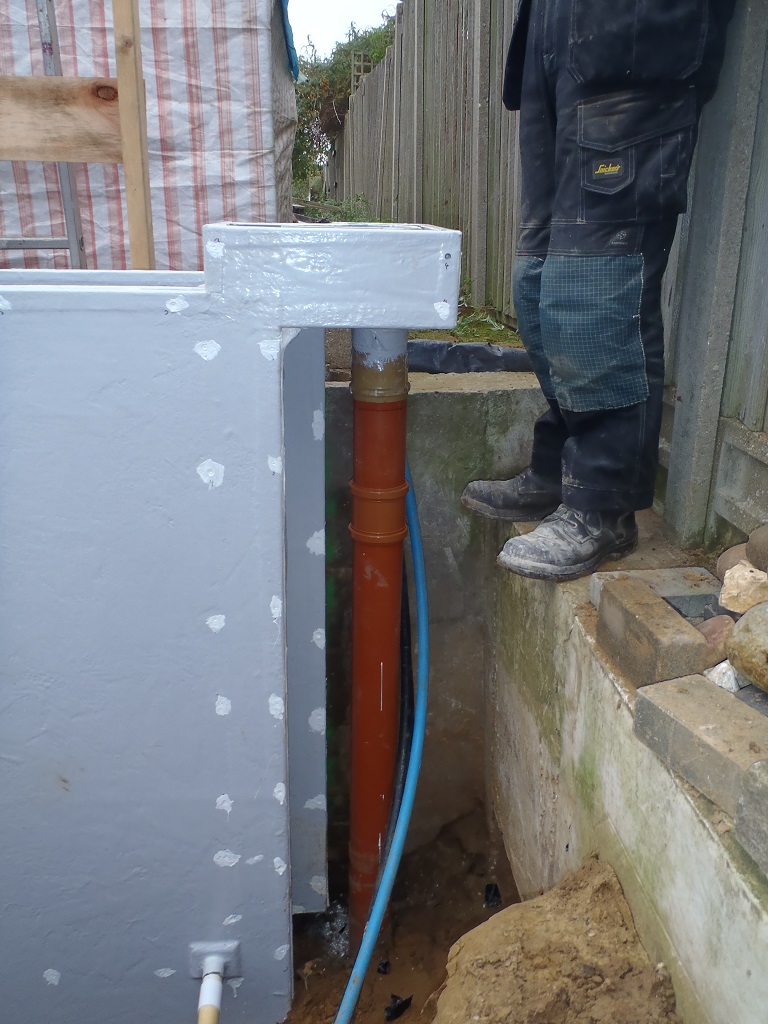
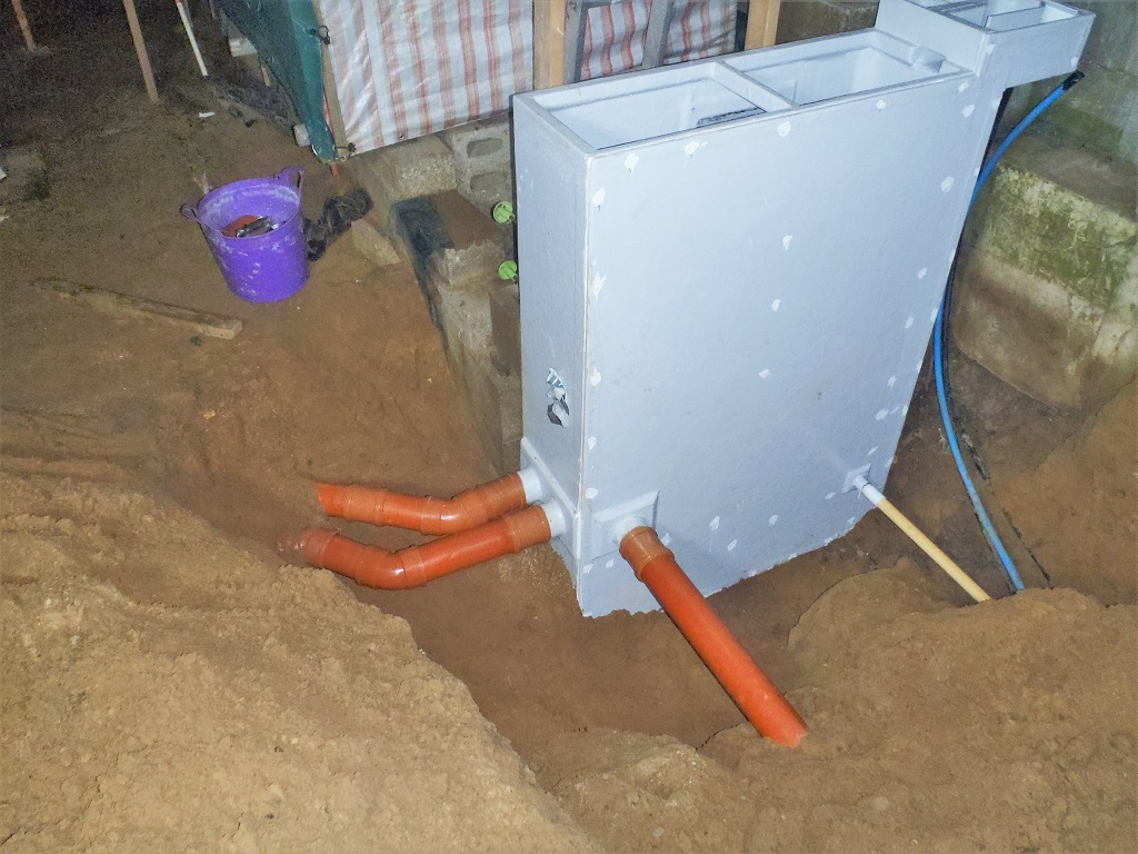
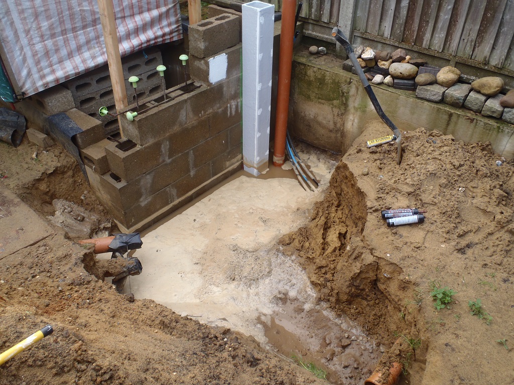
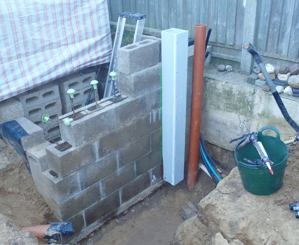
    The only complicated bit of the task to do, was around on the “P” section and the future conservatory. We had originally laid a continuous pipeline running along the whole length of the Great Room, from front to back, but we decided that it would make more sense to remove the section that would go under the conservatory and have the two downpipes to be the starting point of the underground pipelines. So we dug out the existing pipe and replaced the “T” junctions with plain sweep bends instead.
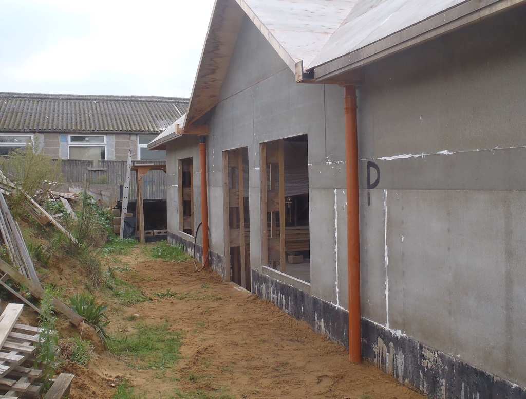
    Eight Downpipes Installed

    Downpipes-on-P


    Now we are ready! So as we complete each section of the roof the rain running off the roof will be collected and dealt with immediately.

  • Lift Shaft Installed and All Working

    Today, we took the opportunity of the fine sunny but cold weather to take our Lift Shaft outside and install it against the walkway platform running around the back of the building. It was positioned against the start of the “I” section of the roof, mounted on a 8feet by 4feet sheet plywood. We also anchored it up at the top of the nearest leg of the platform to ensure that it won’t get blown over in high winds or topple with heavy loads inside it.

    Lift Shaft Installed and All Working

    Complete-Slate-Lift

    Lift Shaft Installed and All Working

    Lift-at-the-Bottom

    Lift Shaft Installed and All Working

    Lift-at-the-top


    We had to slide the cargo cage up inside the Lift Shaft while it was lying on its back, entering from the bottom. Then push the whole thing upright by lifting at the other end (the top end) and slowly walk it gradually upright. It was also anchored at the bottom to the plywood base sheet too.
    We then hooked up the hoist motor at the top of the shaft using a metal pole and unwound the cable down to the cage. The final job was to mount on a second ramp on the other side of the cage, the side facing the platform walkway so we can trundle our dolly trolleys off. We tested the capabilities of the whole system by first loading several heavy concrete blocks into the cargo cage (about 75kg of load) and ran it up and down several times.
    Then we went to our slate storage area and loaded up one of our dolly trolleys full of slate tiles, we managed to put in two rows of 60 slates. We took that back again using our modified flat-bed trolley and loaded it into the cage. We weighed this and the cage on a bathroom scales and it came to just short of 150kg and the cage being about 40kg itself which leaves about 110kg for the box of slates. This latest load test was handled just fine!
    Lift Shaft Installed and All Working

    Loaded-dolley-in-lift

    That is the basic lifting system all done, mechanically speaking at least, but we have ordered some electrical switches, push buttons, limit switches (to detect the position of the cargo cage) and relays plus a micro-controller (tiny computer) chip to join all these pieces with some logic to achieve a much better system of having the ability to push a button to send it up and automatically stopping at the top, and do the same with another button at the top to send it down again. It will have other safety features like the ramp must be folded up and secured before the lift can start moving.

  • Lift Shaft Built

    Today, we created the Lift Shaft to take our box on wire up and down. It measures 730mm by 760mm (internal measurement of 680mm square, the size of the cargo cage) and it is nearly 5metres (16feet) long, or rather tall when it is standing up.

    Lift Shaft Built

    Lift-cage-in-Shaft

    Lift Shaft Built

    The-16-foot-lift-shaft


    We also created the support framework to hold the metal bar which in turn is holding in place the electric hoist.
    And finally, a little sloping roof installed at the top end and we will wrap some heavy duty plastic to protect the motor, electrical wiring and control boxes from rain water.
    Tomorrow, we will man-handle it outside and rotate it upright on to a flat base to anchor it, slide it against the platform walkway and make any final adjustments including putting on the second ramp at the top.

  • Building a Lift Mechanism to Raise our Slates

    Today, we started building various pieces of equipment to help us lift our Slate tiles up to our working platform. We need a lifting mechanism to raise our dolly trolley load of slates so we created a cage measuring 2feet square by 4feet tall, with castor wheels in each corner, both at the bottom and the top.

    Building a Lift Mechanism to Raise our Slates

    Slate-lift-cage


    The cage will be connected from the middle point, via a steel wire, to our electric hoist and controlled by several push buttons and the cage will move up and down inside a framework to keep the cage straight and stop it twisting around or jamming up.
    The other task was to adapt our medium sized flatbed trolley so it can transport three of our dolly boxes to and from the crates of slates, including a little ramp that will bridge the gap to the cage in our lift mechanism.
    Building a Lift Mechanism to Raise our Slates

    Small-trolley-modified-to-carry-slate-dollys


    Tomorrow, we will build the lift shaft, all 16feet of it!!

  • Dolly’s Created to help transport our Slates

    After having a major tidy-up in the workshop (to clear away the tools and mess from building our filtration module), we started on making various pieces of equipment to help us in getting the Slates up onto the roof.
    Today, we created four dolly trolleys to help transport a heap of Slate tiles from our storage area alongside the Loke and get them to where we would be currently working on the roof. They are made out of 18mm OSB board, each dolly is 425mm wide by 400mm in the other dimension and 240mm high, big enough to allow us to pack about 150 slates, in two rows of 75, held vertically (They will weigh up to 150 Kg or 330 lbs i.e 23 stone!).

    Dolly's Created to help transport our Slates

    Slate-dolleys-1

    Dolly's Created to help transport our Slates

    Slate-dolleys-2


    We put on nine little office chair type of castor wheels on each and we tested them by crouching down in the box and get pushed along the floor!
    These will go onto a vertical lift mechanism to take each one up to the walk-way platform, we will design and make the lift next week.

  • Finished The Filtration Module and Now Fully Buried!

    We finished off connecting the last large drain pipe to the Filtration Module, this being the final last resort overflow connection to the soak-away unit.

    Finished The Filtration Module and Now Fully Buried!

    Filter-overflow-connected-to-soakaway


    Then the next job was to climb inside and apply extra sealant around the clean water section and its joints. It was a tight squeeze but we managed it! Finally, we vacuumed out the slightly dirty water in the bottom of the cabinet to reduce the amount of grit and dirt to avoid fouling up our water pump.
    We spent the remaining of the day shovelling all the sandy soil back in and around the cabinet and piled the excess up around it so it can settle down over time.
    The last task was to get the lids installed, using stainless steel threaded rods, glued and screwed in various places around the rim and clearance holes in the lid themselves.
    Finished The Filtration Module and Now Fully Buried!

    Rainwater-Filter-Finished


    The filters and baffles were lowered down inside the module and everything is now ready for the next rain shower, at least off the garage roof, but we can now connect up each section of the guttering (as we complete the slate tiling) and any water will be drained and properly filtered to our water storage tank.

  • Filtration Unit Connected to Pipelines

    Today, the job was to connect the three rainwater inlet pipelines (from our two roofs) and the output pipe to the Filtration module. But first, a leak test was performed. Sprinkling water (from our garden hose) on to the wall above the seals, we noticed that there were a couple of leaks along the bottom edge. After carefully scraping away the sand and gravel and cleaning the joint, more white sealant was applied and forced it into the joint. All the edges was done to ensure that we don’t have another leak.
    Next was connecting the rainwater pipeline coming from the garage which needed a simple right angled turn and head straight into the cabinet. Next was the white pipe (this is the clean water after filtration and supplying our underground tank) but we discovered that we needed a 30° turn to make it head perpendicular into the cabinet and no one sold this angle for 40mm diameter pipes (they had 90° and 45° and straight) but nothing else. so we had to go out and buy a flexible small length of pipe. We glued together the required pieces to form the pipeline to the underground storage tank (under the garage).

    Filtration Unit Connected to Pipelines

    Output-to-the-rain-tank-with-bendy-joint


    Finally, the last two rainwater pipelines (from the main house) were connected to the side of the cabinet.
    Filtration Unit Connected to Pipelines

    Filter-connected


    All these joints had to have a slip type of connector which allowed the whole straight connector to slide almost fully onto the pipe, move or rotate the assembled pipeline into place and push the slip connector over the both pieces.
    The last job tomorrow is to do further water leakage tests and then connect the soak-away pipeline to the back of the cabinet to takeaway overflowing water (on those very rare occasions of a very heavy thunderstorm).

  • Filtration Module Got Installed!

    Today, we took the opportunity of a very nice sunny day and that the hole was reasonably dry, to tackle the job of installing and burying our new Rainwater Filtration Module, at the end of the swimming lane. We have had to wait for a few days whilst the rain drained out of the hole (The roof of the garage drains into the hole at the moment – it will connect to the filter soon)

    Filtration Module Got Installed!

    Lots-of-water-in-Filter-hole


    We started by digging out the hole of the excess material that had slipped in during the rain we had last week and got a wheel barrow load of gravel and sand mixture to provide a good and firm surface. We used our laser site level to make sure the bottom of the hole was set to 1metre below ground level.
    Then we built a ramp come platform (made from three 4.8metres 2inch by 4inch planks screwed together using lots of pieces of plywood) and placed it across our hole (the far end supported on the mass wall against the fence and the other end packed on to the dirt pile), ready to take our 140kg cabinet!
    We laid the module on the trolley, put on some extra temporary support arms at the top of the cabinet (for connecting lifting straps to the winch motor) and carefully rolled it out of our workshop and around to our ramp.
    Filtration Module Got Installed!

    Filter-on-its-way


    After a struggle to get it upright, and then sliding it along the ramp and then trying rope but finally settling on nylon straps to lift it clear. We pulled the ramp away and lowered the whole cabinet down into our hole. After some fiddling around with the straps and the supporting arm plus also tidying up the gravel surface again, we got the thing landed solidly into place at last!
    It was getting dark by this time so we got out our flood lights and carried on with drilling the seven fixing holes into the concrete blocks of the swimming lane’s wall and screwing concrete bolts into the back of the cabinet and then covering up the metal work with more polyester resin.
    The last job was to secure the vertical side “lid” to enclose and seal the joint with plenty of PU sealant and a couple dozens of screws.
    Filtration Module Got Installed!

    Filter-installed

    It was pitch black and tomorrow, we will finish the task of connecting the various pipelines to the new filtration module, including doing a leak test! Phew what a long day it was today!!

  • Another Week On Filtration Module and All Done At Last!

    This report is a summary of our week’s worth of work we did on our rainwater Filtration Module. Most of the time was spent on creating the two filter units and two baffles. The flat one had the wire mesh welded onto a heavy metal framework and then coated in several layers of resin to prevent rusting. The second filter unit is a square box shaped, made with just more of the same wire mesh and this was also coated in resin too. Our geotextile material was delivered and we cut and shaped the material into each of these two filters. The flat one had extra padding tied onto the metal edge to provide a soft conforming interface and reduce any leaks. The outer layer was then stitched into place with fishing line.

    Another Week On Filtration Module and All Done At Last!

    Clean-water-filter-support-ready-for-filter

    Another Week On Filtration Module and All Done At Last!

    Clean-water-filter-finished


    The box filter had the same cloth material wrapped up the inside and folded into the flange edging and coated in several layers of resin to reinforce it and lock the cloth into place.

    Then we made two baffles, which are like flat tea tray like objects, about 400mm (15inches) wide and 580 (22inches) long, with upwards edges approximately 25mm high. We used some more wire mesh and laid two layers of the glass fibre matting (one on the underside of the mesh and the second one inside the tray) and all coated in resin. We had to bend up several tags over the tray so it can support its sibling companion tray on top, and the top tray having water deflectors to help slow down the rainwater rushing into the cabinet.

    Finally, we did some minor adjustments inside the main cabinet, mostly in the area of the clean water filter, near the bottom portion.

    Another job we did this week was the installation of the Return Channel vertical module to the end of the Swimming Lane. It was a lovely day so we took the opportunity to get that done while we remembered it before we tackled the big job of getting the main cabinet installed.

    Another Week On Filtration Module and All Done At Last!

    Swimming-Lane-circulation-column-installed

    Now we just need another moment like this to haul the large heavy module into place.

  • Water Filters Progresses

    Today, we continued with the task of building our two water filters. The long flat one’s frame is now constructed with a heavy thick metal bar around the perimeter and the metal mesh is welded on to it.

    Water Filters Progresses

    Clean-Water-Filter-frame-made-1

    Water Filters Progresses

    Clean-Water-Filter-frame-made-2

    Water Filters Progresses

    Clean-Water-Filter-frame-made-3


    The second filter, the box shaped one, was tidied up, removing excess mesh material and it is now ready for the cloth geotextile fabric to be folded and inserted in.
    Water Filters Progresses

    Dirtywater-Filter-mesh-basket-formed


    Hopefully, tomorrow, we will get our new piece of the geotextile fabric (coming in the post) and we can wrap these two skeleton frameworks and then paint the metalwork in protective resin to stop rusting and also seal and hold the cloth in place.