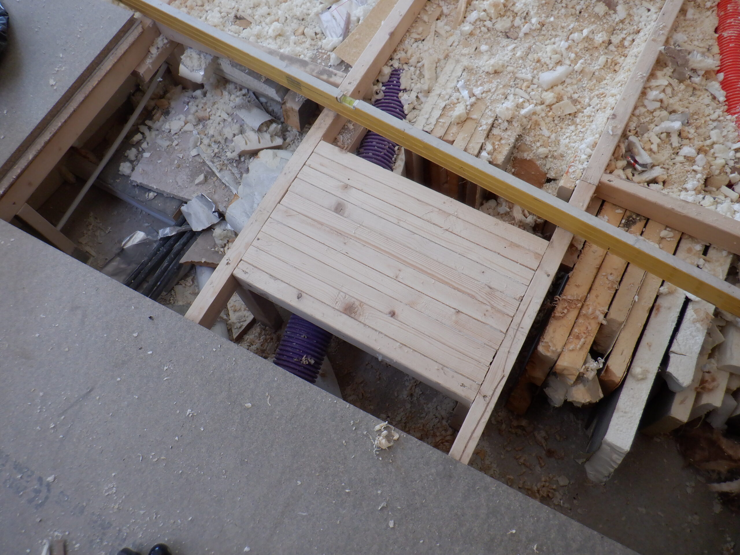
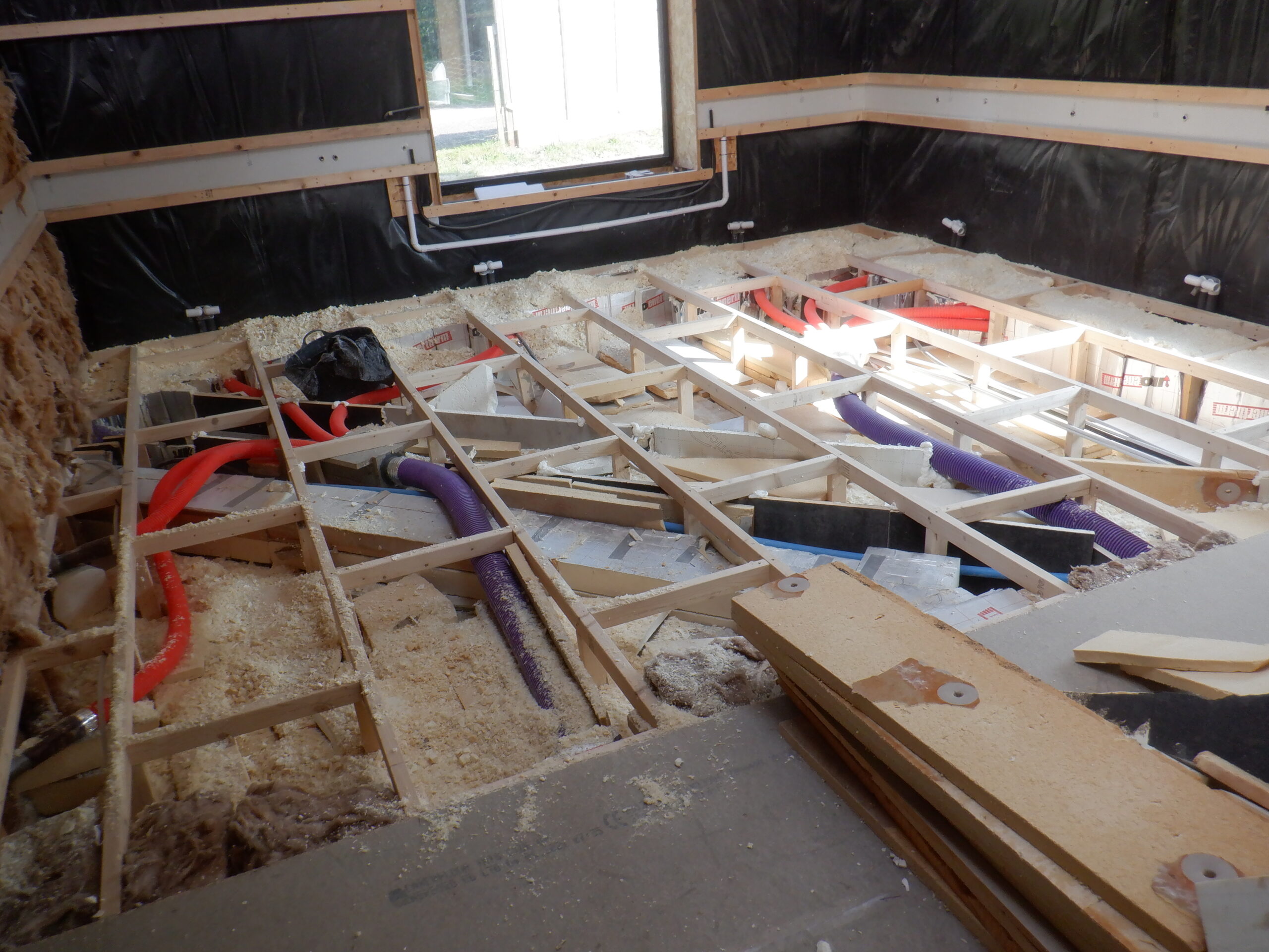
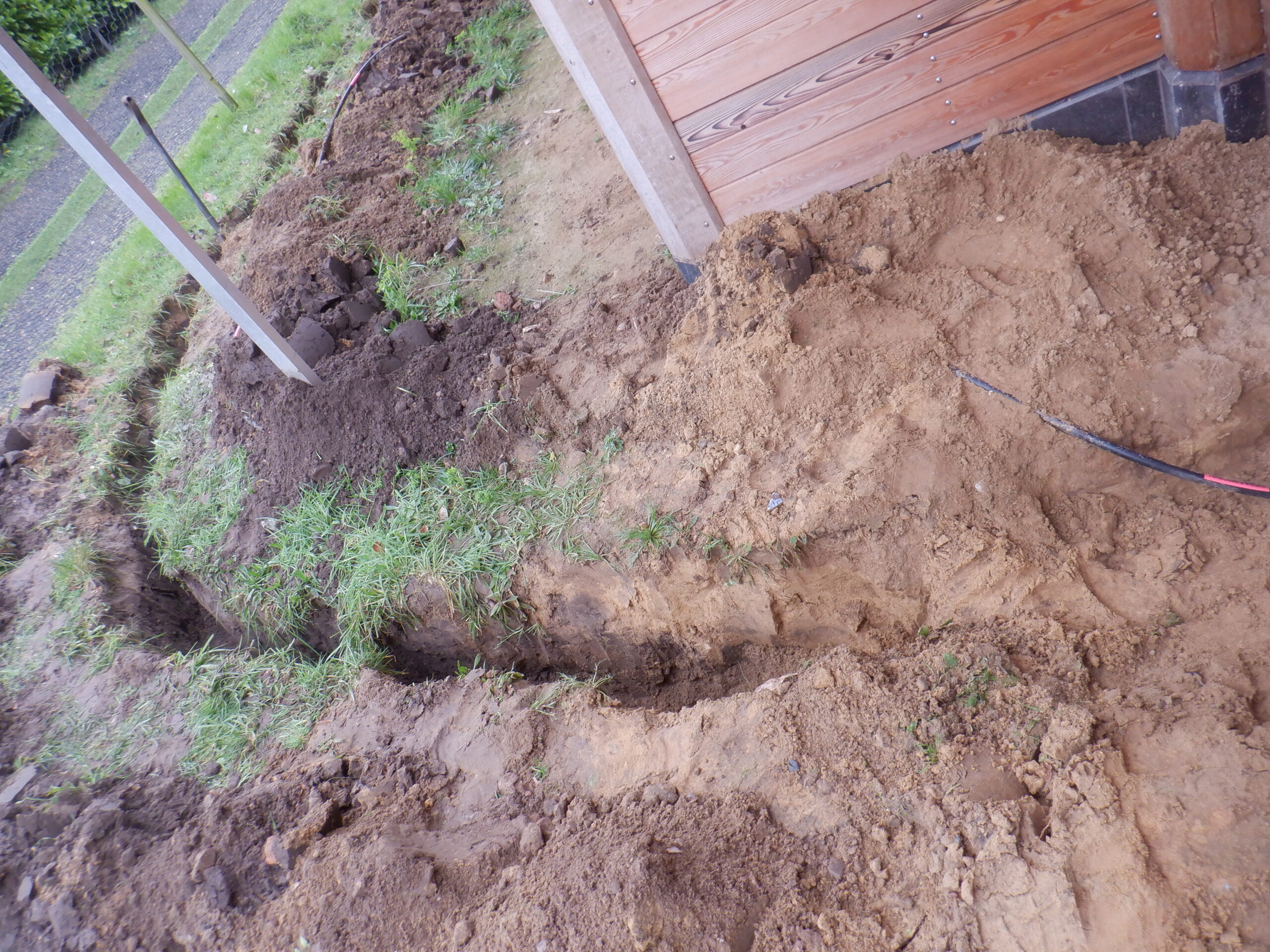
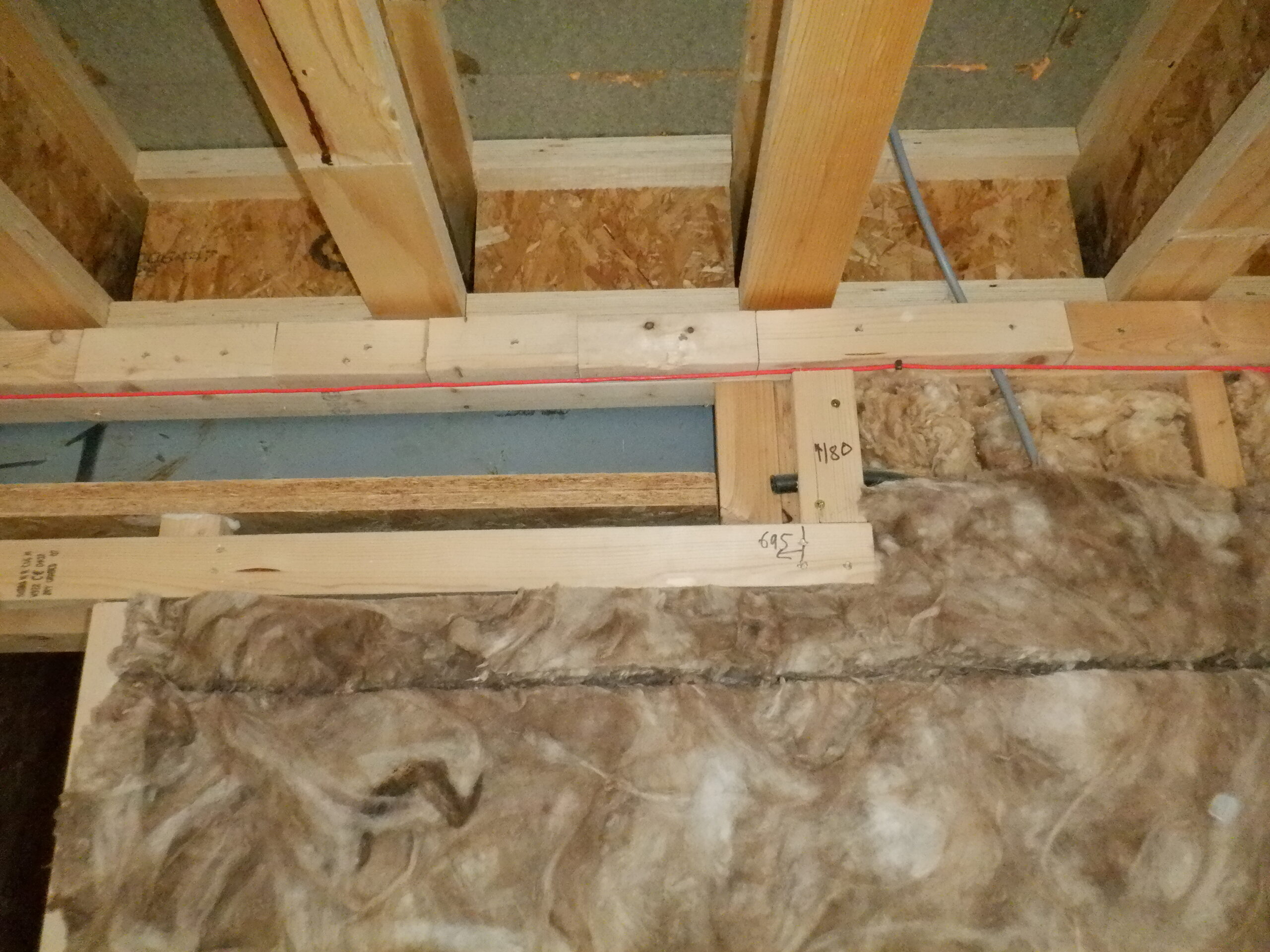
But first we nailed up a complete loop of 63mm CLS timber pieces near ground level that we deliberately left for construction later on, to make it easier to lay down the floorboards. The rail sits the top of the Air Channel which is 150mm high.
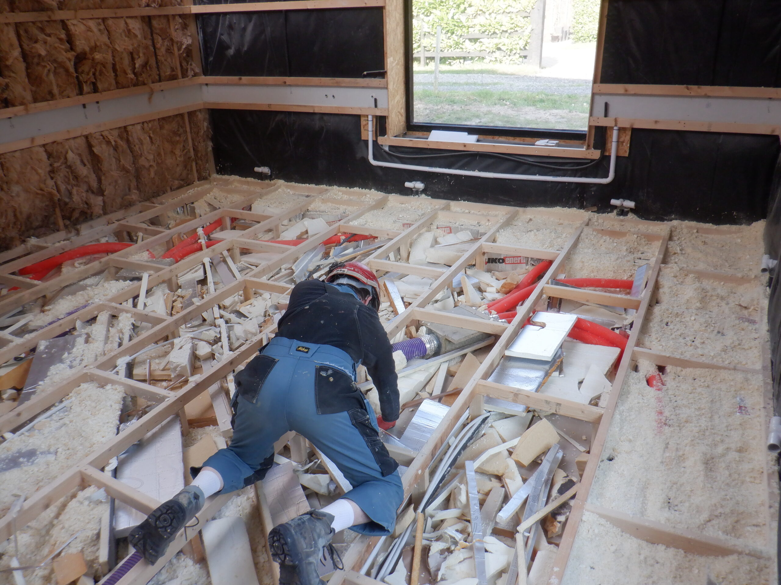
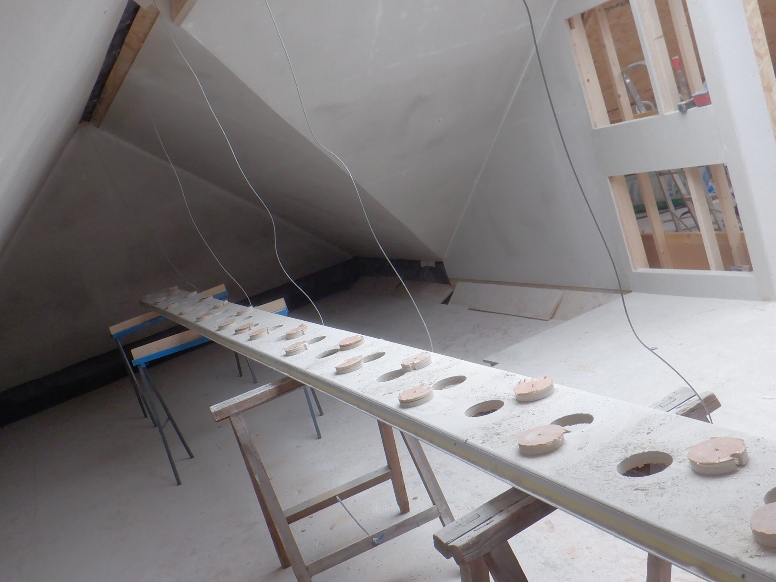
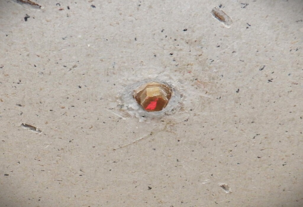
The next task, we noticed that our existing sixteen air distributors needed to be more secured so we went around anchoring them into place so they did not protrude beyond the CLS rails, avoiding being squashed when we put up the OSB boards, or fall backward into the wall cavity. We used little stainless steel screws to lock each plastic unit into place.
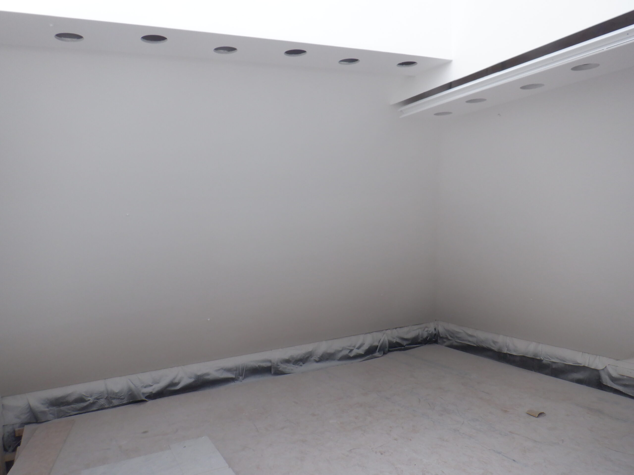
The next job is to put in the Air Channel backing strips, to guide the air around the room and float gently outwards. We use our stock of 6mm MDF strips to go around the entire room but we discovered that we were short so we went out to buy another sheet of MDF material and sliced it up into more 150mm wide strips.
We sealed both the MDF strips along the top and bottom edges and also the Air Distributors themselves so all the air will get sent out into and along the Air Channels and into our Great Room.
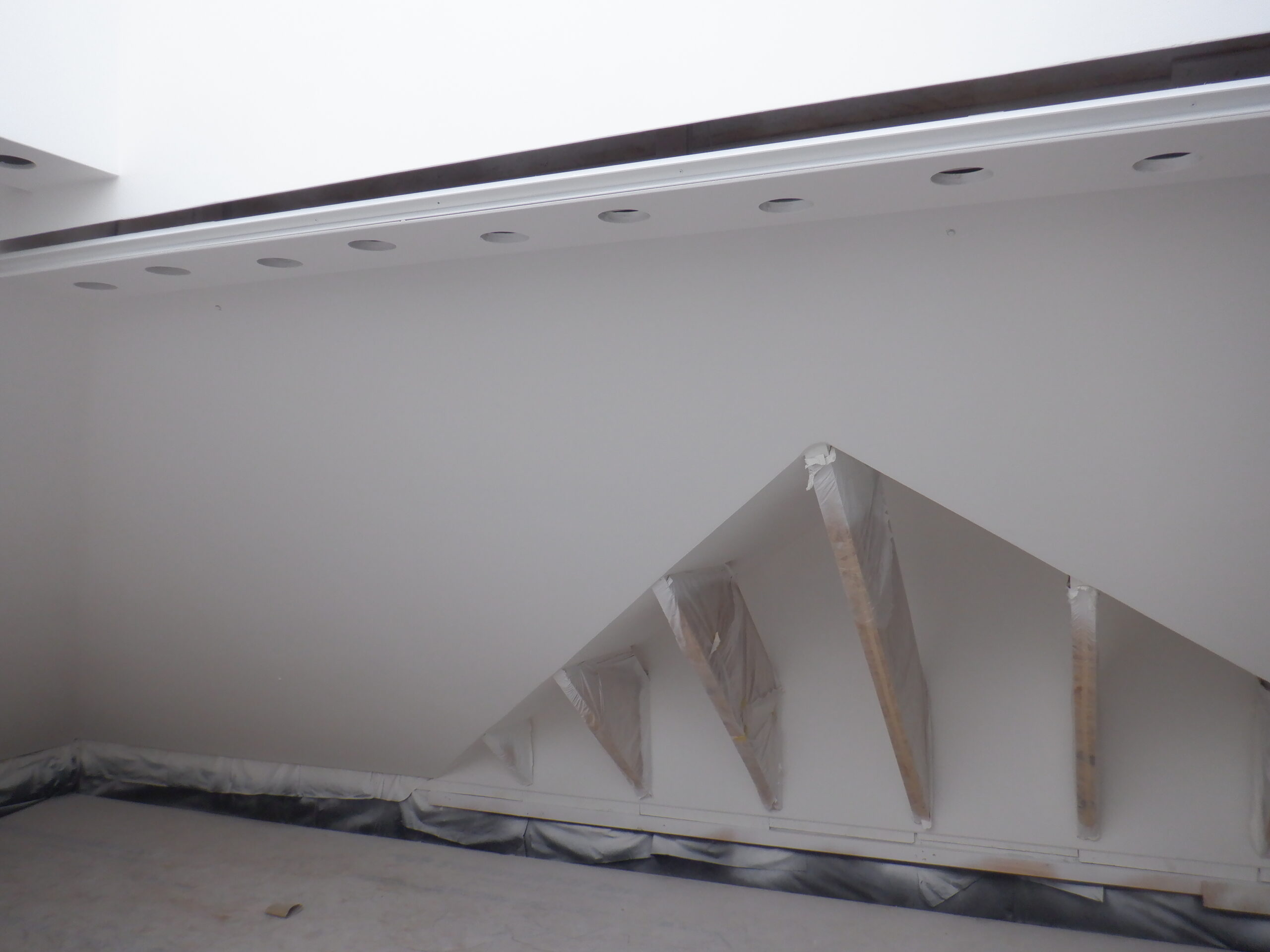
Great room air outlets
We also painted the lower 50mm black so no one will be able to sneak a look along the carpets and perhaps notice something pale lurking inside the wall!
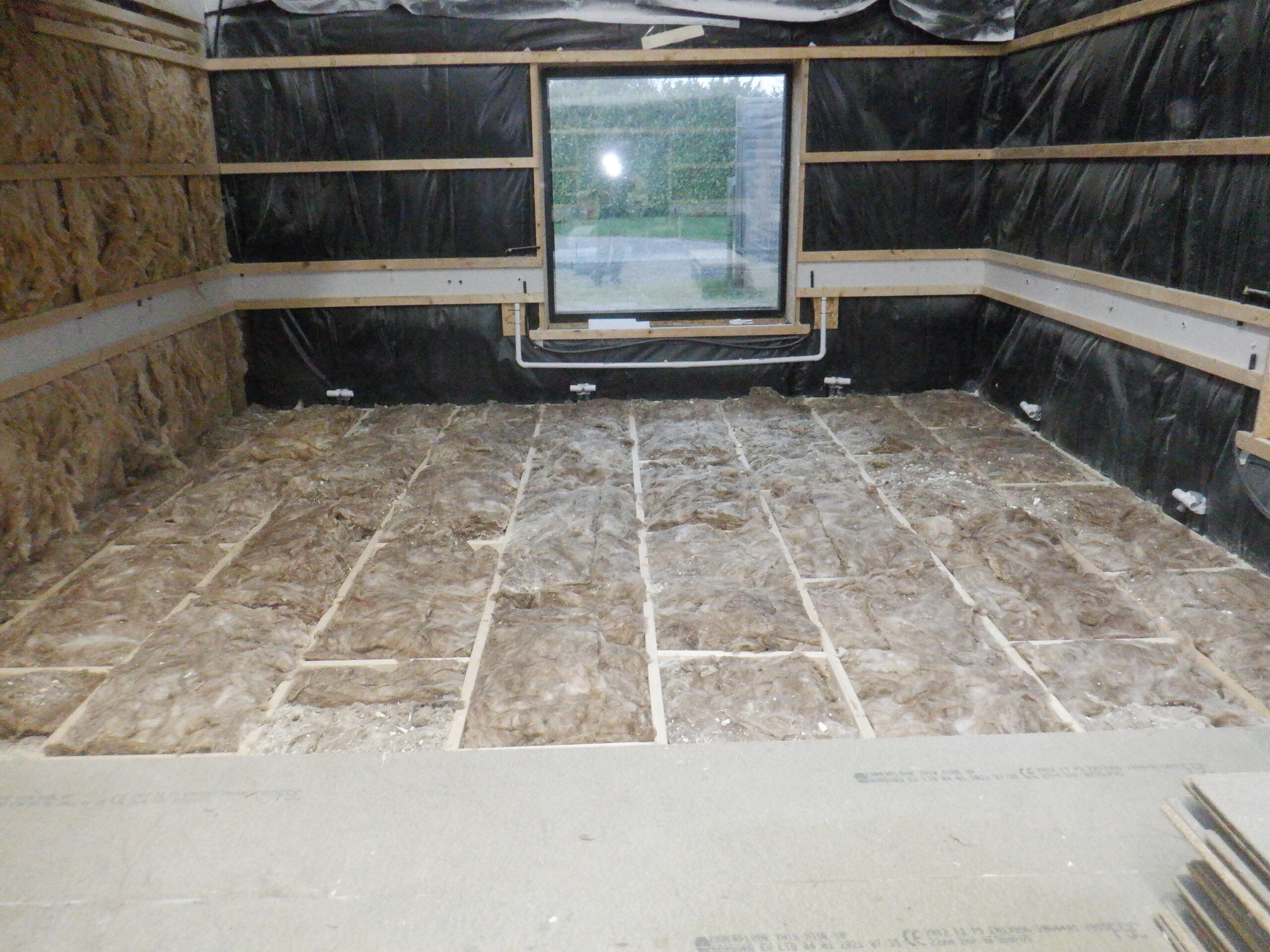
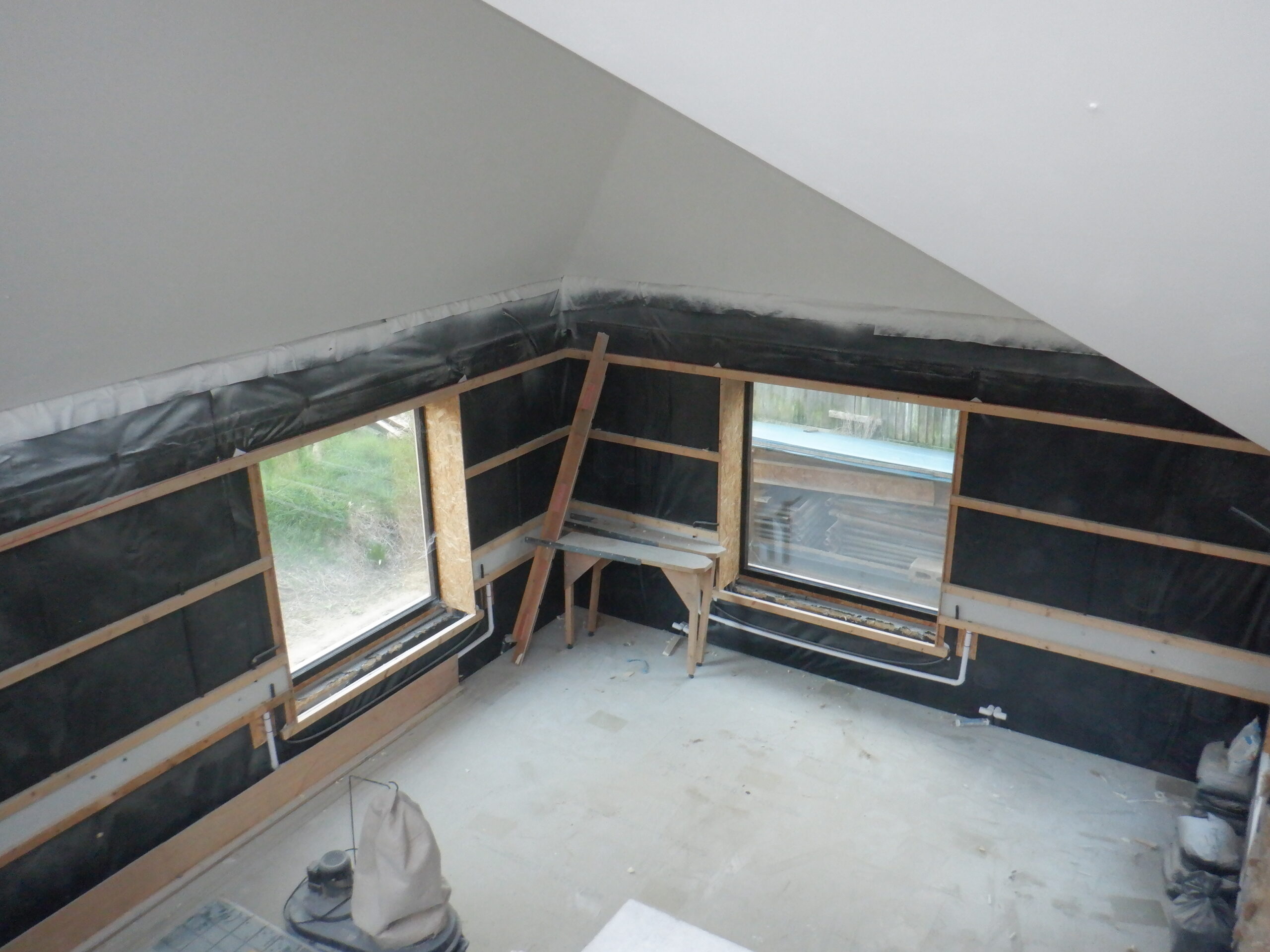
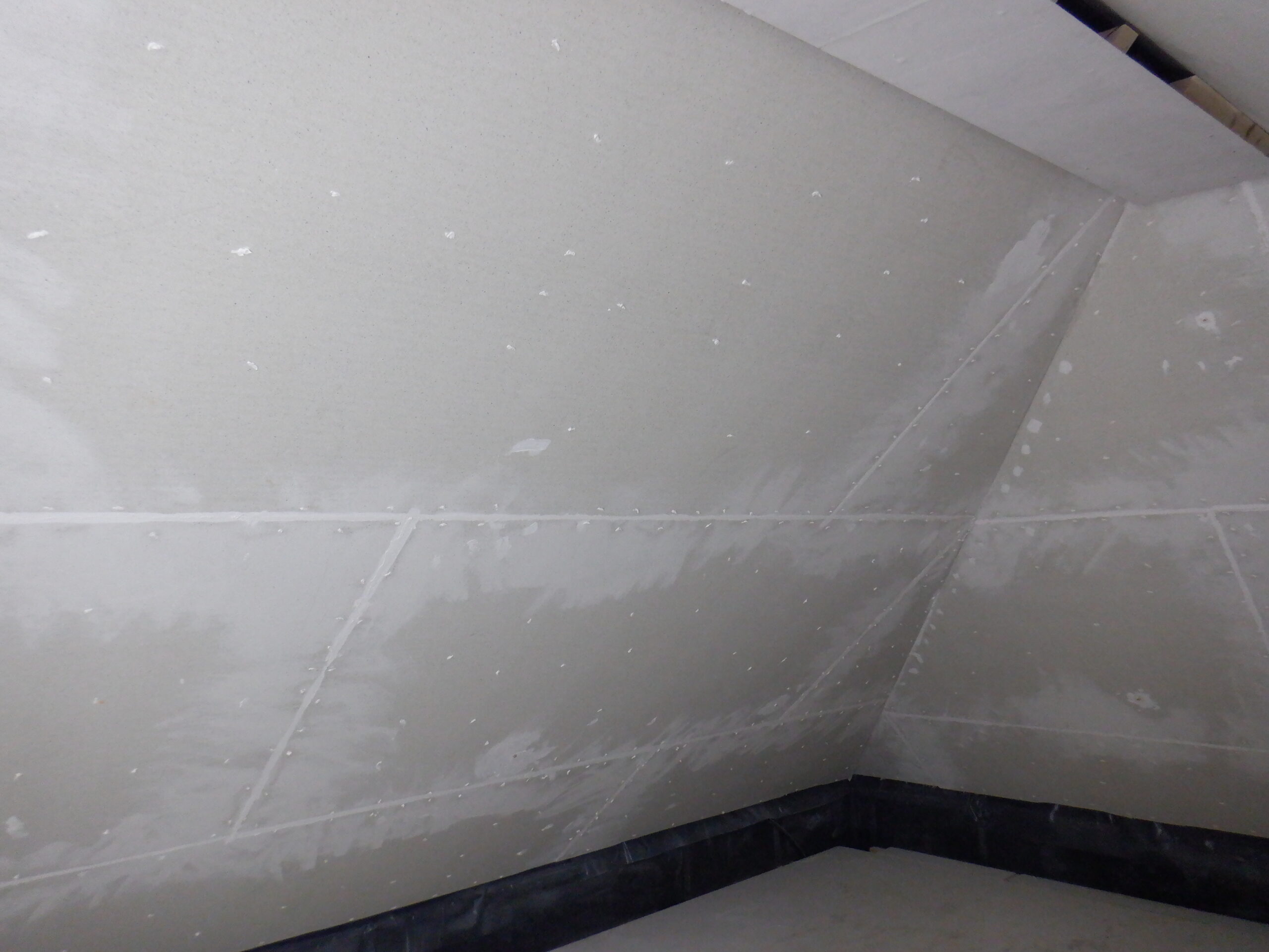
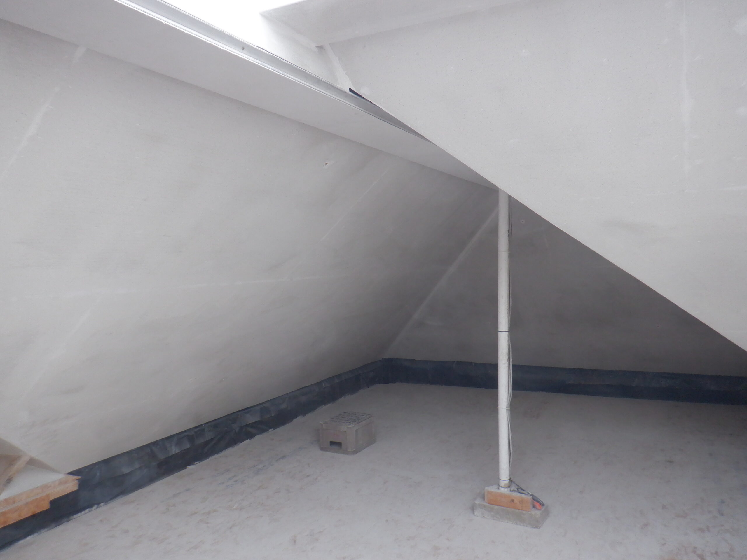
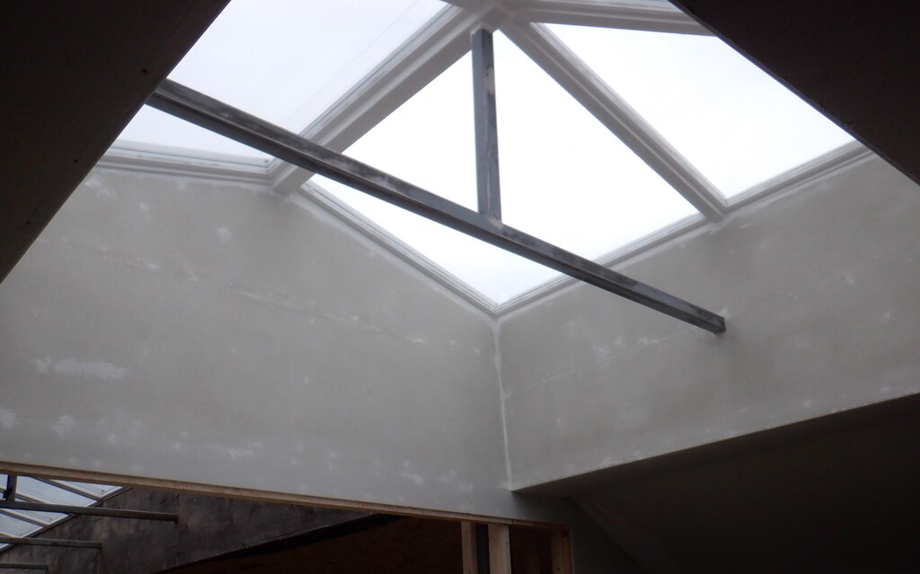
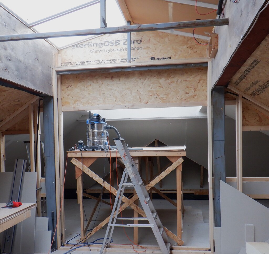
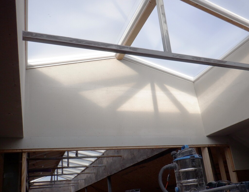
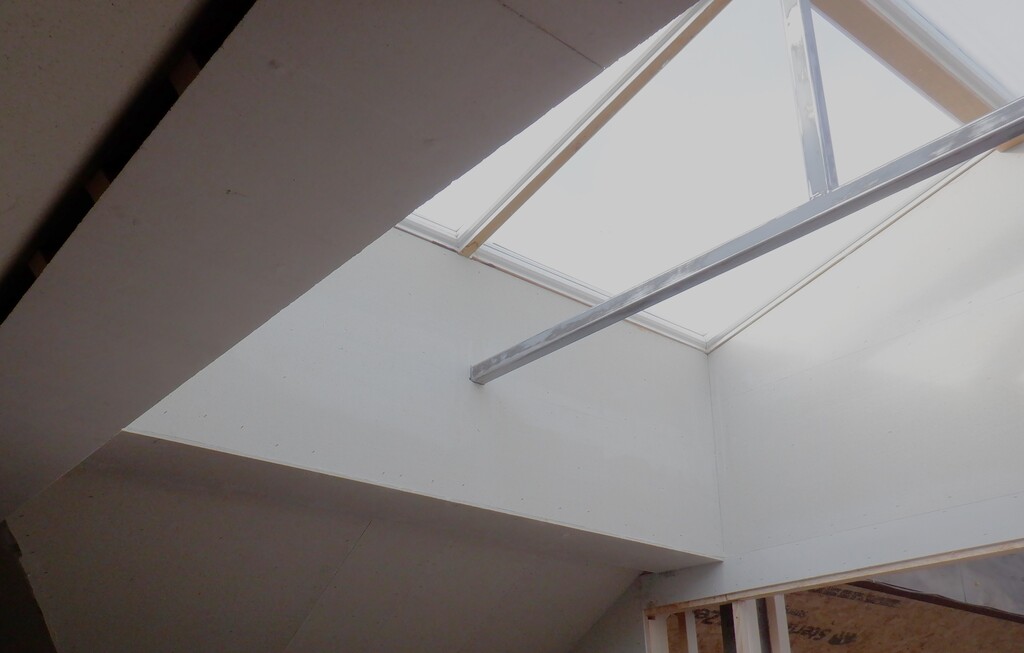
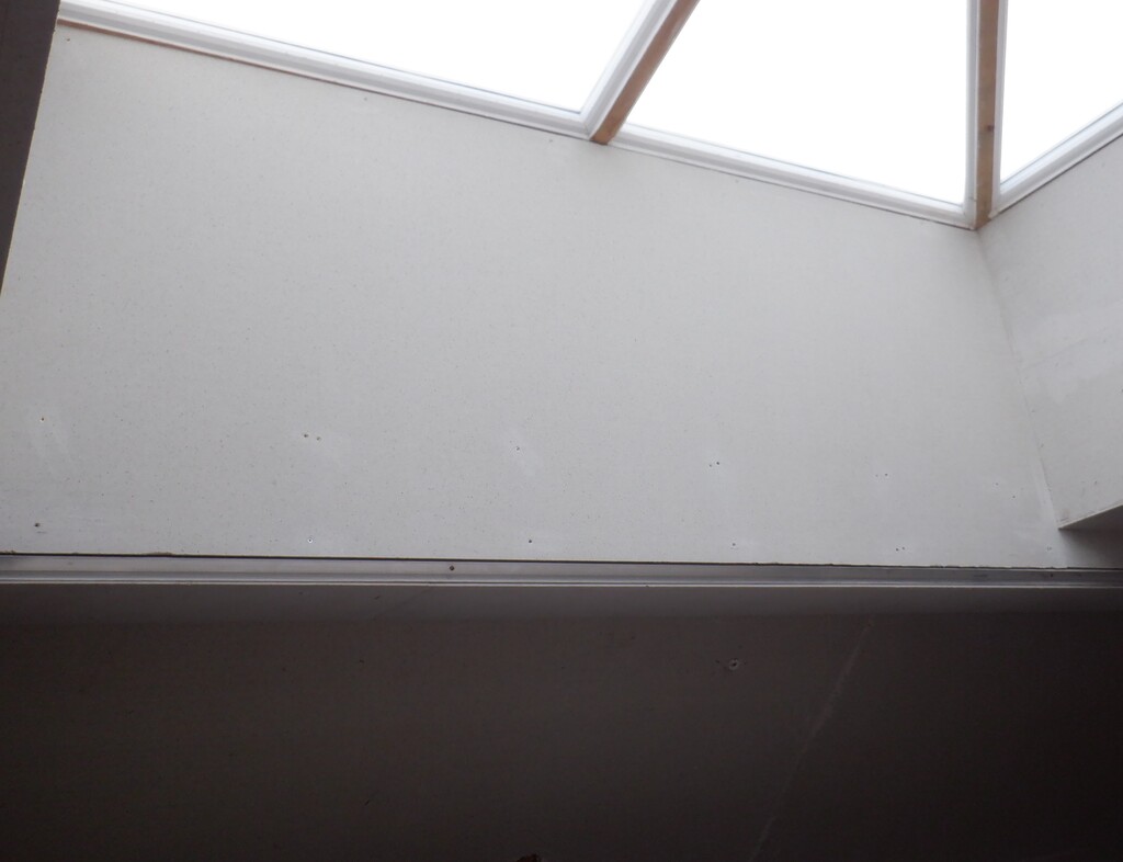
We put up the top rail precisely so that our lighting channel is one aluminium strip gap under the slope of each roof. We had to do four sections of the roof, the “A” section which has a 32degree angle slope, then coming around the corner, is the “P” roof which is a 40degree angle inclination, which reaches the “O” section that is even steeper at 45degrees and finally, a short “N” section which is back to a 40degrees angle. We wanted to be able to slide in our lighting modules which will be housed in an aluminium extruded U-channel shape. It is quite thick walls so it can spread the heat from all the individual LEDs but these long units needs to be able to slide in and out for servicing, hence why we needed to make sure that the top CLS horizontal rail are positioned so that the metal U channel will slide in and rest on this CLS timber, after we have put on the wall boards.
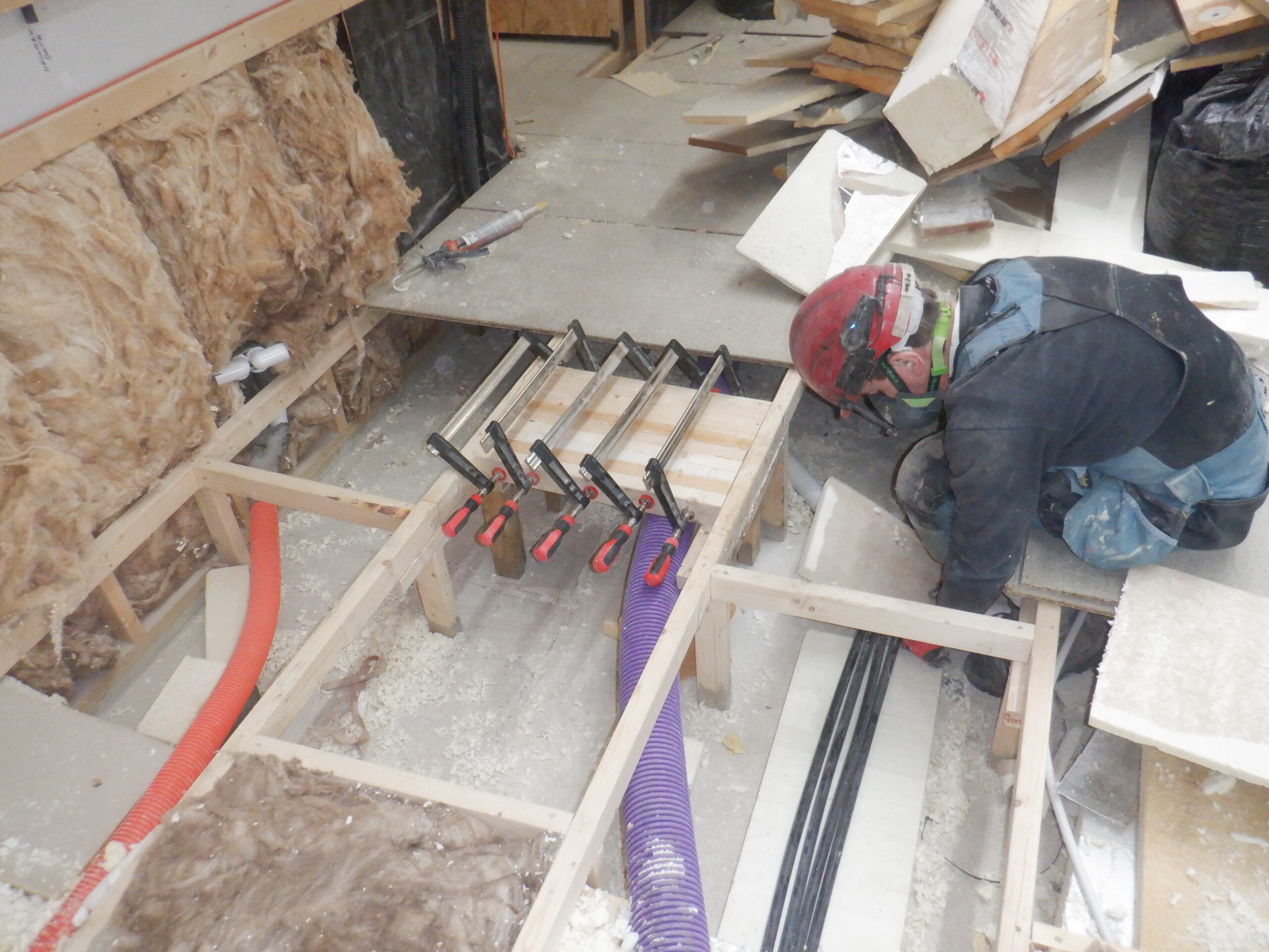
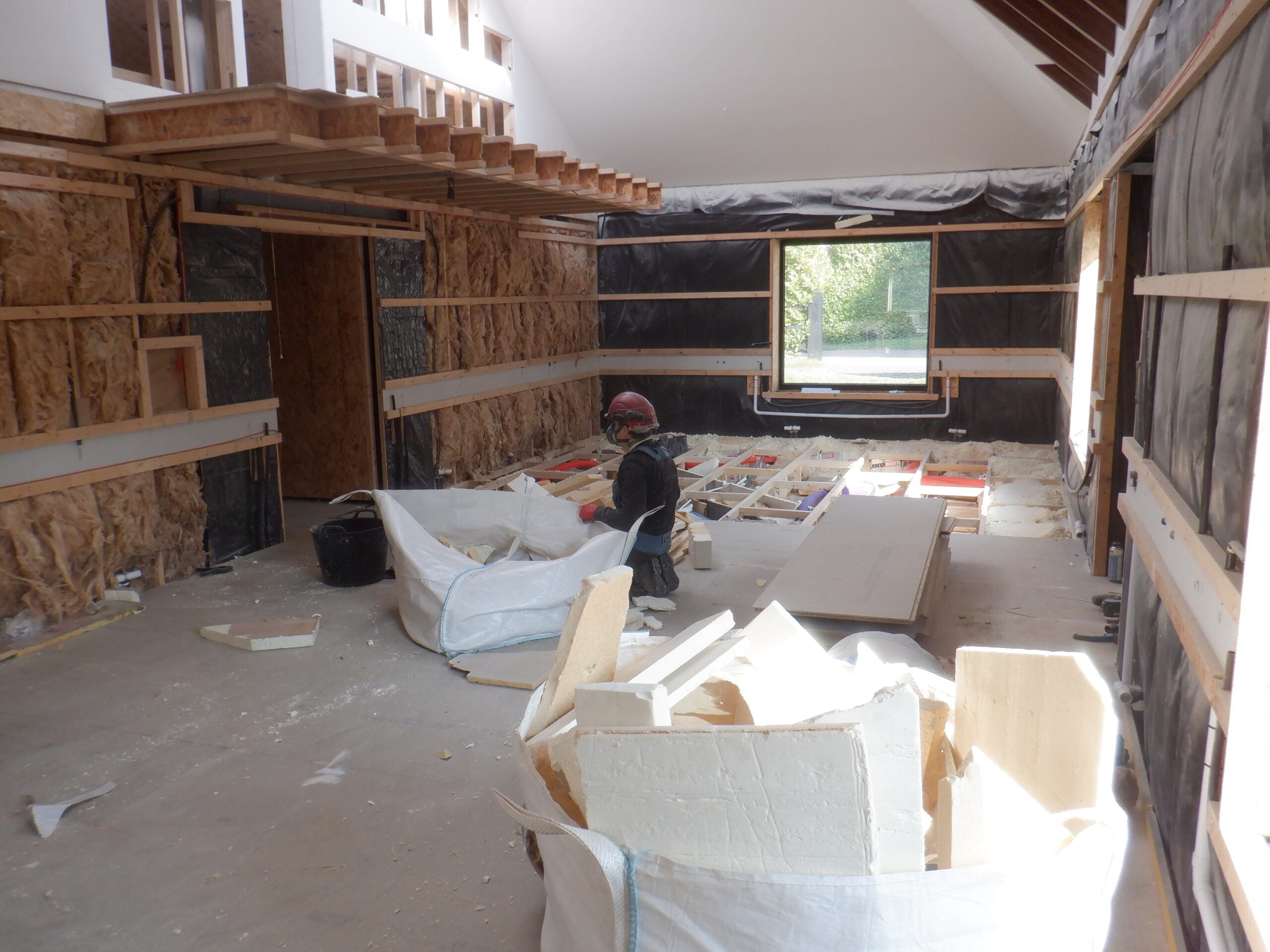
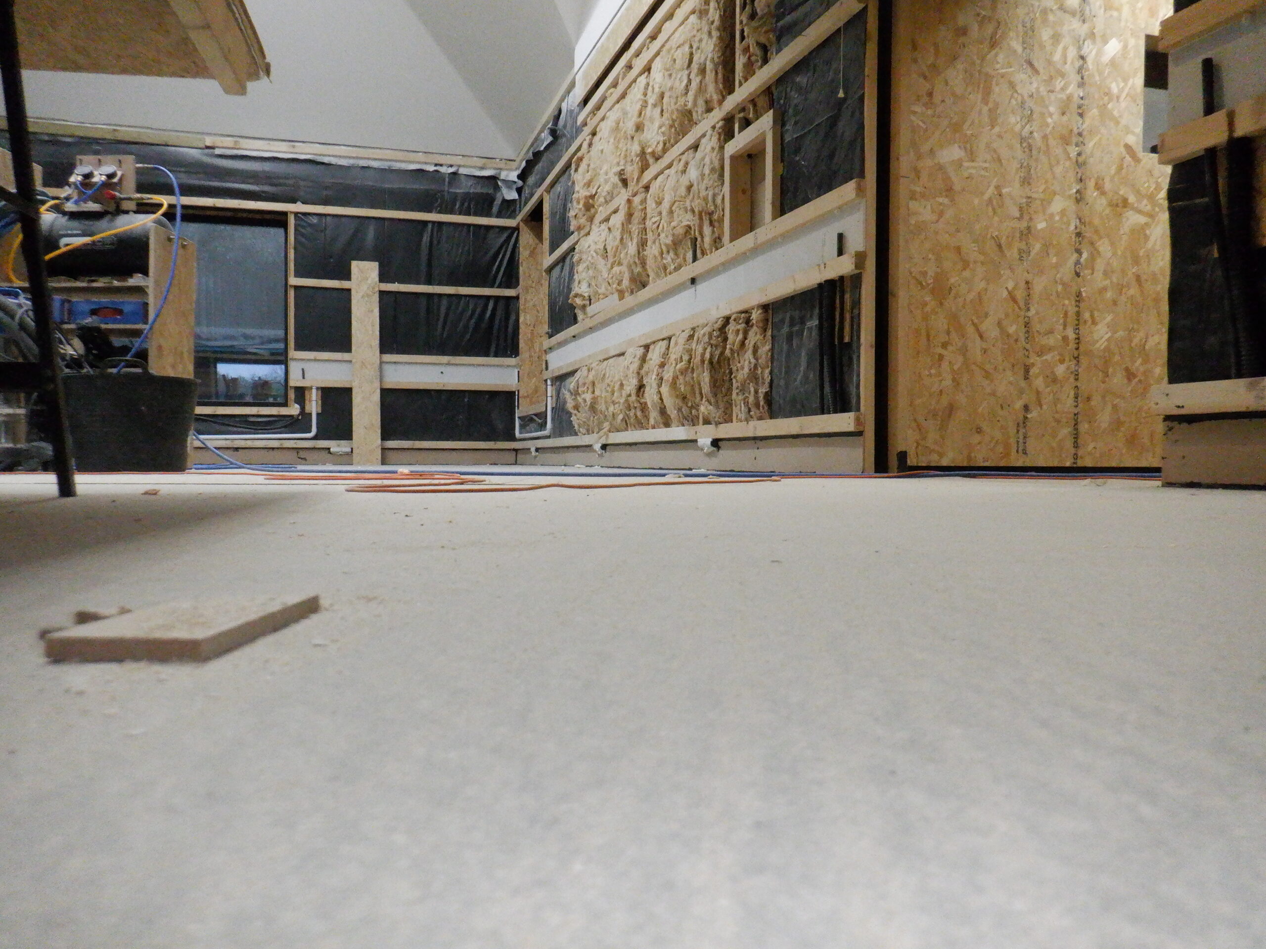
We then went around putting in a layer of glass wool horizontally, between the wooden rails so it fills the gap that would exist behind the OSB board and reduce the hollow sounds of wooden walls. This glass wool is supposed to be 100mm thick, but it is never is. We believe that the manufacturers are not careful enough when they squash the output of their factory productions into those rolls, ready to be transported. The gap that we are filling is only 38mm deep and so we staple up these so-called 100mm thick wool strips and they swell out only about 30mm or 40mm beyond the horizontal rails. This is sufficient for our purposes and the wall boards will squash this wool down and provide some degree of sound adsorbing filler, to make the overall resonance sound of the wall more solid.
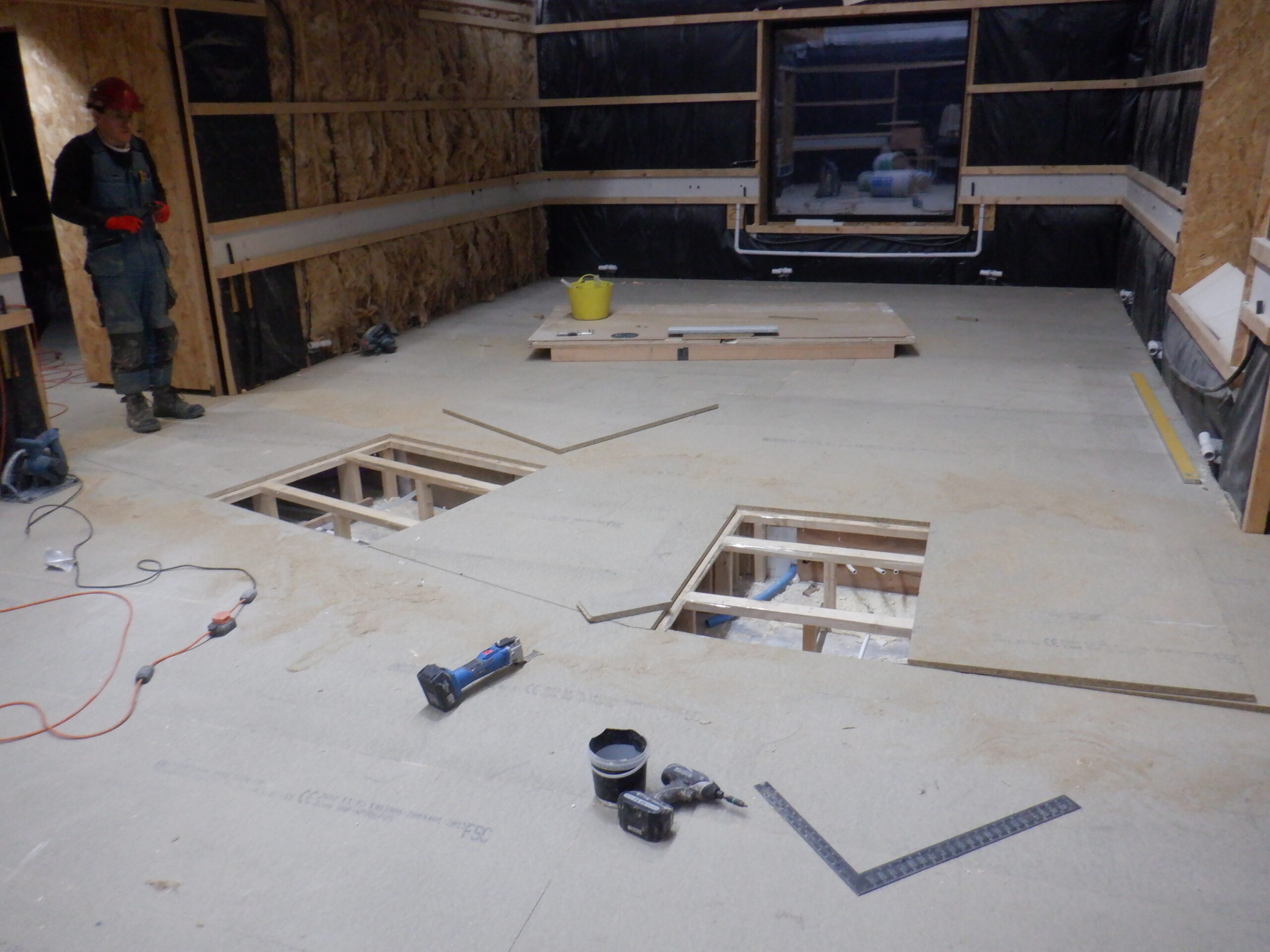
We then measured the two “control” boxes, one is the electrical junction box for all the cabling coming into the Great Room, as well as having a computer sitting there, looking after the various components that lives in this room, like lighting, sockets and speakers etc. The second cavity is over the doorway and that space will have the sliding door mechanisms and controls. Both of these boxes needs to have access panels and we will cut and remove the OSB sheet material later on after we have glued and screwed all the OSB boards up on the walls. Hence why we needed to measure the exact location and size of each box and its access hatch.
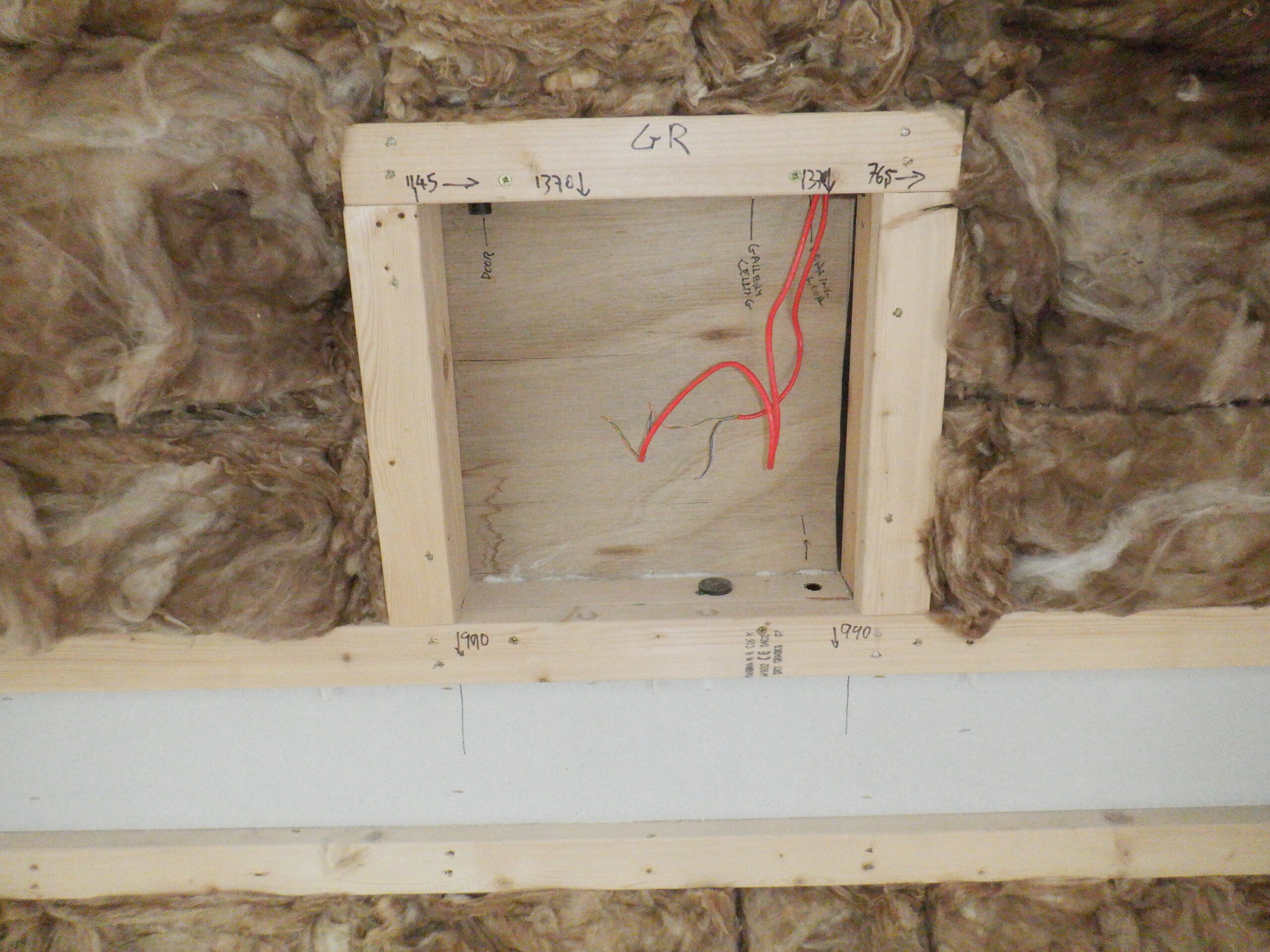
Great room Control panel location
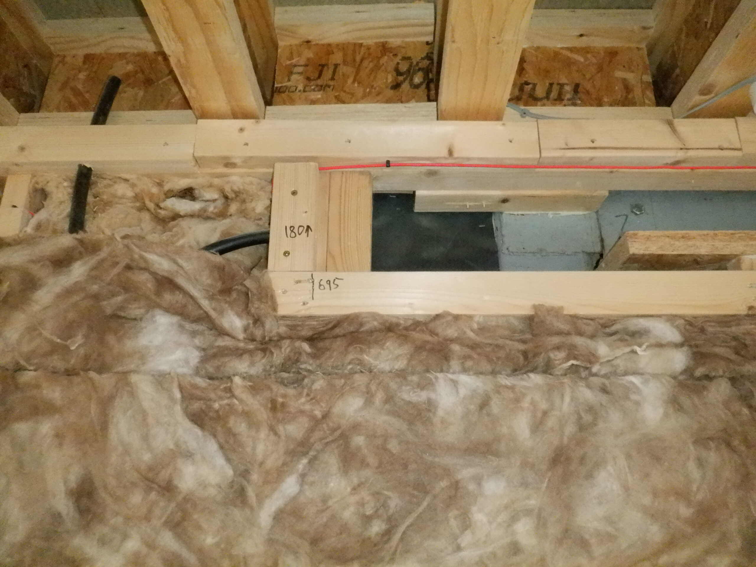
Great room Door panel location 1
Great room Door panel location 2
One of the task we had to do before we got into putting up wall boards, was to re calibrate our two router machines that has tongue and groove cutters in them. We wanted to move the cutters further out of the machines so that they could cut thicker materials we may need to do in the future. But we needed to make sure that we set them exactly the same position so that the tongues and grooves came out in the same place as before as the walls coming down from the Gallery and the gable wall coming around each side of the Gallery, has already a groove cut into the bottom edge of the boards, ready to receive the new sheet materials later on. So, we readjusted the two routers so the cutters are now sticking out by 25mm, each tongue (and groove) are 8mm across at the widest point so in 25mm, there will be three tongues (or grooves). We have two machines because we discovered that these sheet materials, especially the OSB boards, are very slightly varying in overall thickness so you cannot just simply flip the board over and run the cutter on the other edges because that produces a very slight misalignment and does not bring the two surfaces to a smooth finish. So, years ago, we invested in two machines, one to do the tongues and the other one to do the grooves, without having to flip the board over at all. It produces a very very good joint that is very smooth indeed, and incidentally, makes a very strong joint as well, especially using PU glue too!
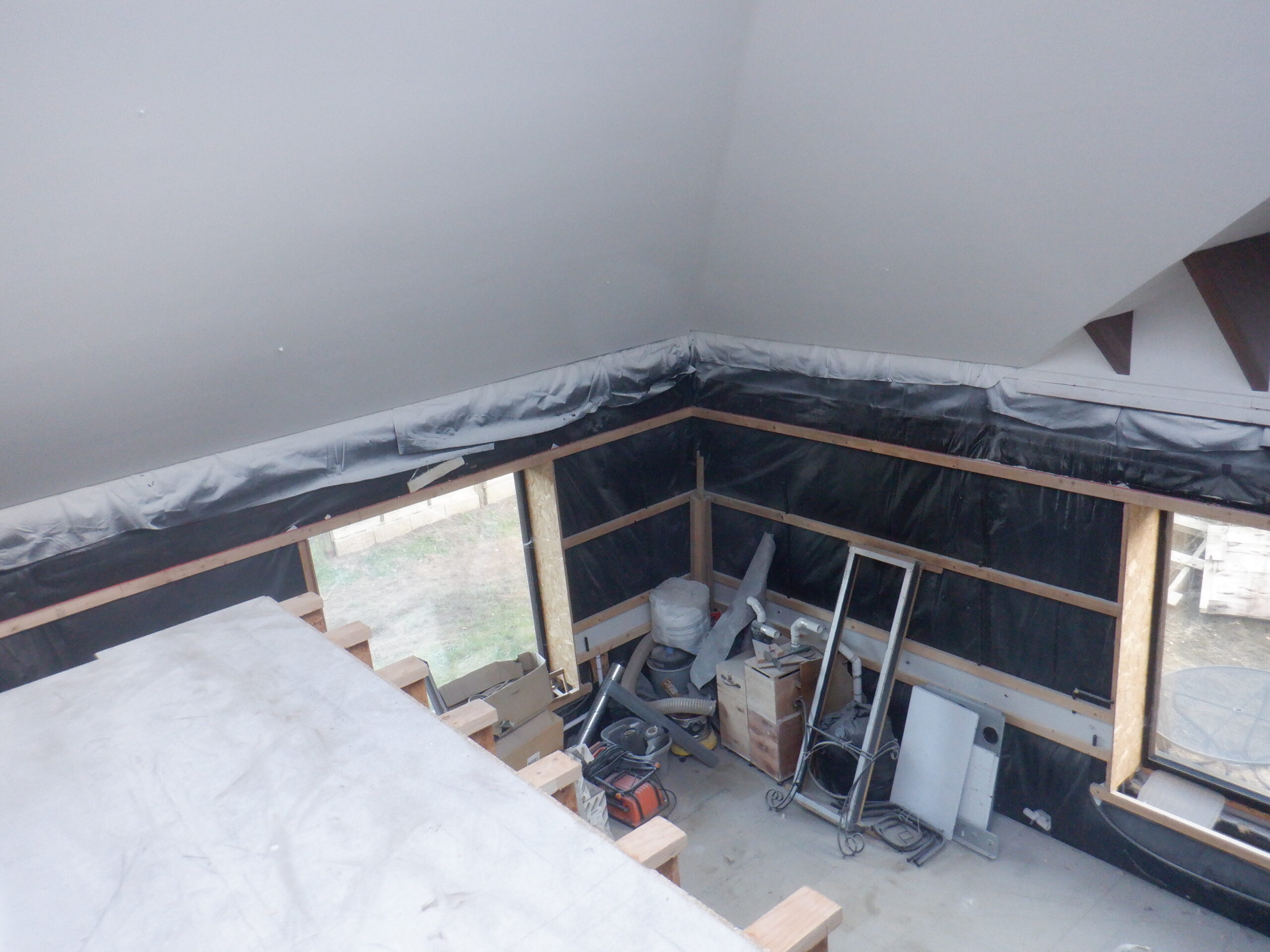
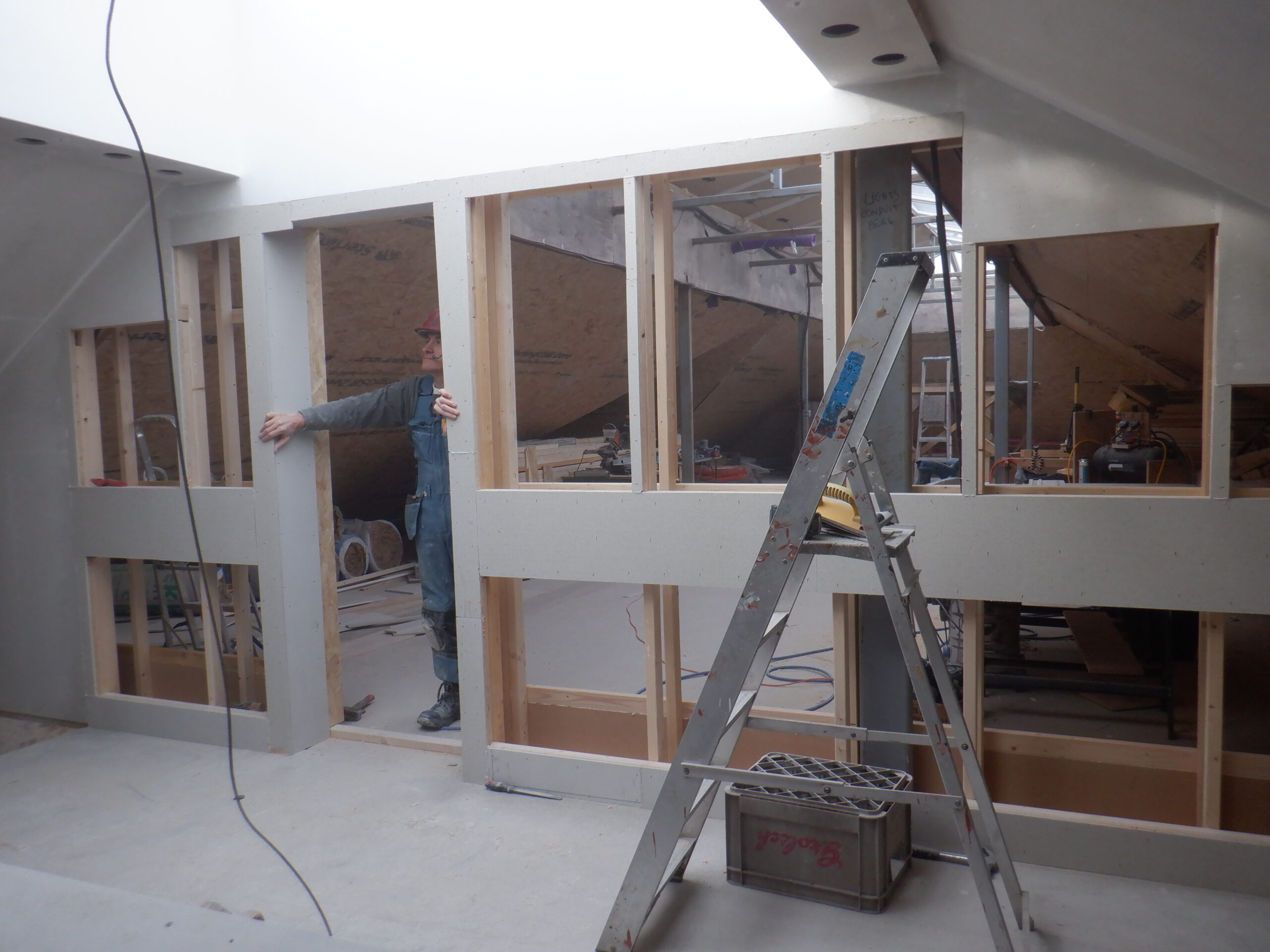
Here, at this point, we started putting up the first layer of wall boards, using 18mm thick OSB sheets. We started on the wall that divides the Great Room from the rest of the house and the two nearest rooms, namely the Kitchen and Bedroom One. It goes under the Gallery, but we needed to connect to the existing wall that is already fixed to the upper half of the Gallery. It was a bit fiddly but we made it, on both side of the Gallery and concluding in the far corner where we got our 4foot wide window. Next, we tackled the two short ends, also cutting the top edge of the OSB board with the appropriate angle, to match the slope of the ceiling as mentioned earlier about the aluminium lighting modules.
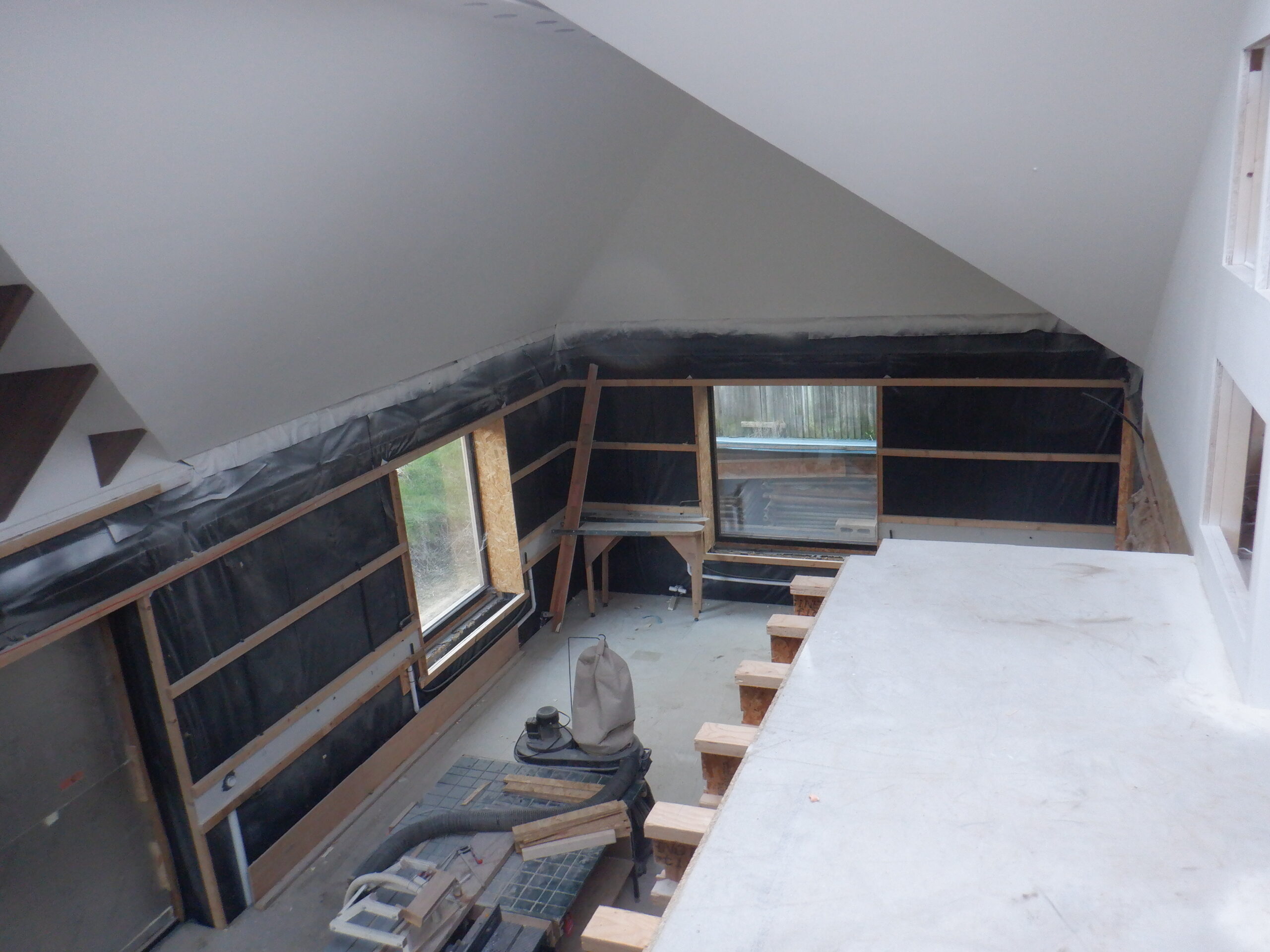
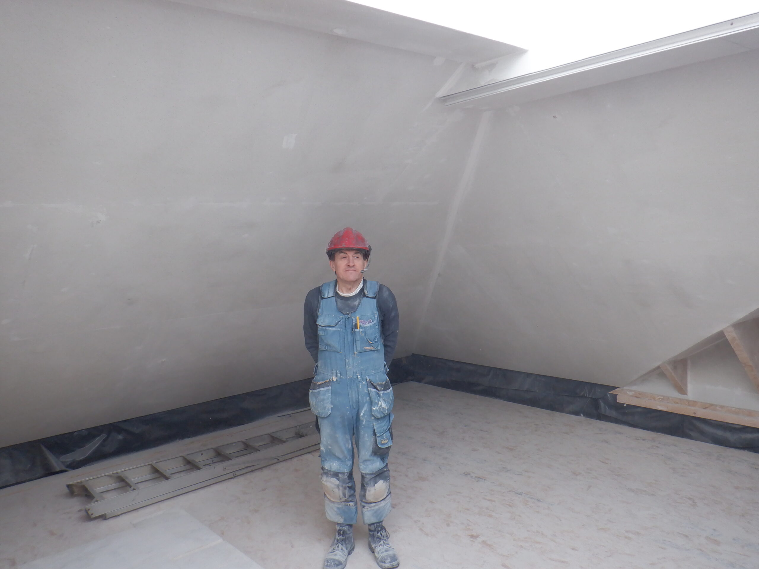
All our walls that goes up to the sloping ceiling are extra tall, measuring 2780mm or a bit over 9feet tall. That is just the wooden material itself, there is another 40mm gap at the bottom, and approximately 60mm gap at the top which makes the total height from floor to ceiling of 2880mm, or 9feet and 5inches!!
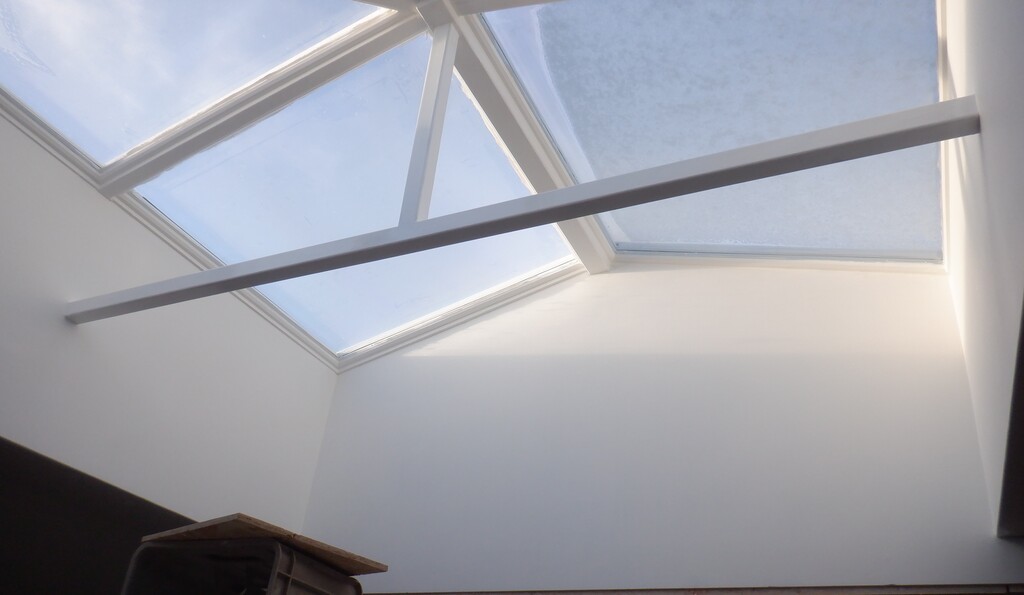
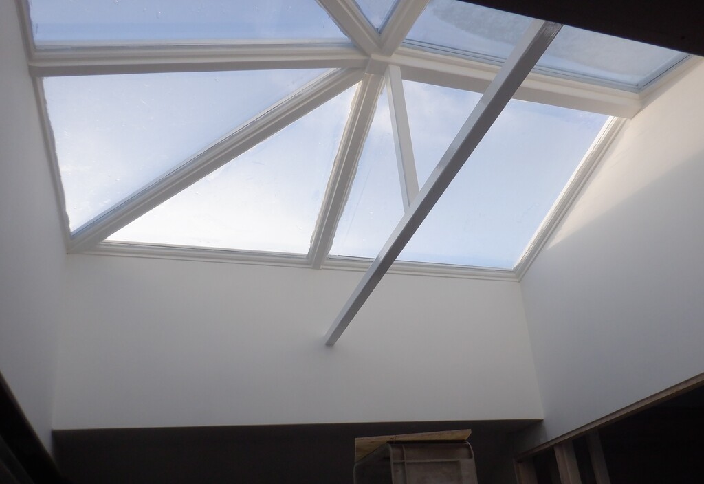
And to just finish this little point, the middle of the room stretches up, and up, and up to our mobile lighting unit, hanging at the apex of the vaulted ceiling, is very nearly 4800mm tall. We know this because we could almost get a standard length of CLS timber to stand upright in the middle! That is nearly 16feet!!
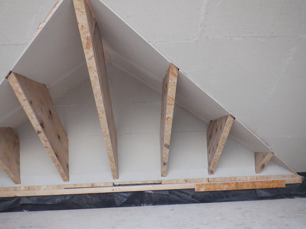
Anyway, we continued putting up the wall boards, having completed the two short ends, the “O” and “A” sections, and then we tackled the last long section that goes pass the Patio and Conservatory. We started at the doorway for the Conservatory and then worked back towards the “O” completed wall. It is much easier to put in the last piece of OSB board, cut down to exactly the correct size (and sometimes angle) and slide it into place by using the completed wall surface to slide along and force the joint nice and tight.
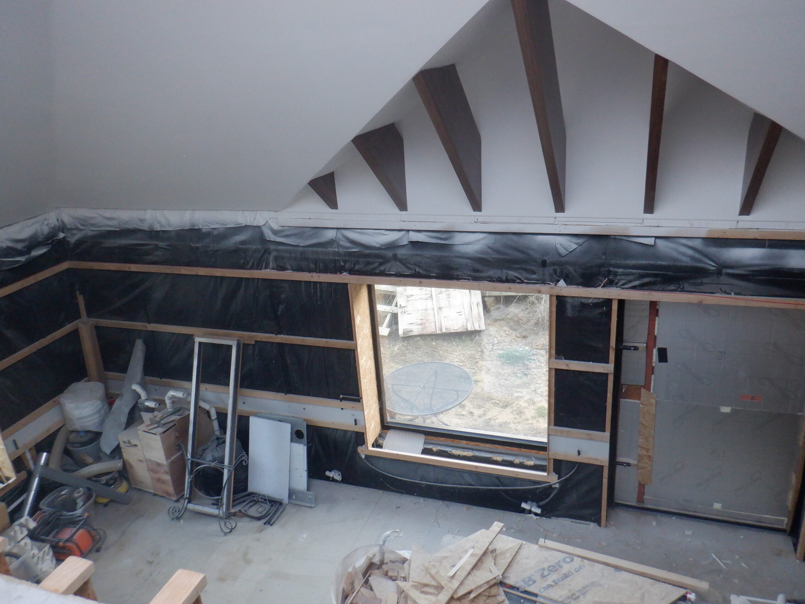
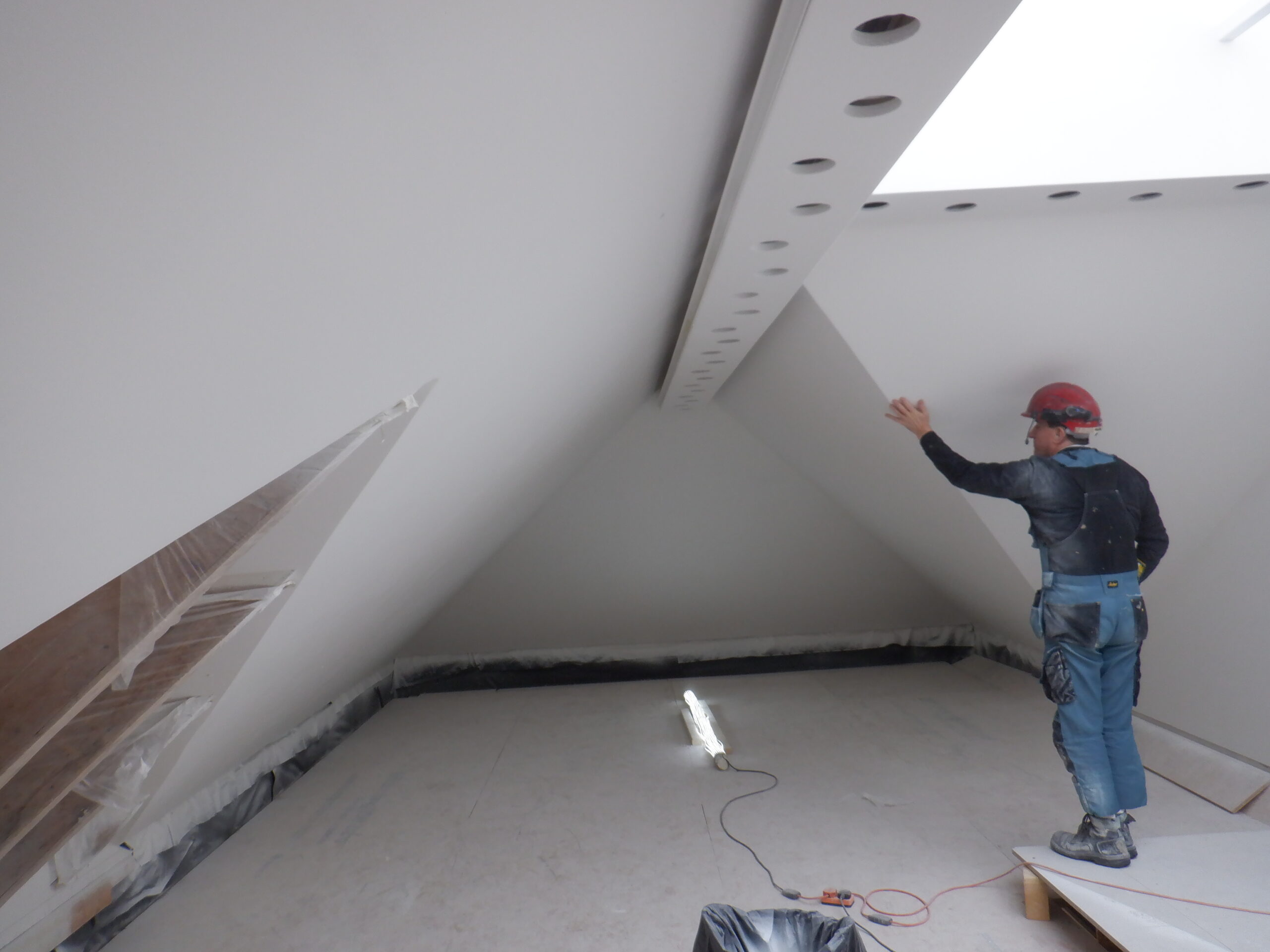
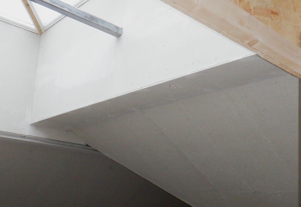
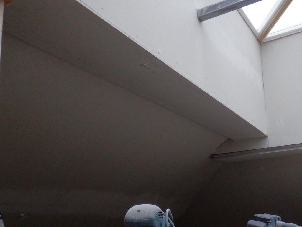
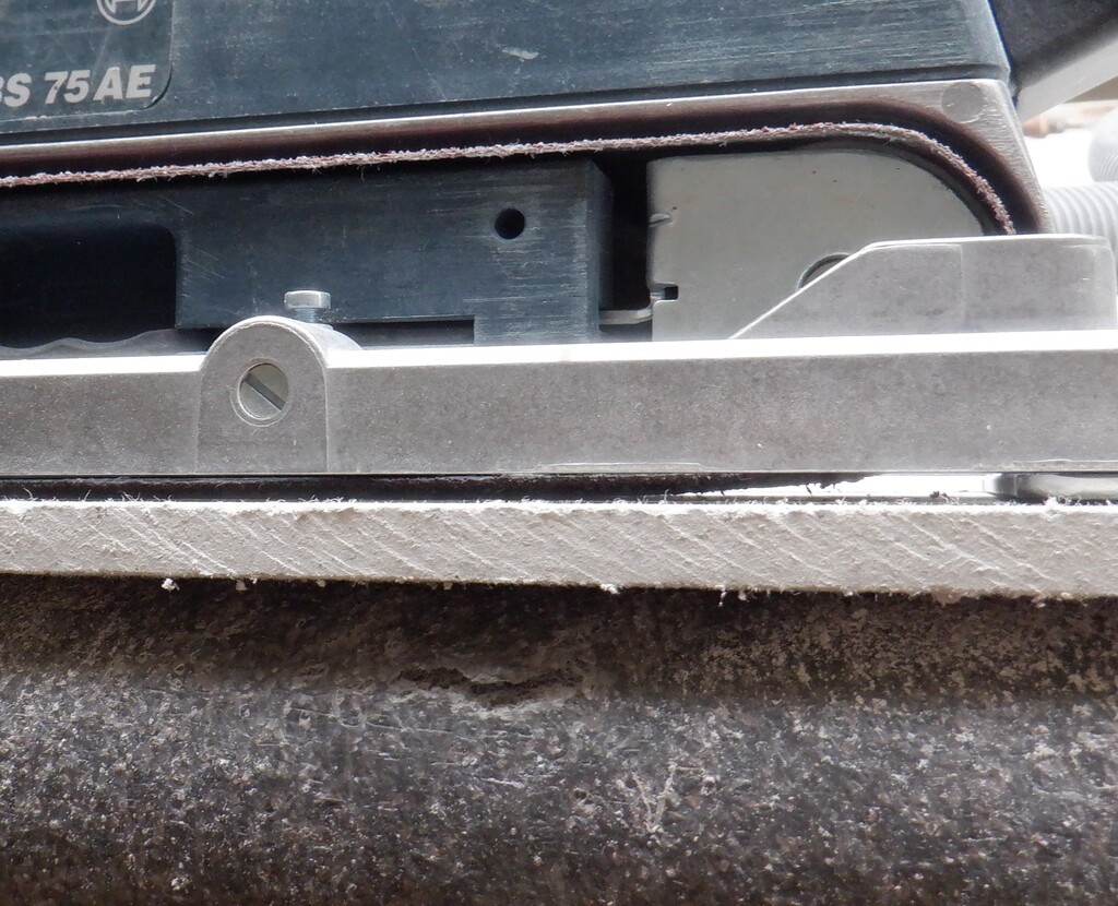
The other thing we needed to do special along this section, is the Dormer where we got our exposed rafters and gable triangle section of wall that defines the start of the Conservatory. We are wanting to mount our lighting modules, the same aluminium U channels, to slide in but this time, to sit vertically so the light output will shine upwards into the Dormer section. This meant that the top edge of the OSB board is shaped differently and also it is slightly lower as well. The aluminium channel will sit on this cut edge, providing a small gap underneath, approximately 15mm, to allow for our electrical cables to run pass and continue the circuits. We tested this arrangement by screwing up a small piece of OSB in various positions and holding up a piece of our fermacell plasterboard and tried to slide in the aluminium channel. We discovered that the vertical layers of fermacell plasterboard that we had fixed up a couple of weeks ago, and painted white, was very slightly causing the metal U channel to jam. So, we scraped the bottom edge of this vertical fermacell material, to increase the gap, and angle, to allow the metal channel to slide in. We used our trusty little surform “razor” tools to go along the entire length of this Dormer section. We have exposed the grey interior of the plasterboard again so we will have to paint that little bit again!
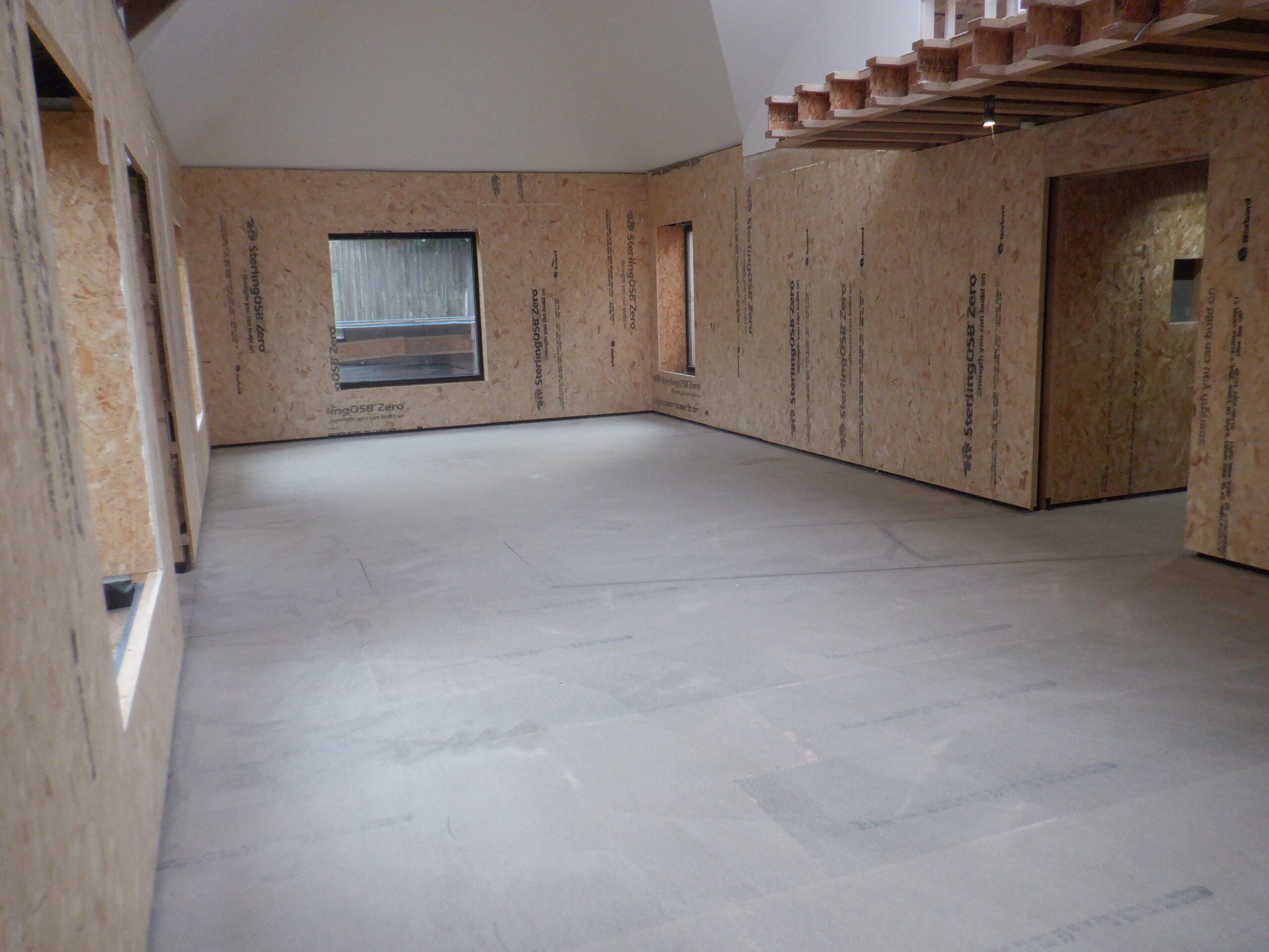
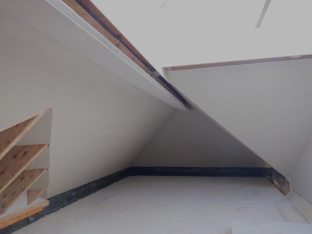
Great Room OSB Finished
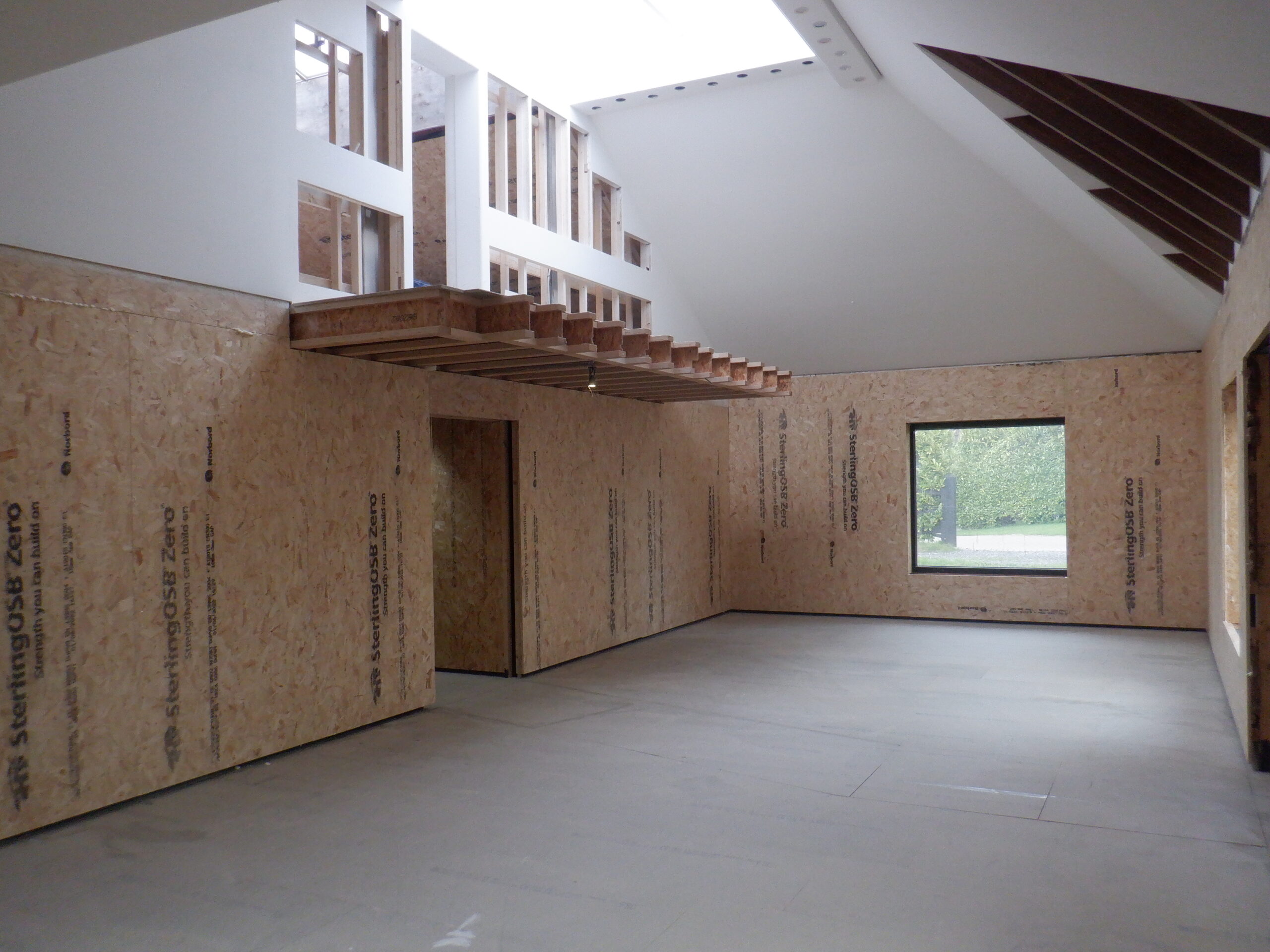
Great Room OSB Finished 2
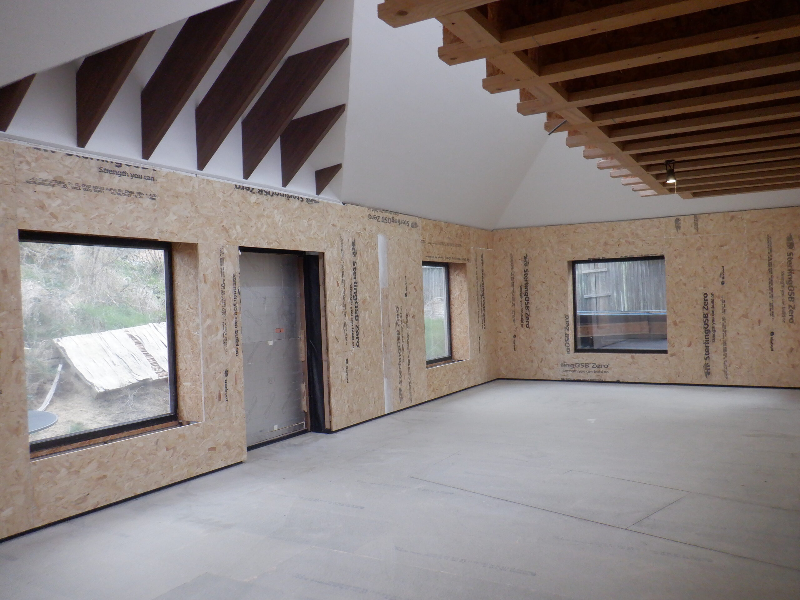
Great Room OSB Finished 3
This pretty much finishes the first stage of constructing the wall surface, the basic “rough” structural walls and they are now ready for the next stage, when we are ready, of putting up the fermacell plasterboard, shaping them nice and neat and painting them to the required colours, whatever that may be!!
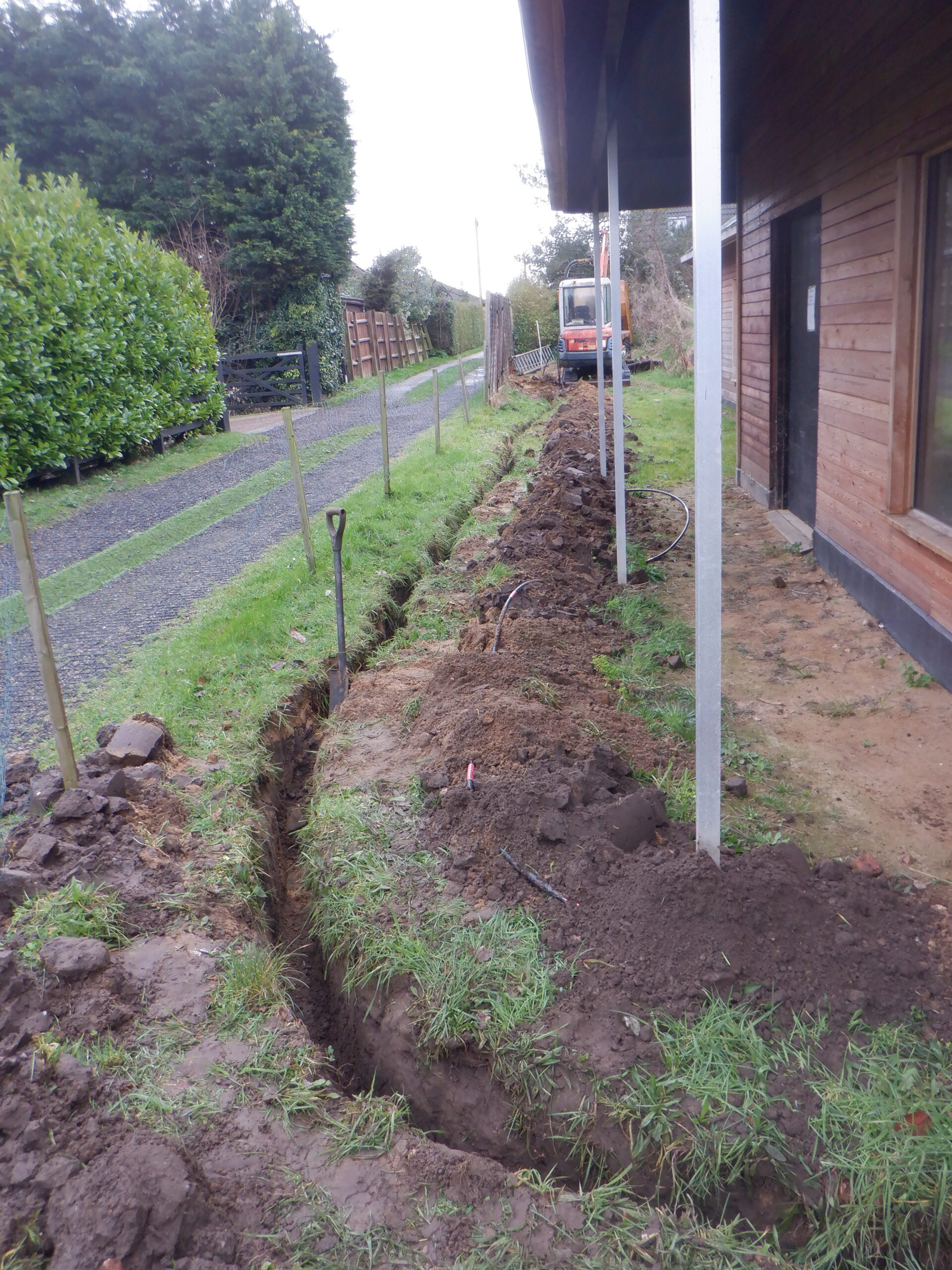
But, for now, we are going to have a change of scenery and go back upstairs to carry on getting the First Floor rooms mapped out and some of the wall’s framework built so we can build things like the water header tanks and ventilation ducting etc. We wanted a change! But, We promised ourselves that we will get back to the Great Room and finish it off during the Summer and present a completed “show room!”