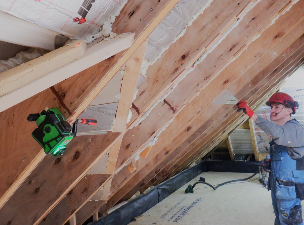
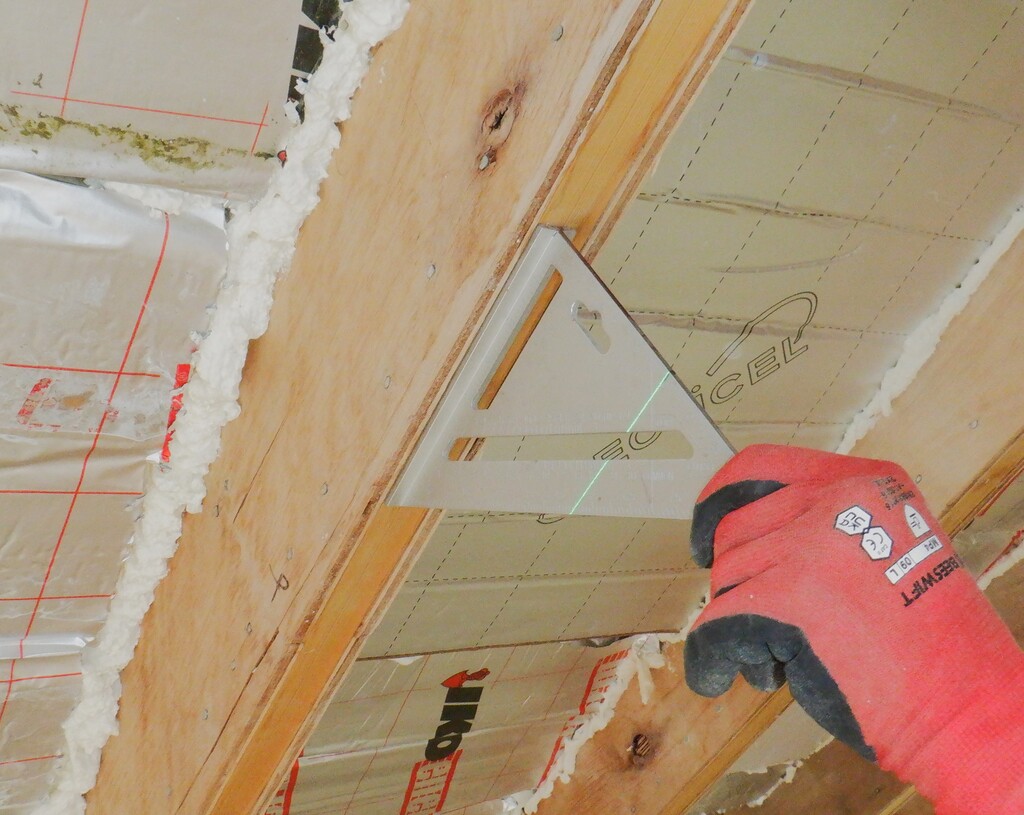
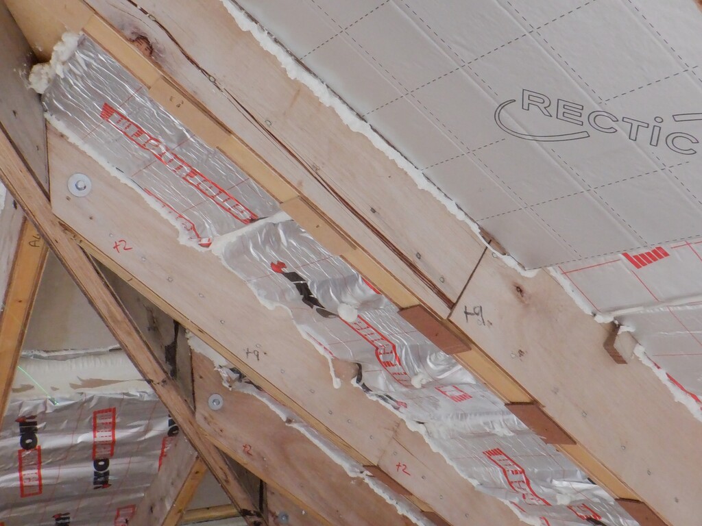
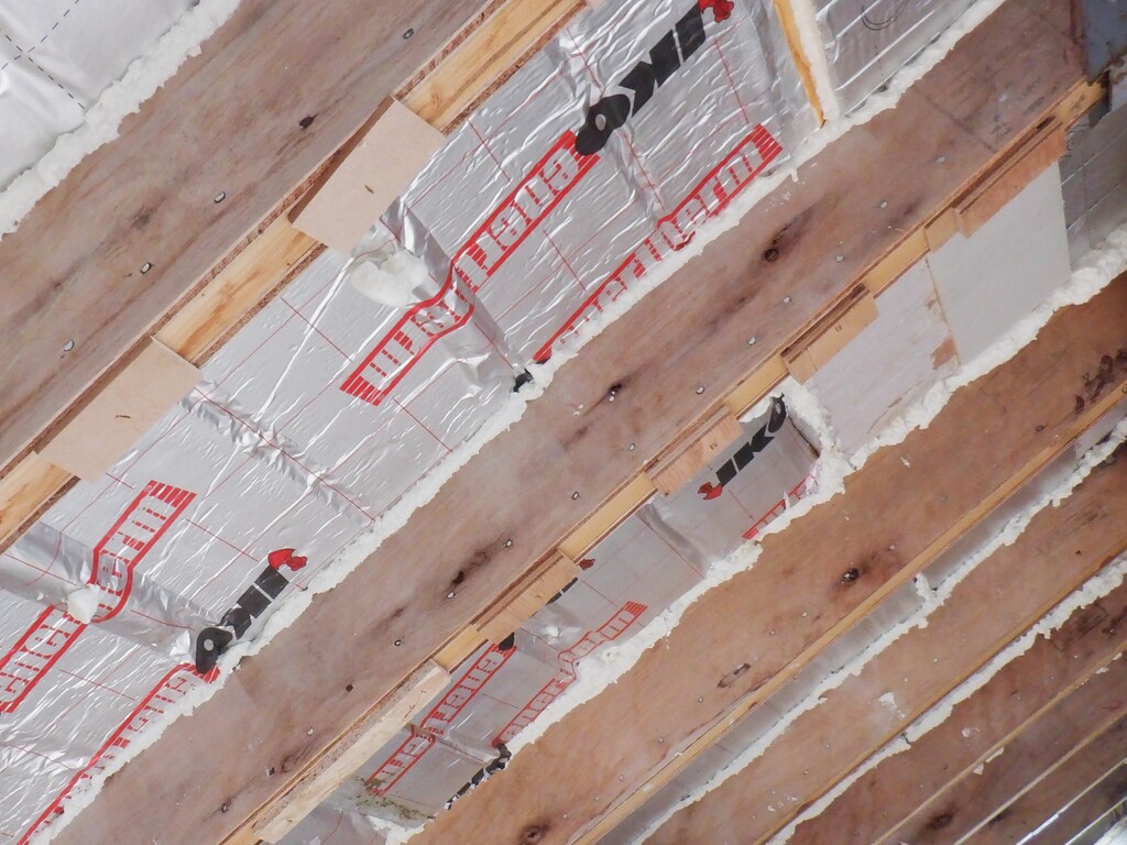
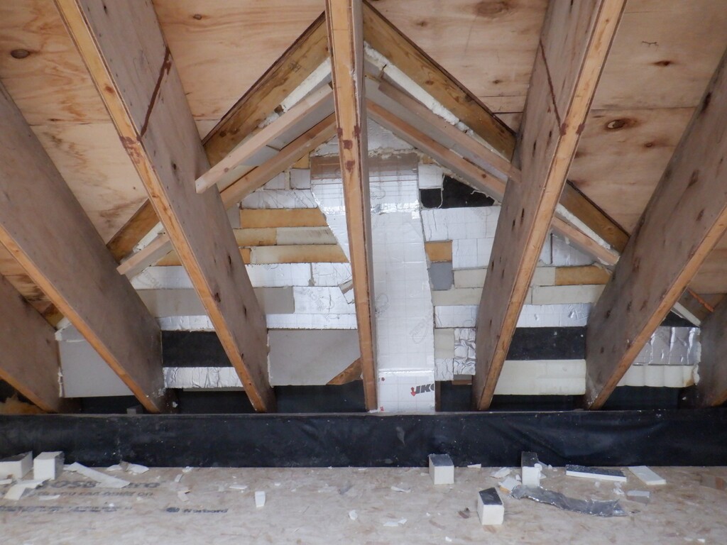
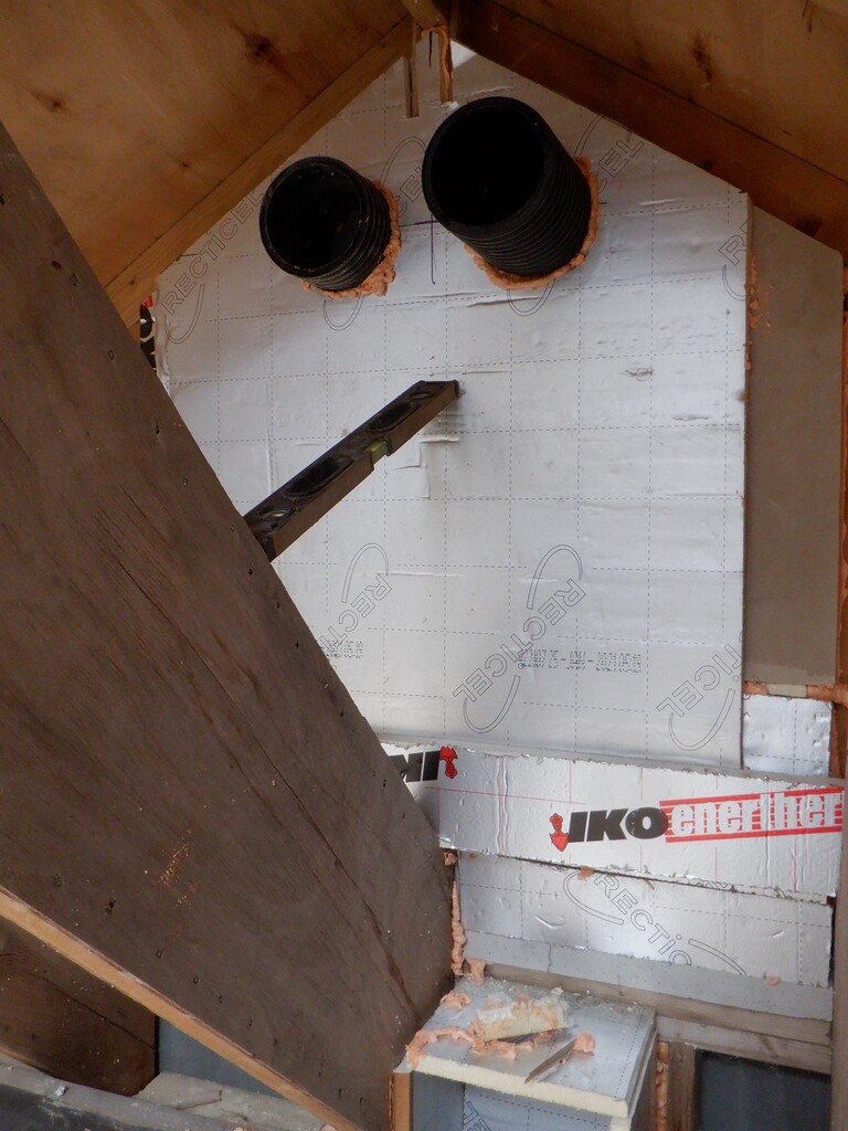
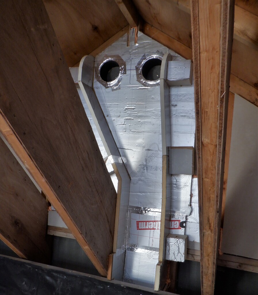
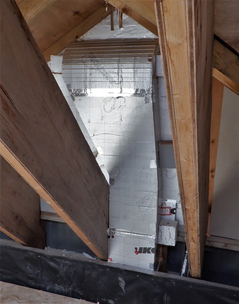
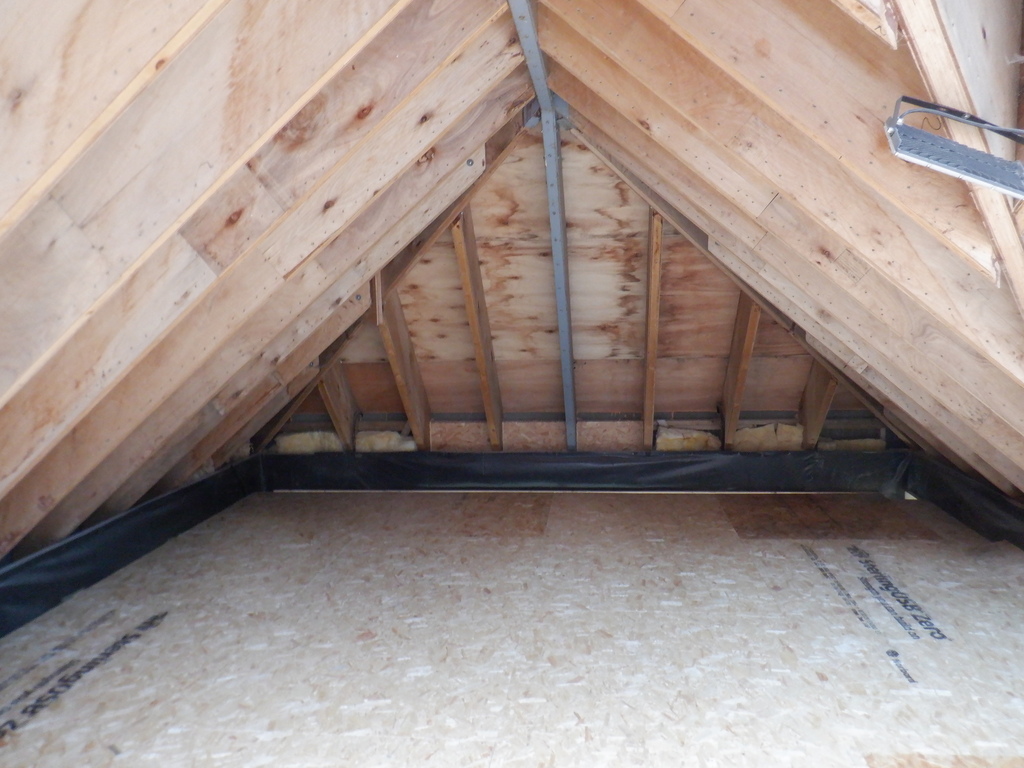
We spent the last three days in building a temporary working platform, right across the Great Room so we can access the rafters and get them filled up with insulation, cover them up but also gain access to the entire Skylight so we can measure and order the triple glazing units while we have this platform up. We will also put up the finishing surface, the Fermacell “plasterboard” sheets and paint it all brilliant white, including in and around the Skylight that is over the Great Room too. We want to design and build a lighting panel that will have the capability of being lowered for maintenance, adds or remove lights etc as well.
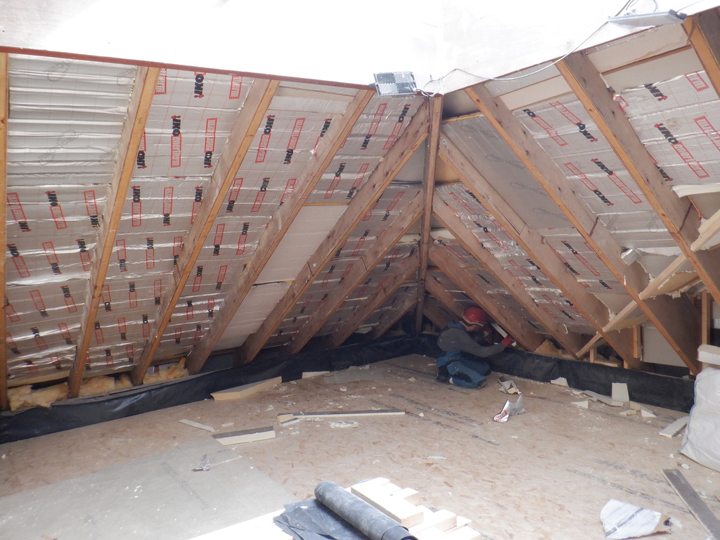
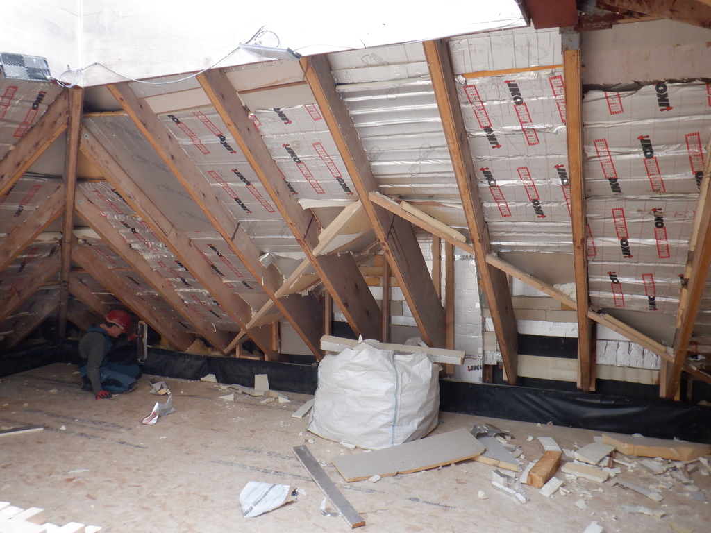
All this is difficult to do without this temporary platform so we proceeded by putting up our green laser line generator and then screw up a ring of CLS timber support rails around the edges of the room, so that we can then put a series of nine joists, separated by exactly 4feet, or 1220mm. We also put on an extra cross beam positioned at the end of the Gallery so that we can support these joist that lies beyond the Gallery. Then, we created a couple dozens of legs, along with a footpad to spread the load from the leg, and got them located every 4feet along each joist too. We wanted to make sure that our platform is good and strong and as sturdy as possible because we will be working with heavy pieces of equipment like a board lifter.
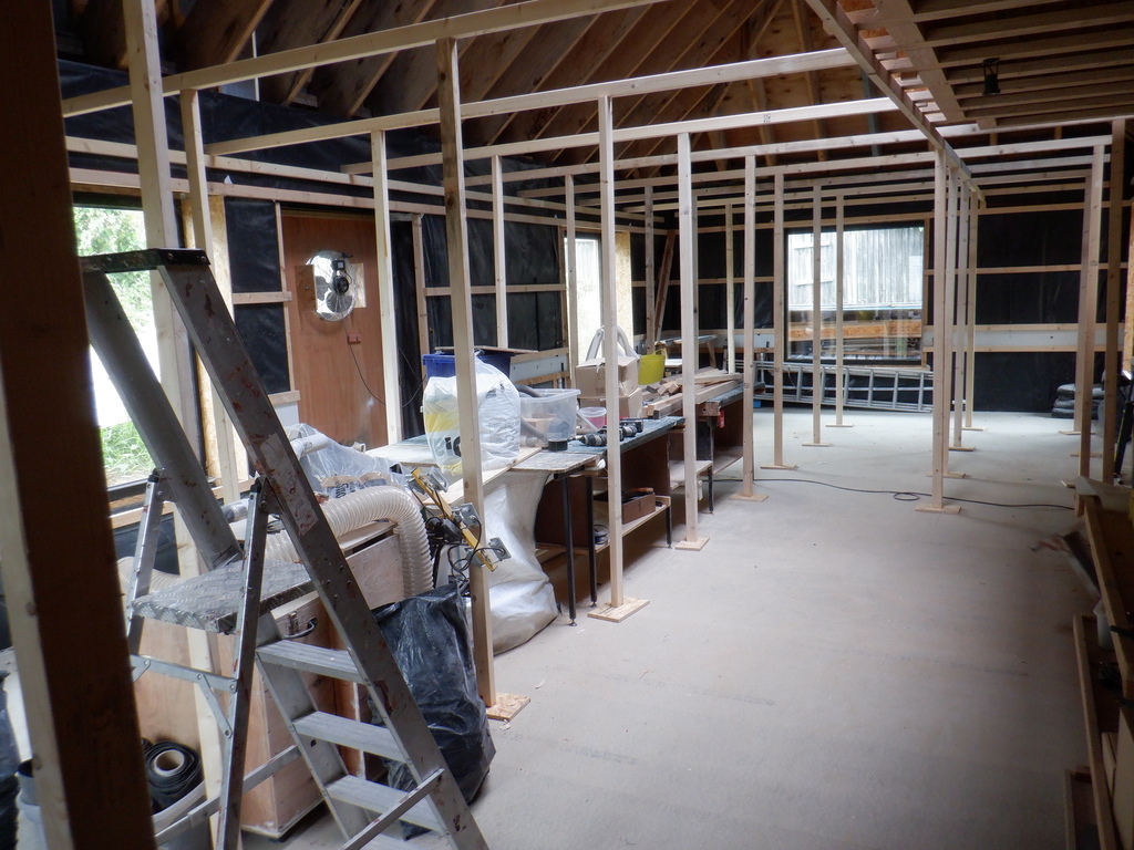
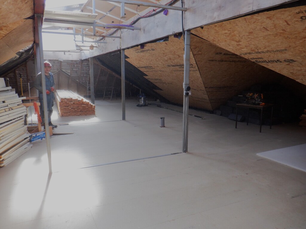
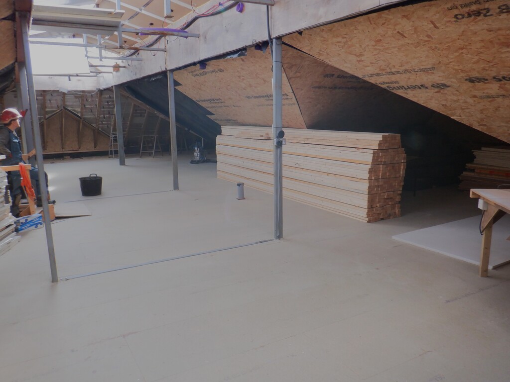
A forrest of legs 1
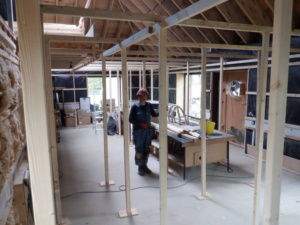
A forrest of legs 2
A forrest of legs 3
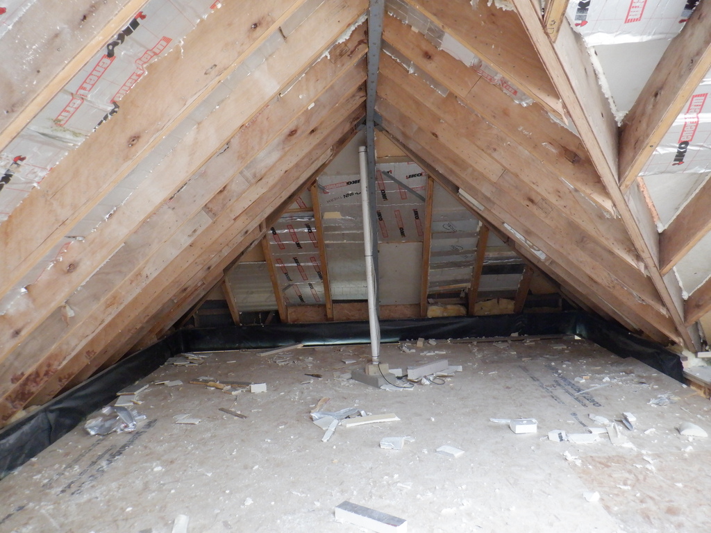
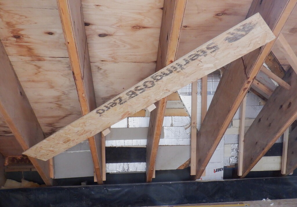
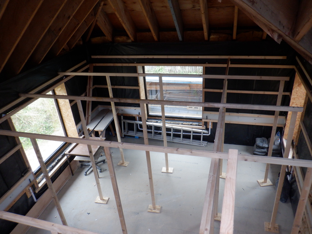
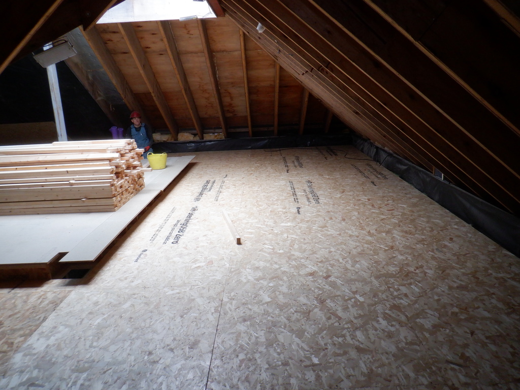
Next, we now brought up a whole load of 18mm thick OSB boards from our store room (Bedroom Two!) and shoved them one at a time, up onto the framework. We started next to the end of the Gallery and put in five whole sheets, in the eight foot direction, starting from the “A” wall and almost reaching the “O” wall, with only a few inches short. This shows that our Great Room is five sheets of eight feet each, a total of forty feet!
We carefully screwed plenty of screws to fix all the edges and for the second row, we sliced up an old sheet in half so we could offset the whole sheets to overlap half way. and finally, we put in a third row of another five sheets and again, there is only a small gap to the long “P” wall.
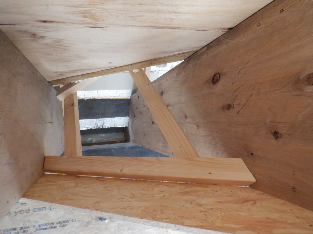
The gaps left and right of the Gallery were then filled in. the Kitchen side had a 1900mm board cut and fixed in, while the larger other side had two more whole sheets put in. This left a 240mm gap which we found lots of left-over pieces where we could slice them down and fit them into this gap.
Great Room ‘First Floor’ 1
Great Room ‘First Floor’ 2
Great Room ‘First Floor’ 3
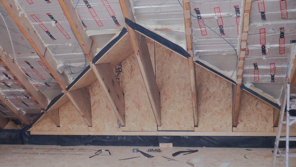
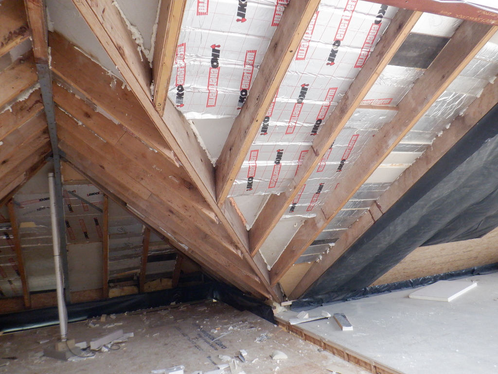
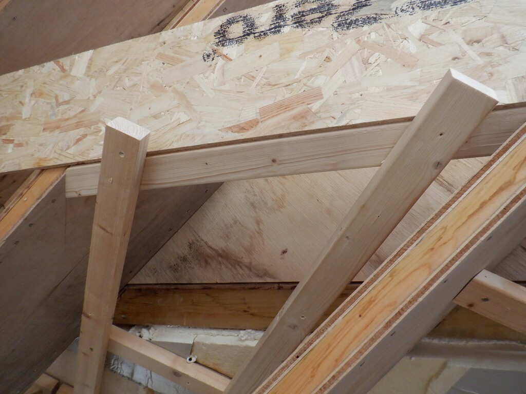
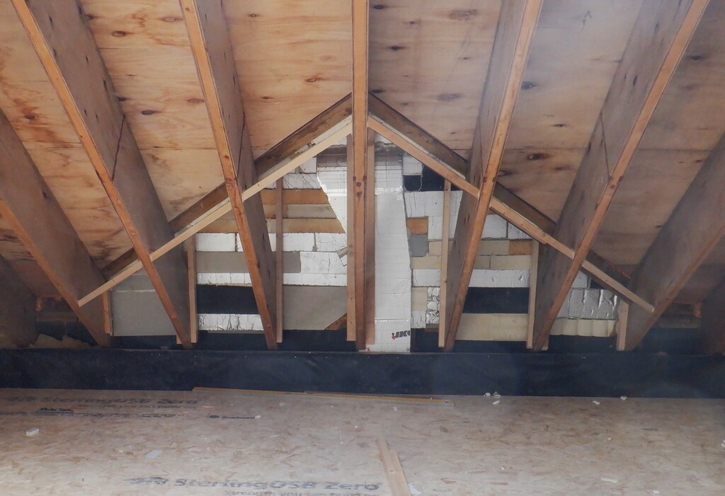
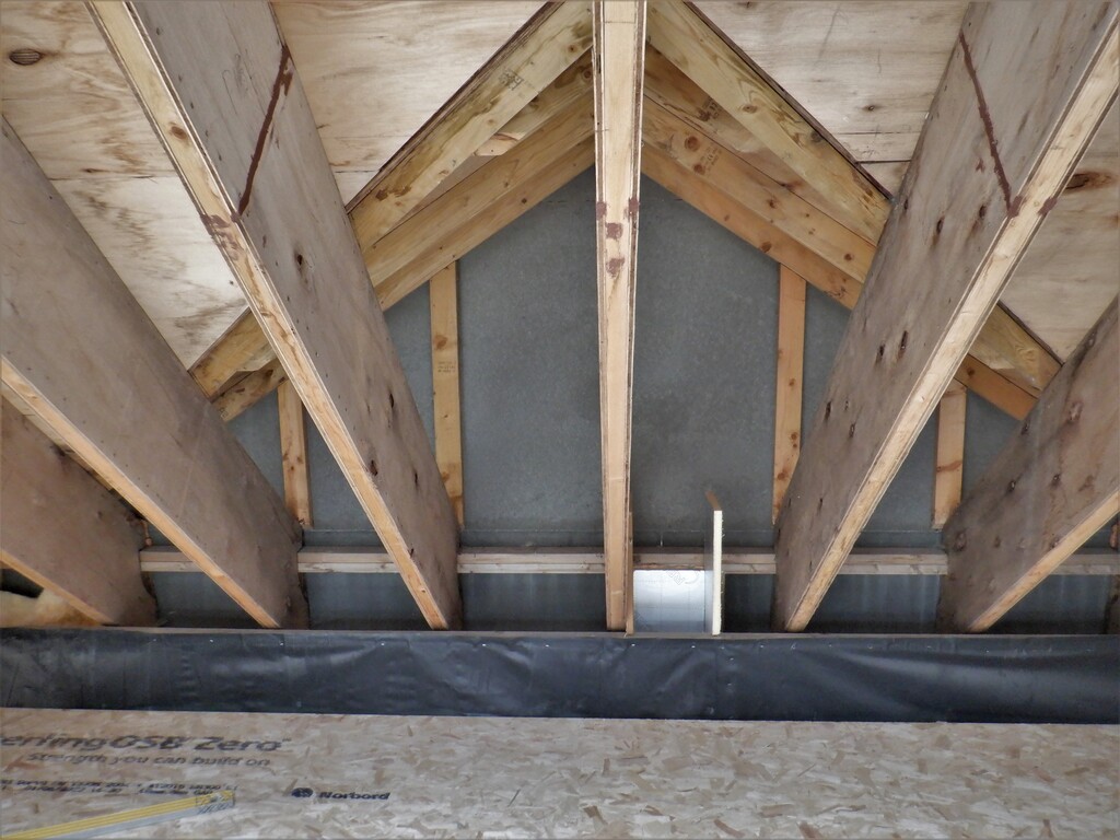
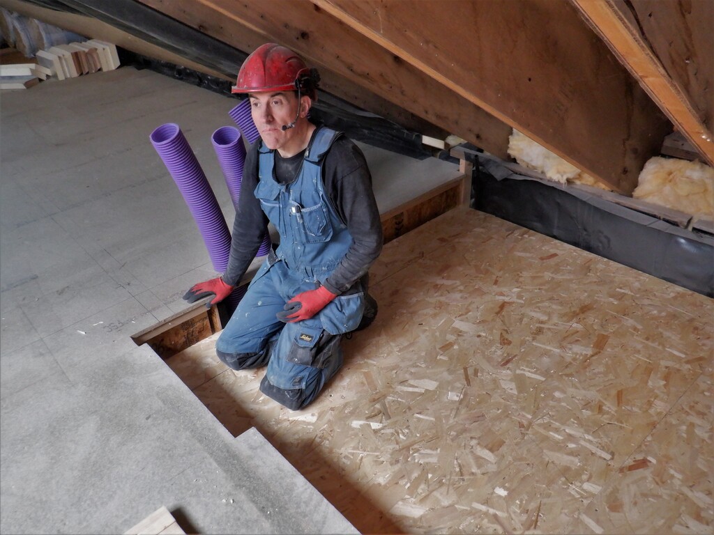
We now have an accessible working level, connected to the First Floor, with a small six inch step down (it makes it easier to get at the bottoms of the rafters) and we can get on in doing the last section of the roof to get populated with insulation etc. And, by the way, the width of the room is four whole boards plus a bit, so that is four times 4feet which is 16feet!! This is what is called a large space, in fact, it’s a Great Room !!
An because everything is screwed in place all the wood and OSB can be used for building the First floor walls later on so nothing will be wasted!