Blog

  • Shredding Machine Mark 2

    Yesterday and today, we built a second generation shredding machine. Our first one had a motor failure because we overdid it. The motor wasn’t rated for continuous use and it got too hot and burnt out some of its motor windings. Oops!!So, this time we decided to make use of our heavy duty stair-lift motor with a speed controller to drive a homemade axle loaded up with blunt old circular saw blades. We bought some 20mm threaded rod, got a piece of aluminium tube that just about slides over the rod and the saw blades then fitted on the aluminium tube very tightly. We made 18mm spacers from pieces of OSB board, stacked them together with 2 large nuts, to form a six bladed cylindrical object that spans about 200mm in both directions. We also bent over some of the teeth (by heating them up with a blow torch and bending it while it was very hot) so that it would chop into the foam rubbish pieces and break it up even more.

    We bought two pillow bearing blocks (yes that is what they are called!) that holds the axle nice and tight and we put a cog wheel on the back on the end of the axle which then has a chain wrapped around it and going off to the larger cog wheel on the motor, as you can see in the photo above.
    Also, you can see to how naked .. and dangerous it is currently looking!!

    So we then proceeded to build barriers and shielding to protect us from the spinning teeth and whirling chain ..

    And we also realised that we could connect up our vacuum dust extractor that we already use for when we are slicing up the foam boards and put the resultant rubbish into large bin bags. It would reduce the cloud of dust and pieces flying in all directions.

    We put the whole thing on sturdy legs and put a large lid on top to deliberately force us further away from the “chute” which is also a foot deep clear of the sharp claws too. We will always be careful with these sort of machines and made it much more difficult to be able to reach in accidentally or on purpose.


    So next week, we can start tidying up the large rubbish pile, plus also two large ton bags of stuff too.


    And when we got that done, we can move our slicing table out from that section of the First Floor so we can continue filling in our roof rafters along the J, K and L and the M section.

  • Progressing with Filling the Roof Rafters with Insulation

    We are making steady progress on filling our roof rafters up with the first load of PU foam insulation boards.

    We have now completed the I section, the H section, the G and F porch section as well as finishing off section E. Together with the previous sections D, C and B. We have used about half the quantity of the foam bits and pieces we bought and we still have a fair number of pieces upstairs, waiting to be used up.
    We estimate that we have completed just short of half way. So, it will be a race to whether we will have enough to complete the job when we get to the Great Room. This is not really a problem because we had originally designed for our roof rafters, which are 400mm deep, to have glass wool put in. This would give us an U factor of 0.1W per square metre per °C difference. For much of our roof, we will be even better than that, coming in at around 0.075 W in some spots.
    To give you some idea of what that means, our roof is about 300 square metres in total so if you multiply those two numbers together, you would get about 25W of heat loss through our roof for 1 degree difference. So if we run our house at 25°C, nice and cosy, and the chilly outside is hovering around 5°C, then there would be a difference of 20°C so multiply that number with the other number we got .. 25W times 20°C will give 500W of heat loss for the entire roof area of our house, on that chilly day! One small fan heater on low power would be enough to keep us warm!!

    We have reached a point where we need to tidy up the large rubbish pile that we have created (as well as 2 bags of bits accumulated over the last year)


    So we now need to build a shredding machine to reduce the rubbish to small lumps, ready to be poured under our floorboards in our Great Room.
    So read our next blog for a report on building another quick’n’easy piece of DIY equipment!!

  • Loading Up the Rafters With Insulation

    We finally restarted our building work on our house again, after several months of rescuing our Financial Crisis caused by the soaring runaway energy prices. We had the delivery of our second-hand PU foam boards way back last year and we have now started making use of it.

    We decided to tackle the section of the roof rafters upstairs over the front door region of the house. This is section B, C and D. Section C is actually a gable internal end to the roof as the rest of the hip roof is the overhanging porch on the front of our house.

    This meant that we had to build an additional internal wooden framework to form the backbone of the wall for that room, and then we proceeded to fill it up with 300mm thick of PU foam boards pieces. Then, the sloping rafters next to this gable end were also filled up with more PU foam bits and pieces.


    It was during this task that we were wondering to how much material we got outside and whether we were using it up too quickly to make it last long enough to accommodate the rest of the whole roof including making sure we had enough to do the Great Room which so far, haven’t had any insulation inserted yet. On conclusion, we decided to be careful and from now on, only put in one layer of PU foam boards in all the remaining rafters until we have done the Great Room and we can know to how much left-over we got. We then can go back and fill in another thinner layer in certain places to fill them up a bit more and use up the last of the foam boards pieces.

    Another aspect that we are having to be careful, is making use of any larger single piece of boards because we need to make sure we can make single “triangular” fillers for the rafters that contains either a valley or a hip. It would be quite tricky to try to insert small pieces, pushing them upwards against gravity and holding them there while the glue sets. Very awkward so hence why we are putting to one side any larger single pieces.

    This stage of our building work will be a long job, not at least because we are also doing our computer work alongside at the same time so we will only write a blog report every so often as we finish major sections of the rafters, like for example, We have done as far as possible for the moment, the B, C and D sections and we have even done some of the E section as well. We will just carry on and drop a quick update now and again.

  • Analysing, Designing and Implementing a Core Set of Procedures and Services

    This last month has been us concentrating on analysing what we are going to have in the way of a network, joining up all our microcontrollers and how they will talk to each other including providing a data stream of information to be recorded in our databases.
    This is an ongoing project and it will stretch into Phase 6, which is where we implements and commissioning of the various Utilities throughout the House and Garage. We are getting to a point where we do need to start designing the hardware level for the network subsystems, connecting each microcontroller distributed right around a room, or outside somewhere. There will be a master controller that will monitor this local network and then make a record of the activities plus passing on commands into the from the wider scope.

    We spent this month having a good tidy up of our various computer systems including rebuilding our old file system and creating a much more modular system running an Unix based platform. We got a build from the TrueNAS organisation which actually uses the FreeBSD implementation of Unix. We now have complete separated servers running on the machine, one for the Web side of things, another for the Database engine, a third for the File Storage itself. We will have other servers setup and running like a Plex Server to allow for media streaming too. The File Server makes backups of all our critical data and documents, copying a set completely off-site as well.

    Another area is making a connection to the national Met Office gateway and downloading their hourly prediction dataset for the next 48 hours from the time you request this service. It provides a forecast of temperature, wind speed, rain amount and their generic weather codes indicating those cloudy symbols or bright sunshine etc. This is very useful because we can then make an intelligent decision to whether we need to charge up the battery overnight .. or not as the case maybe. We can programme the Solis Inverter (this handles the Solar Panels and the nighttime charging) and tell it how much energy we wish to put into the batteries. We have written a series of PHP scripts to make the connection to their data gateway and translate their data into our database design. We can now run a query and acting on the information about our Solar Panels (like their elevation and compass direction), we can predict to how much Solar energy we could generate and act accordingly.

    We have also downloaded all the Solis data that has been recorded since we have installed the Solar Panels and also we have transformed this data and loaded this into our database as well. We can now see what our Solar Panels has been generating. We can compare against an average ten year sample of the weather condition at our Roselea location (using the European Space Agency’s satellite weather analyser that scans the entire Planet) – you can see the monthly breakdown below and get some idea of where we are. Amazingly, we are doing quite well against the predicted forecasted we had used and calculated for our 7 year pay-back plan.

    MonthActualPredicted
    September 2022289kWh324kWh
    October 2022460kWh355kWh
    November 2022204kWh251kWh
    December 2022167kWh209kWh
    January 2023207kWh229kWh
    February 202385kWh330kWh
    Totals1712kWh1698kWh
    Solar values from our system

    As you can see, we are actually slightly ahead of schedule .. so far .. it is all down to the weather !!

    As I said before, this is an on-going project and we decided that we will cycle between these two phases, 5 and 6, on a weekly basis. We do need to get on with the house and regain some grounds that we had lost because of all the work we have done on installing the Solar Panels, Batteries and Storage Heater etc.

  • Designing and Building of a Storage Heater

    Designing and Building of a Storage Heater

    This is a long awaited blog report to catch up on what we have been doing these last few months since before Christmas last year. We had to come up with a strategy to reduce our commitment on the stupidly high electricity prices. We have already invested in a large array of Solar panels and a Battery system but we found that it was not big enough to cope with our temporary living quarters in keeping us cosy and warm. We found that we needed even more energy during the daytime than what the battery could deliver, even if we charged them up using the cheaper night time rates, which we are already doing.What we needed was another Battery pack but what with the war in Ukraine and the chaos of all the world shortage in materials etc. .. The exchange rates were very poor and it would have costed us another £2000 at least and even a third pack would only bring in additional 15kWh of energy storage. We really needed another 30kWh to 40kWh to cope with the coldest days in our living quarters.

    This means a more traditional storage heater design, taking electricity and storing it as heat in ceramics. But it is really difficult to find a shape of size that will fit into our existing arrangements and also it seems that the cheapest ones that is big enough for our needs would be also cost us well over £1000 as well.

    So we fall back to our usual solution .. Build It Ourselves!!

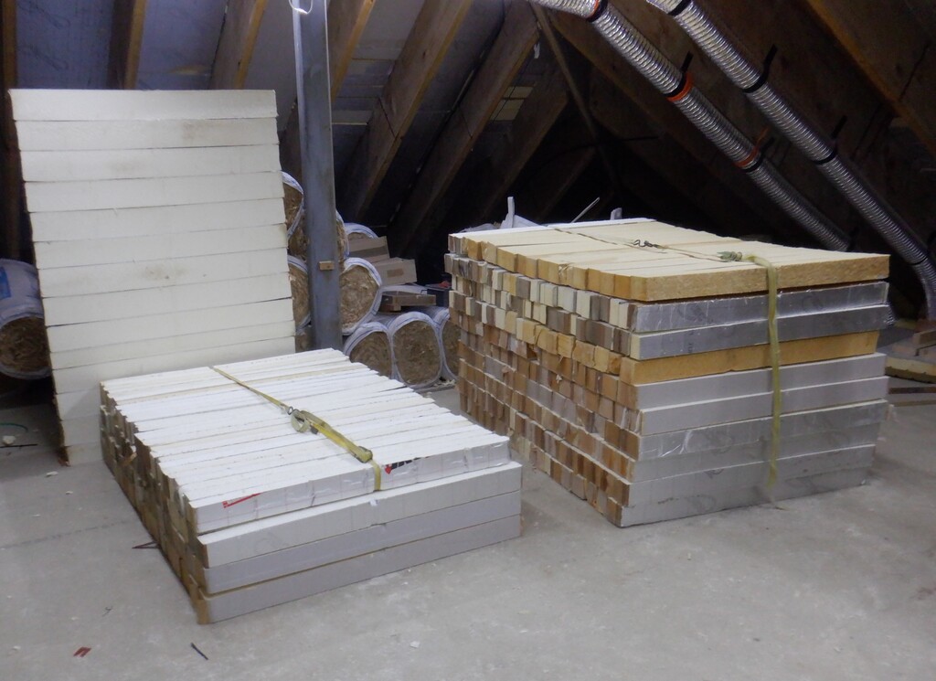
    We had some steel ‘rebar’ that were the left-over from doing our swimming lane so we designed a frame for the heater, an inner cage that will hold trays of house bricks and an outer frame to hold the covering, with space between for insulation. We had a load of clay bricks sitting outside, not doing anything so we grabbed 180 of them and got them all washed in hot soapy water.

    Designing and Building of a Storage Heater

    Cleaned-bricks-waiting-to-be-used


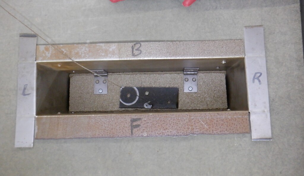
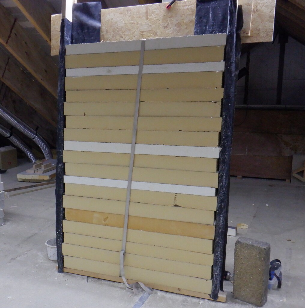
    We then cut up thin steel sheets we had and bent up a narrow edge to form the metal trays then welded the corners, each tray holds 2 layers of 7.5 bricks. Next, we bought some high temperature mortar mix, designed to be used in brick kiln ovens and cemented the first layer of bricks together and then buried the electric heating wire in a layer of cement before sticking down the second layer of bricks on top.

    Designing and Building of a Storage Heater

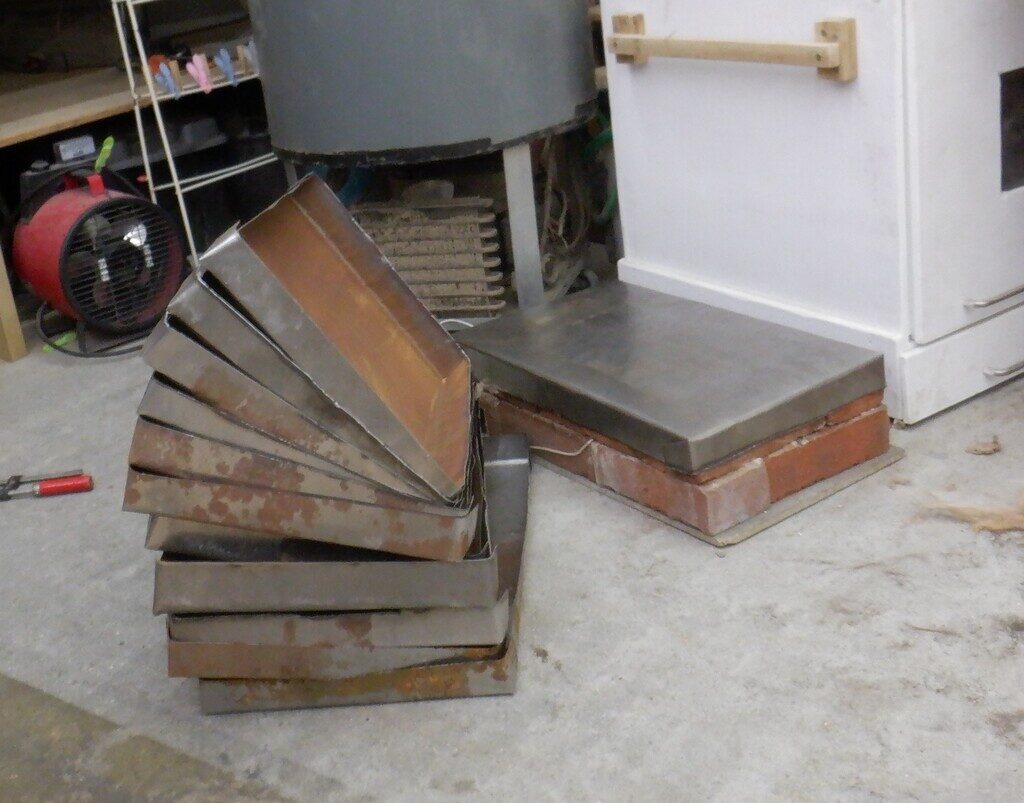
    Storage-Heater-Brick-trays

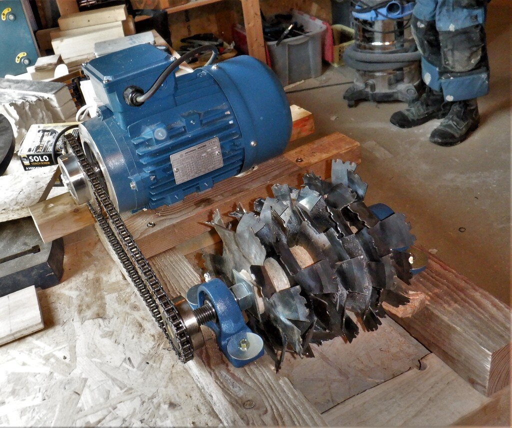
    The electric heating wire is the standard industrial type, an alloy called nichrome, which is composed of 80% nickel and 20% chromium. We wanted to end up with a pair of trays drawing 1kWatt of energy from the mains national grid. We made ten of these trays, to fit into the steel cage, to form a tall stack.

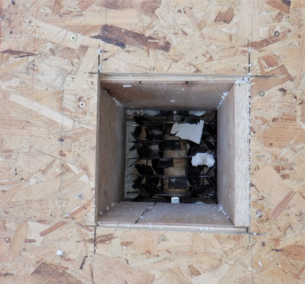
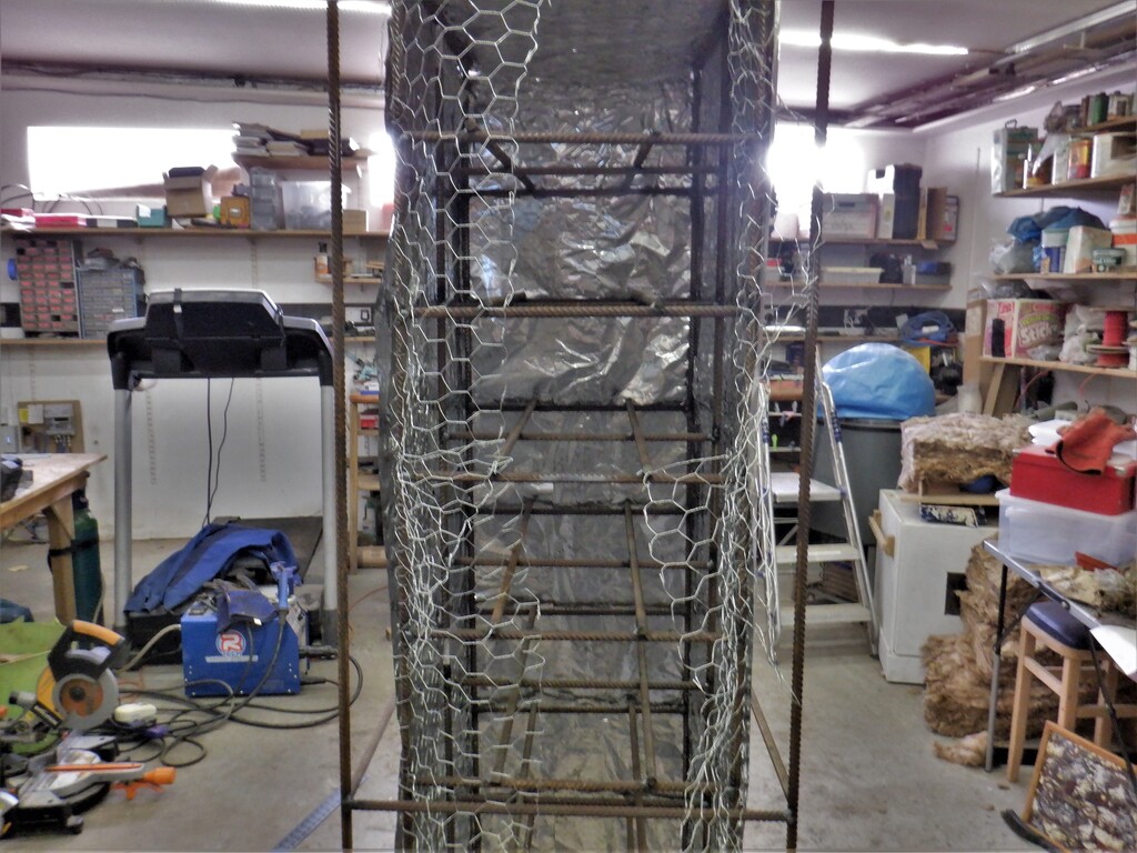
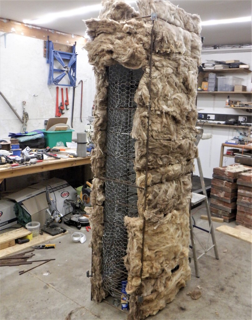
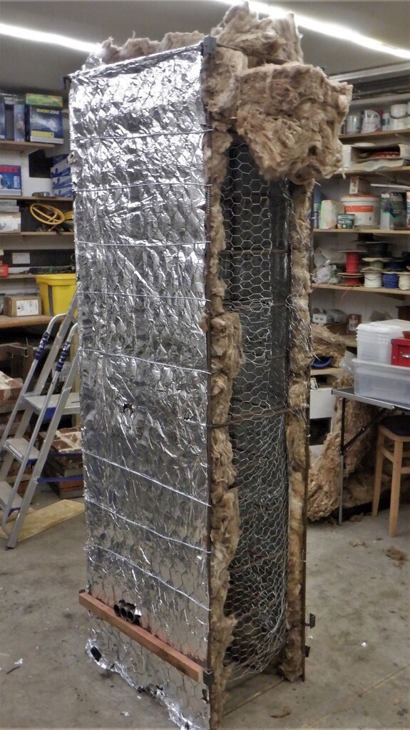
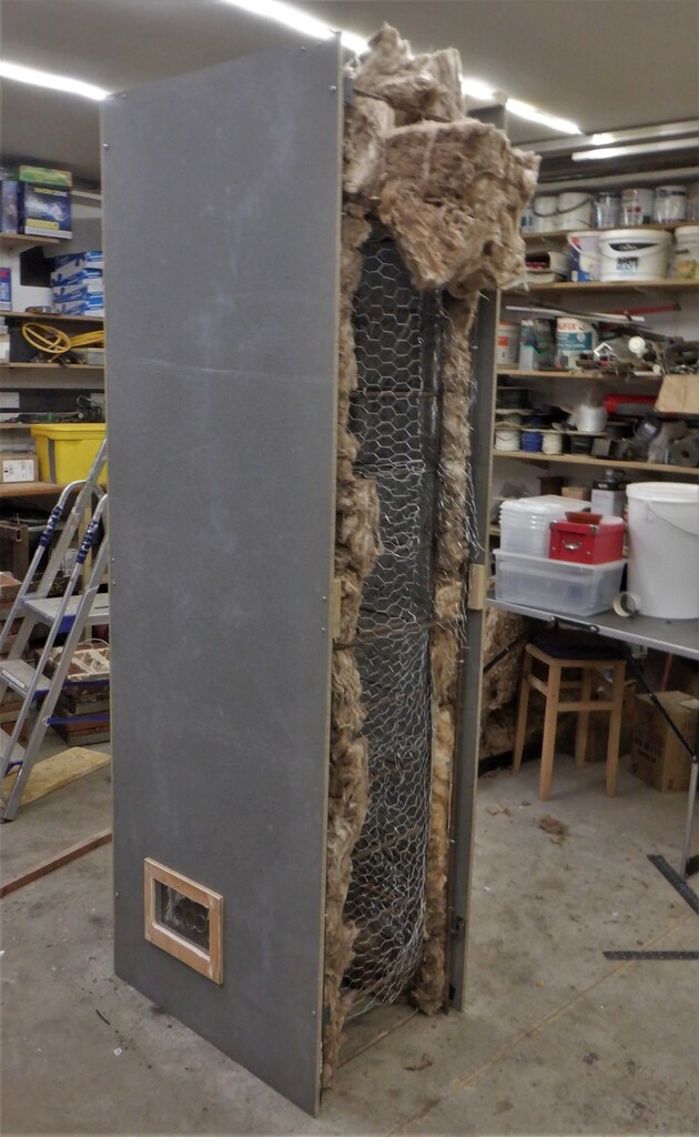
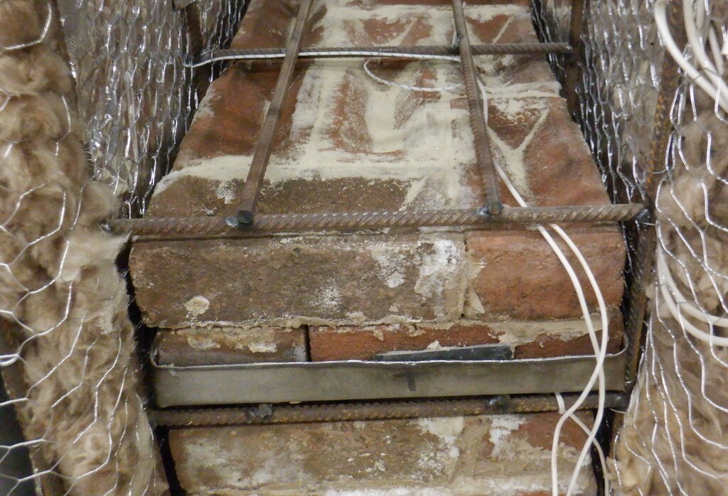
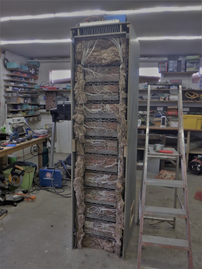
    The next job was to wrap the steel cage in chicken wire which will hold the glass wool insulation in place without it bending into the inner chamber and touching the trays of bricks. We needed an air gap around all the trays so that the hot air can rise and escape out of the top. We also laid across the chicken wire a layer of aluminium foil to reflect the heat back into the core. Finally, the glass wool, which was 50mm thick, was squashed into place with a second layer of chicken wire and another layer of aluminium foil. That is the basic design of the inner core.


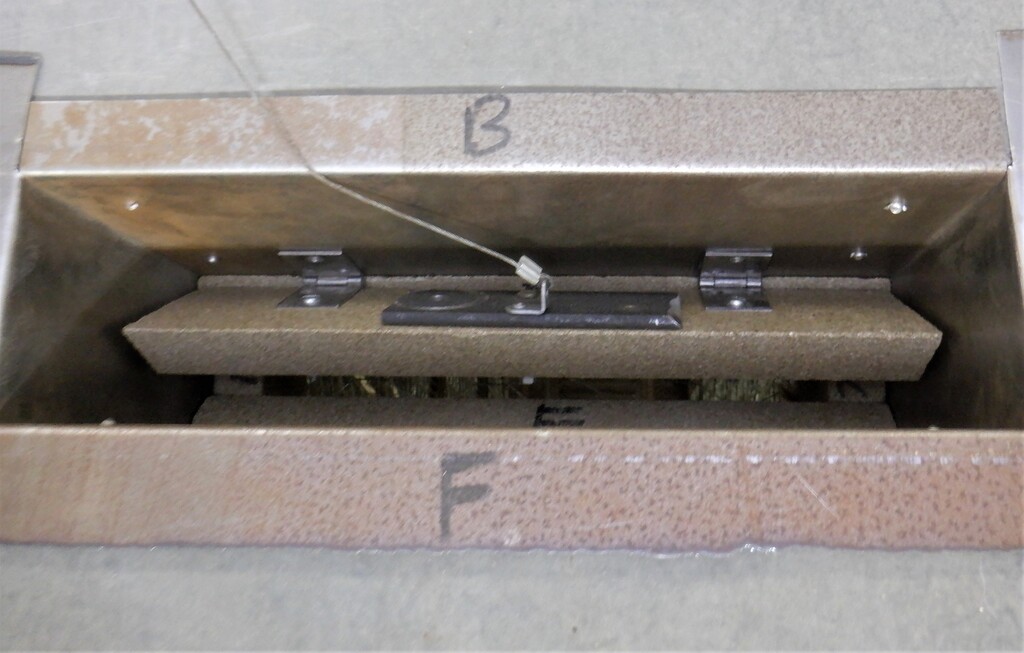
    The chimney at the top had an 1inch thick ceramic trap door which can be lifted up using a motor and let the heat out. The whole upper section is 150mm thick of glass wool to minimise the heat losses upwards and avoid overheating our electronic control board as well.


    The whole thing was then encased in a mixture of 10mm and 8mm thick cement boards to provide the final human safe outer cabinet shell. There is a small air gap between the cement shell and the insulated inner core, to allow fresh air to circulate up and around the whole unit and keep it cool.

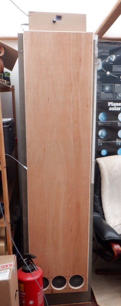
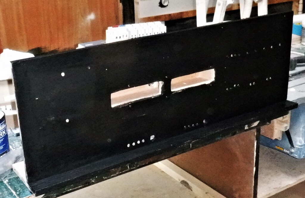
    The front panel then had a wooden duct built on it, to form a channel for the hot air to be vented out into the room around the floor level, using three high temperature rated case fans. They are speed controlled so can be adjusted electronically depending on various factors like room temperature, the chimney temperature and mixing chamber at the top. We would like to keep the temperature under control and not allow the shell to get too hot.

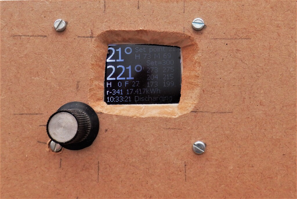
    The electronic control board has a little microcomputer that has lots of input pins connected to 9 different temperature sensors, 6 of them are high temperature thermocouples and the other 3 are the more normal types. We placed the thermocouples in and around the trays of bricks, three of them actually placed inside a brick, down a small hole and the other three are measuring the air temperature between trays, with one of them up in the chimney itself.

    With a combination of all the temperature sensors, we could control the heat output during the daytime by opening and closing the chimney and speeding up the fan to extract the hot air pouring out of the inner core. The control circuit also took the mains grid electricity during the night-time period and ?charged? up the ten trays of bricks, bringing them up to a working temperature of 300°C. Our calculations suggested that we should have been aiming for a much higher temperature of around 450°C to 500°C but we couldn’t get that far. There was too much heat loss out of the inner core, probably a lot of it is going up the chimney, even though the flap is fully closed. We discovered that it seems that our amount of glass wool insulation isn’t thick enough to provide a longer term heat storage.

    In hindsight, we probably should have gone for a smaller tray of bricks and put in twice as much glass wool insulation so we could have gone for a higher working temperature and be able to have a better control over the core temperature during the different periods of the year. On the other hand, it is working well enough to make a fabulous difference to our electricity usage during these cold times, and especially with us only paying 11p for a kWh unit of energy during the night 7 hours period, we are saving enormous amount of money this year. It doesn’t matter what the daytime prices are (actually it is 51p per kWh unit) because we don’t need to use any grid electricity during the daytime hours at all. Our battery is also being charged up during the 7 hours night-time period and we then can power our house from the batteries almost all the time. It is only during a rare occasion that we exceed the 5kW power capabilities of our powerful Solis inverter that we have to draw a little bit off directly off the National Grid.


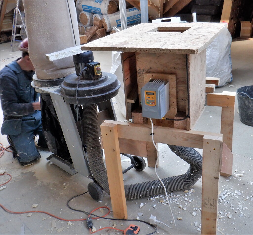
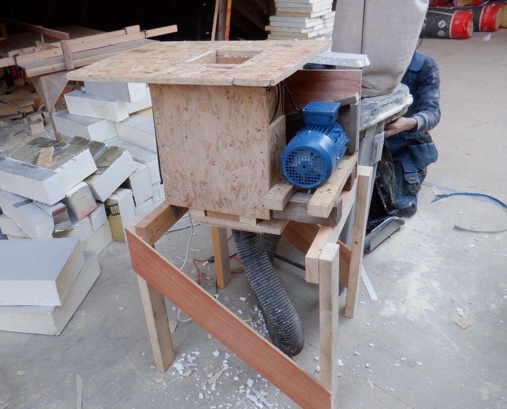
    We completely assembled the heater while still in the garage and did a test run of heating it up just in case something went wrong and burst in flames! First to only 200°C, inspect all side and check the temperature of the outside shell. As this was OK we started heating further and got to about 350°C and checked everything was again OK. The hottest outside parts only reached 50°C.

    Then the moment arrives when we had to install the giant thing into our living quarters. You may not appreciate this but this thing measures 550mm wide (nearly 2 feet), 750mm deep (2½ feet) and a massive 2100mm tall (7 feet) and it weighs, with all the bricks and everything, somewhere in the order of 500kg!! That is half a ton!! Smile!

    But of course, we couldn’t move 500kg! So we had designed it to allow us to undo the front section of the cabinet, undo the inner core and slide out the ten trays of bricks as well. We could then move the cabinet on a sack trolley into the long corridor of our living quarters and get it positioned into the correct location so that we could slide it into the hole we had made into the floorboards. We knew that 500kg would have been too much for our floorboards so we cut a rectangle segment out and put in some reinforcing wooden beams across the wooden foundations underneath. After a tricky time of moving the cabinet around and aligning it up to the hole, then slowly rotating it upright and at the same time, drop into this hole. We were just about clearing the ceiling but only just!! But we made it .. just ! Phew!

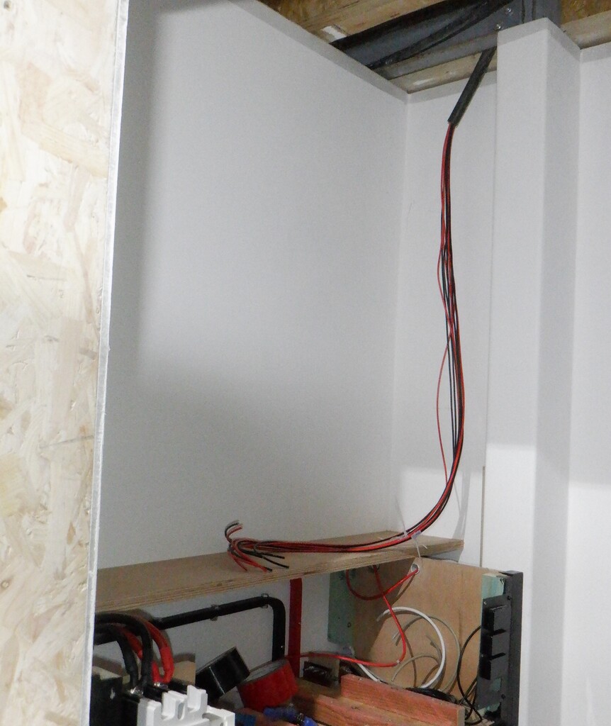
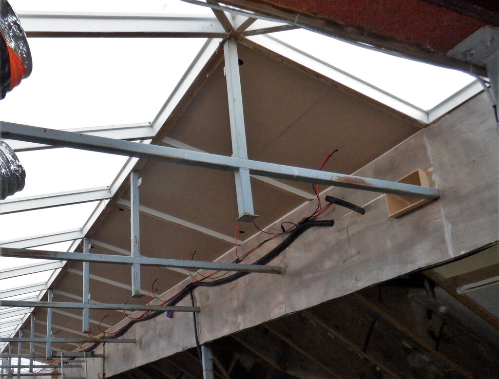
    We reassembled all the ten trays of bricks, redid the glass wool and chicken wire mesh to lock up the insulation again and then put the front panel back on. We laid in a new mains high capacity electric cable back to our consumer unit that we had to upgrade .. .. and switch it all on!!

    It works!!

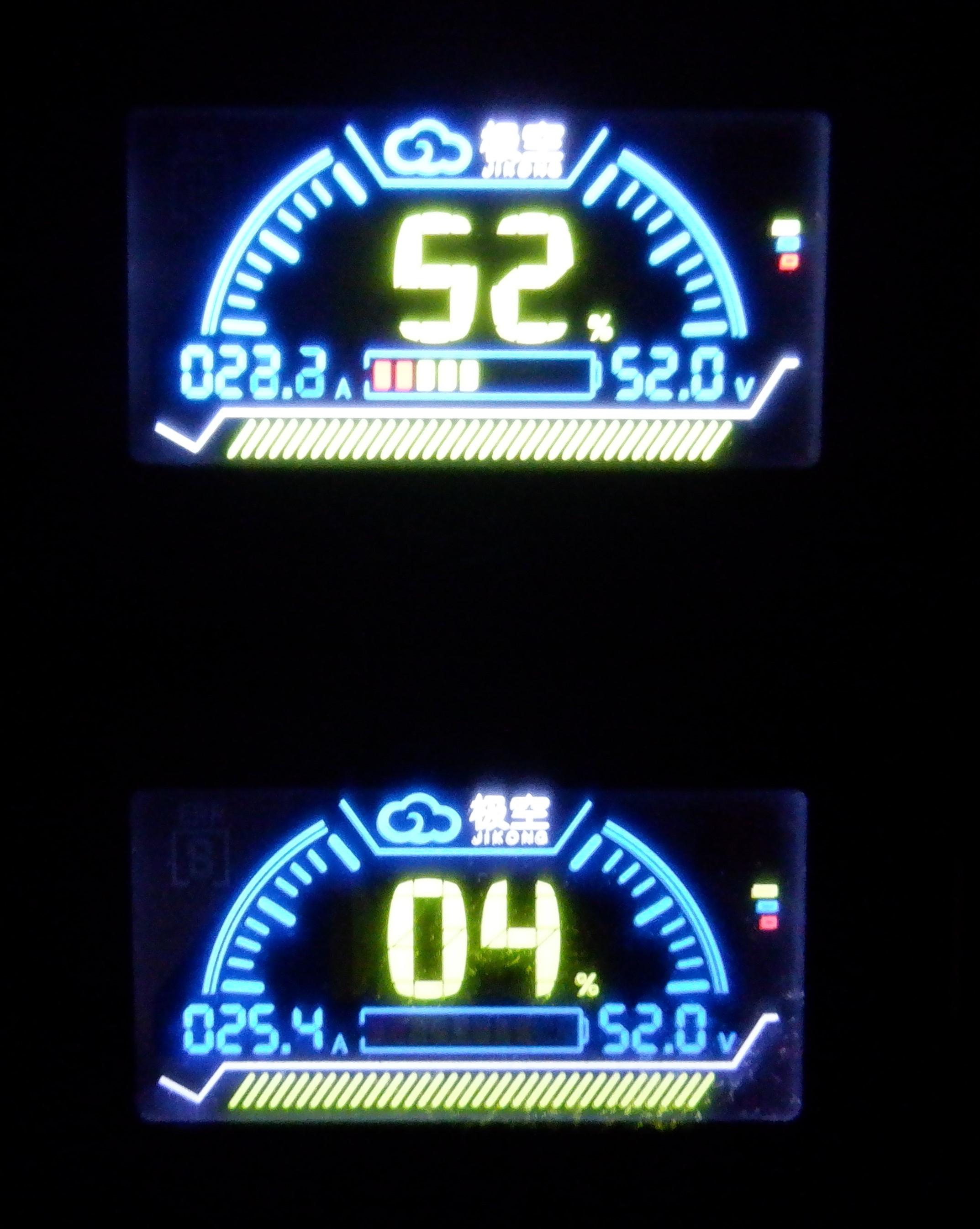
    As part of our new regime of working, we are doing a lot of computer work and this storage heater has some of the components of managing our equipment and communicating response packets back to our database. We record what the storage heater is doing during every minute of the day .. and night and we can see how the temperature of the various parts of the inner core is doing, and also, measuring what power we extract from the grid, plus what the fans are doing etc.

    We learnt to how control the fan speed during the different modes of operation, whether the flap is open or not and we must have reprogrammed the little microcontroller brains a dozen times with new functions and techniques to get what we wanted. It is still a working in progress but ..

    We have pretty pretty much finished all what we want to do to this storage heater. There may be minor adjustments as time goes past. But, now we are going to concentrate on getting our computer sorted and start working on the various software libraries for managing our whole house. We will resume our work on the house soon.


  • Adding Extra Insulation to our Roof on our Temporary Living Quarters

    Adding Extra Insulation to our Roof on our Temporary Living Quarters

    We were interrupted in doing this task by a bout of Covid and waiting for the weather, but we finally got to install an extra layer of insulation foam boards to the roof of our temporary living quarters. We are suffering from the huge rises in electricity prices and we needed to do something about it and save money.
    So we decided to make use of our recent supply of recycled PU foam board pieces and construct 90mm thick panels. We took a heap of random sized pieces, only making sure that they were at least 1200mm wide and put them through the slicing machine to make 90mm wide pieces. We then stacked them into a frame and stuck them together with a little bit of PU spray glue. We stacked them up to a height of 1750mm which covers the majority of the roof surface, leaving a small gap down the ridge line, which will be filled in with other 90mm pieces later on.

    Adding Extra Insulation to our Roof on our Temporary Living Quarters

    Sliced-insulation-glued-into-a-sheet


    We proceeded to make sixteen of these panels over the course of several days.
    Adding Extra Insulation to our Roof on our Temporary Living Quarters

    Constructed-sheets-ready-for-install


    One of the early jobs we did before we got Covid, was to install a series of 89mm CLS timber pieces up on the roof so that we had somewhere to fit down the roofing felt and also retain the foam panels in. These CLS pieces were screwed down with 150mm screws, all the way around the edge.
    Adding Extra Insulation to our Roof on our Temporary Living Quarters

    Temp-Living-extra-insulation-framing


    The next task was to slice up some 11mm OSB board to generate fourteen 100mm wide strips and four 75mm ones, all them being 1780mm long. These pieces will be used to clamp down the insulation panels. Eventually, we will laid down a covering of protective roofing felt, so we decided that these OSB strips needed to have their edges chamfered so we put each one through our router. The four smaller strips had a quarter round shaped on one edge and a 45degree slope cut into the other edge. The same 45degrees chamfer was done on both edges of the other fourteen strips.

    Then, after ordering a box of 180mm long screws and clout nails for the roofing felt and grabbing a lovely clear day today, we managed to get all sixteen panels up onto the roof, starting at the far end and proceeded to fit each one, sometimes needing to trim them down a little bit and clamping the edges down using the strips of 11mm OSB we made earlier. We had to drive the long screw into the roof, to seek out the old 50mm roof rafter inside the structure, and making sure we found it so we had a solid fixing.
    Because the old roof had regular slight hollows, we used lots of spray PU foam to fill this little gap between the new insulation panels and the old roof surface, in order to support the new panels, especially when we walk over the new roof whilst applying the roofing felt.

    Adding Extra Insulation to our Roof on our Temporary Living Quarters

    Foam-under-the-sheet-to-fix-and-support-tehm


    We managed to get the entire roof covers by about 4pm and the last job to do was to cover this new covering with a tarpaulin, to make sure that the majority of the rain will be deflected away and keep it reasonably dry. The weather is very wet at the moment and we need to wait until we have a full dry day to get the final roofing felt glued and nail down.
    Adding Extra Insulation to our Roof on our Temporary Living Quarters

    All-boards-installed


    Now we wait …
    We finally got the roof felt on a week later! It was the first dry day when we did not have other commitments, it turned a to be a very drear day with fog all day.
    The felt was rolled onto the roof and nailed around the perimiter and along the OSB fixing strips as well as gluing it to the roof at the overlaps and gluing the overlaps to them selves.
    Adding Extra Insulation to our Roof on our Temporary Living Quarters

    Covering-the-insulation

    Adding Extra Insulation to our Roof on our Temporary Living Quarters

    All-covered


  • Covid Strikes Workforce!!

    Sorry to say but we have to struck down by the Covid virus!! We think it arrived from when we visited the hospital, which then got passed on to the rest of the family. One way and another, we lost about 16 days of work.
    We are now fully recovered and have no signs of any lasting effects .. thank goodness!!

  • Installing Third String of Solar Panel up Inside Skylight

    Installing Third String of Solar Panel up Inside Skylight

    We started the new week by tackling the next phase of installing our green solar capture schemes, this time, the third string of panels, basically almost square shaped ones, measuring 1200mm by 900mm, small enough to fit up inside our eleven Skylight windows. Each of these windows which we had originally designed 10 years ago, measures 1040mm wide by 1200mm high. We had always intended to have solar electric cells put in these windows. We had originally inteneded to make our own solar panel from individual cells, but we realised that we could buy fully constructed panels for a reasonable price not much more than the raw parts, plus also we would not have to run the risk of not being able to make long lasting and reliable finished modules either.
    The first job was to measure all eleven windows and most of them were 1040mm wide, but one or two were slightly bigger and one or two were even a little bit smaller (measuring 1034mm wide). Then, we thoroughly washed the glass (actually polycarbonate plastic) with warm soapy water with a floor mop! We also washed down the framework too so it is ready for the glue to stick down the CLS timber we are going to apply.
    We then cut twenty-two lengths of 63mm, measuring 1195mm long CLS timber, with a 15degree angled ends and drilled two clearance holes through the wider direction in each piece. We applied a line of glue and proceeded to screw each piece using 100mm 6mm thick screws. This CLS timber will provide the anchorage for holding the actual solar panel themselves in place.

    Installing Third String of Solar Panel up Inside Skylight

    Skylight-solar-panel-frame


    The CLS timber will almost fill up the gap and block the sunshine from getting through to the insulation boards that will sit behind each solar panel, leaving a small gap that we will allow the air to circulate in and around the panel to keep it cool and ensure that we evaporate any condensation of water that may form on the glass. Each of the eleven window with its solar panel, will have fresh air piped in from our main air conditioning system so we can provide some cooling energy to the panel themselves, especially during the hot Summers, which will improve the efficiency of the silicon wafers converting the solar energy into electricity.

    We then put small pieces of double sticky foam on all four corners of each solar panel modules, sticking 100mm long pieces onto the metal frame and this will provide a reasonable air gap between the panel and the glass surface, and also we drilled three holes through the metal framework on both sides of each panel sideways, so we can screw the panel in place, using our mushroom headed stainless screws, up in the Skylight window and press up against the plastic surface. We even stuck on two small pads of 6mm MDF material so we ensure another air gap at the top of the panel, again to allow the air to circulate etc.

    Installing Third String of Solar Panel up Inside Skylight

    Most-skylight-panel-fitted

    Next task was to plumb in a conduit from inside our Tech Cupboard, up into the ceiling, through the floorboard, up the steel leg and terminate right up inside the Skylight near the top.
    This will provide the path for our five pairs of 2.5mm square millimetre copper wires, coming from the eleven Solar Panels, grouped into five sets. We decided that we will have a sequence of one panel on a pair of wires, then followed by a group of four panels joined together in series and connected to another pair of wires. After that one, is another single panel on a third pair of wires, followed again by another group of four panels on the fourth pair of wires and finally the last single panel on a fifth pair of wires. All the wires were fed up from inside the Tech Cupboard and went off to each of these set of panels.

    Installing Third String of Solar Panel up Inside Skylight

    Skylight-solar-cables-in-Tech-cupboard

    We did it that way so we could configure different combinations of connecting the panels together, to provide the maximum conversion of solar to different target battery voltages. We are wanting to charge our 12Volt battery but also want to charge our 50Volt packs too. in fact, for the time being, we would like to take all the output of all eleven solar panels if it is possible and convert all the energy into our 50Volt packs and maximise the benefit of avoiding having to pay these ridiculous grid electricity prices.

    Now we needed to make a front panel to mount the solar charging equipment, the switches and the fuses too. We found a piece of plywood left-over piece from when we were doing the staircase, a lovely quality of 18mm plywood, measuring 345mm wide. We sliced off a length of 1070mm long so it can fit right across the Tech Cupboard, mounted in a vertical direction and facing outwards, and sitting on top of the Battery Cabinet. This front panel will have a distribution fuse box starting on the left end, to provide low-voltage (both 50V and 12V) fused protection for various pieces of equipment in our Tech Cupboard like network hubs and fileservers etc. Then are the two solar charger modules next on the front panels and finally another distribution box that will have two isolation switches and more fused connections coming from the solar panels themselves. We drilled a load of access holes to allow the various wires through to join into these modules. We also sliced two rectangular narrow slots behind the two solar chargers, to allow fresh air to blow on the cooling fins that runs top to bottom on the back of the units.

    We also took the lid of the Battery Cabinet, which we hadn’t processed yet, and cut that down to size to fit in between the walls and the steel leg. We decided that we needed to also slice the whole lid in half, down the length so that we had a more permanent section at the back and still have the front half removable for any future adjustments or modifications inside the Battery Cabinet itself. Our new front panel will sit on the back shelf piece some 50mm inwards and is screwed upwards to join the two pieces together.

    Then, we painted all three pieces in our black paint to match the rest of the Cabinet.

    Installing Third String of Solar Panel up Inside Skylight

    Solar-Equipment-panel

    While the paint dries, we got on in making covers to put over the new Solar Panels up in our Skylight so that we both keep the dust out, but also, to provide a sealed chamber so we can pump in fresh cool air at the bottom of the window and suck the warmer waste air out at the top. These covers are made using 6mm MDF sheets, cut down to just fit inside the Skylight rafters, the height being 1210mm long and the width being set to 1030mm as a minimum so it can fit in all the skylight windows. Two 50mm air holes were drilled into the left bottom corner and then diagonally at the top right corner and also we drilled two 20mm holes in the lower middle point to allow the electric cables to come through from the Solar Panel. We found that it is a tight squeeze to get these covers in place so we decided to slice every board in half and it was so much easier to tackle the problem of installing these covers. Each had three screws put in on each edge. Finally, we covered up the holes with aluminium tape and also sealed the bottom and top edges with a line of spray foam so we keep the dust away from the solar panels.

    Installing Third String of Solar Panel up Inside Skylight

    Skylight-solar-cover-panels-fitted

    Finally, we wired up all the equipment that now have been mounted to our freshly painted front panel, connecting the five individual groups of the solar panels into the switch bank and then wired in the isolation switches from the solar chargers themselves. We then installed this front panel on top of the Battery Cabinet and screwed it into place and connected it to the 50Volt bus bar, plus also all the cables coming down from the Skylight were connected into the top side of the bank of switches. We now have a working third string of solar panels!

    Installing Third String of Solar Panel up Inside Skylight

    Solar-Eqipment-fitted

    Installing Third String of Solar Panel up Inside Skylight

    Skylight-solar-charger-working


    Today, we collected 4kWh worth of energy but we do need to go outside and climb up onto the roof, to clean the Skylight windows as they have several years of accumulated grime. We will do a test of cleaning half the windows and then flip between the two halves and find out how much difference it might make to our Solar power collected.

    That pretty much concludes everything to do with our Solar, the electrical version for now, we got a thermal one to tackle sometime in the future. We will now get on with installing extra insulation into our temporary living quarters, to help reduce our electricity burden!

  • Installed Second String of Solar Panels Up on P Roof

    For this week, since we have built the two battery 50Volt drawers, we decided to get on with installing the second string of Solar Panels, up on the P section of the Roof, which faces the Sun during the morning hours. We didn’t start until Wednesday, removing and cutting the slates for each metal bracket position and proceeded to mount eight brackets for the first row of two Solar Panels, then another eight brackets for the next two Solar Panels and then finally ten brackets for the third row of three Solar Panels, situated up near the top of the sloping roof.
    We used lengths of timber screwed to a completed line of brackets, to afford us some safe footing as we worked our way up the roof.

    Installed Second String of Solar Panels Up on P Roof

    P-All-Brackets-


    We also cut the aluminium bars into three completed sets, two approximately 3900mm long and the third set 5500mm and then painted the various parts which will be exposed, in a black colour, to blend with the dark slates.

    Then on Saturday, we took up our newly painted aluminium bars and started at the top row, mounting the horizontal bars across their five brackets and then brought up three Solar Panels and clamped them down to the bars, connecting up the wires etc. We did a quick electrical test by connecting the trailing cable to the third panel and went indoors to our Utility Cupboard to measure 118Volts coming out the other end which is very good. We then, after lunch, repeated the same process for the second row, this time, two Solar panels, and then finally the third bottom row with two more Solar Panels, doing the same electrical test for each row completed and all was just fine.

    Installed Second String of Solar Panels Up on P Roof

    P-Solar-Panels-installed


    It was a very hot day in full sunshine and hardly any wind to cool us down! Phew! But we now have seven more Solar Panels installed and connected to our Solis Inverter box, generating another 2.8kWatts maximum during the earlier hours of the day.
    The final task of the day was to disassemble our working platform that helped us get on and off the roof, the two platform modules had their legs unscrewed and stored back in the Swimming Lane for another occasion and the two flat tops were also stored in the lane too. We now have a cleared path all the way around the house. Lovely!

    Update: Sunday was a lovely day and after a cloudy start the rest of the day was almost perfect. The P roof started generating a usefull amount of power at 8am and by 9 was going strong. It peaked @ 2.68kW (96% of Max) about 11am. The Total output peaked at 1pm @ 4.86kW and the combined system generated more than 28kW hours of energy. This is enough to charge the battery by over 18kWh.

  • Early Results of Running the 50Volt Battery Packs

    We decided to allow our 50Volt battery packs to run more empty by changing the lower threshold point that they are allowed to discharge down to before cutting off and we left them to run overnight.
    On the morning, we discovered that both battery packs had switched themselves off and upon examining the status of each pack, found that Pack One has discharged down to the minimum voltage threshold as expected but for Pack Two, we discovered that one particular cell, number 6, had drained to the cut-off threshold faster than its siblings and the the computer is programmed to disconnect the whole pack if it discovers any of its sixteen cells has fallen below the safe voltage levels, which is exactly what has happened. This is very useful to know this weakness and we are planning to swop out this cell for one of the 12Volt cells as we are unlikely to put the 12Volt pack through such heavy demands as we will be putting the two 50Volt packs.
    But, in the meantime, we programmed the Solis Inverter to go into deliberate charging mode, using the Grid supply, to boost the charge levels back up to more useable levels. We also had a glorious sunny day on Thursday and we had collected 16kWh of energy and all of it was pushed into our battery packs, along with about 7kWh of Grid electricity before we told the Inverter to halt the charging operation at 6pm when we finished work.
    We decided that we won’t allow the batteries to drain so far down to that shutdown threshold again so we reprogrammed the Inverter to stop drawing on the batteries when the voltage dips below 48Volts, which should allow the batteries to provide a tickle of power to the Inverter which will continue to monitor what our household is using and keep a record of our electricity usage at every 5 minutes intervals. The batteries look a bit better now that they had a good charge but we will wait and see and probably will deliberately discharge the two packs again and see what happens, especially to cell number 6 again.

    We had another lovely day on Friday and we collected almost another 10kWh of energy but we will have to continue in our designed implementation of providing night-time grid charging and sign up to those off-peak tariffs to take advantage of loading our battery packs full of cheap electricity and run the household fully from the batteries instead, because even though we collected nearly 10kWh from the Sun, we actually consumed 25kWh for our whole 24hour period. It is going to get worse as the Sun moves around into the Winter cycle so we definitely will need to tap into the cheap electricity being offered during those off-peak hours.
    Even with the second string of Solar Panels that we are currently installing, may give us another 5kWh on this particular day but of course, it could go much lower than that on a very dreary cloudy day, but also generate a load during a very good sunny day. This is why we are going to be building a Green Computer system that will monitor the weather for the next 24 hours, also monitor the electricity prices (so we can take advantage of those special cheap rates, even negative rates where they will pay YOU money to use the Grid electricity) and manage the whole battery packs, its chargers and the various solar inverters too. We will even eventually include the Thermal Solar arrays that we will have on our Garage roof, heating up water from the sunshine, and have that source of Solar Energy incorporated into the Green mix.

    Early Results of Running the 50Volt Battery Packs

    50V-Battery-displays