Blog

  • Third Battery Drawer Assembled, The 12Volt Pack

    Our third drawer, the smaller one, had the remaining four battery cells installed and wired up. We swopped out the isolating switch for a heavier duty model, capable of handling up to 100Amps. It is now ready to be installed into the cabinet itself.

    12V Battery Draw

    12V Battery Draw

    Third Battery Drawer Assembled, The 12Volt Pack

    12V-Battery-draw

    Third Battery Drawer Assembled, The 12Volt Pack

    12V-Battery-connections


    We got one more drawer which is empty at the moment but we may invest in buying some more cells next year if we deem that it would be useful and help us capture more Solar and cheaper electric rates during the off-peak periods. We also will wait until the pound grows a bit stronger again as we have to buy the equipment in American Dollars!!

  • Construction of Battery Cabinet

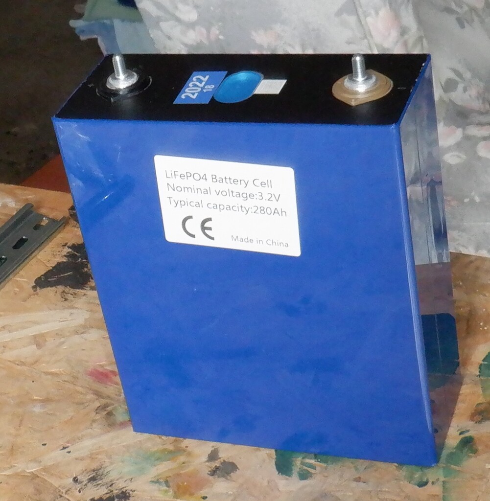
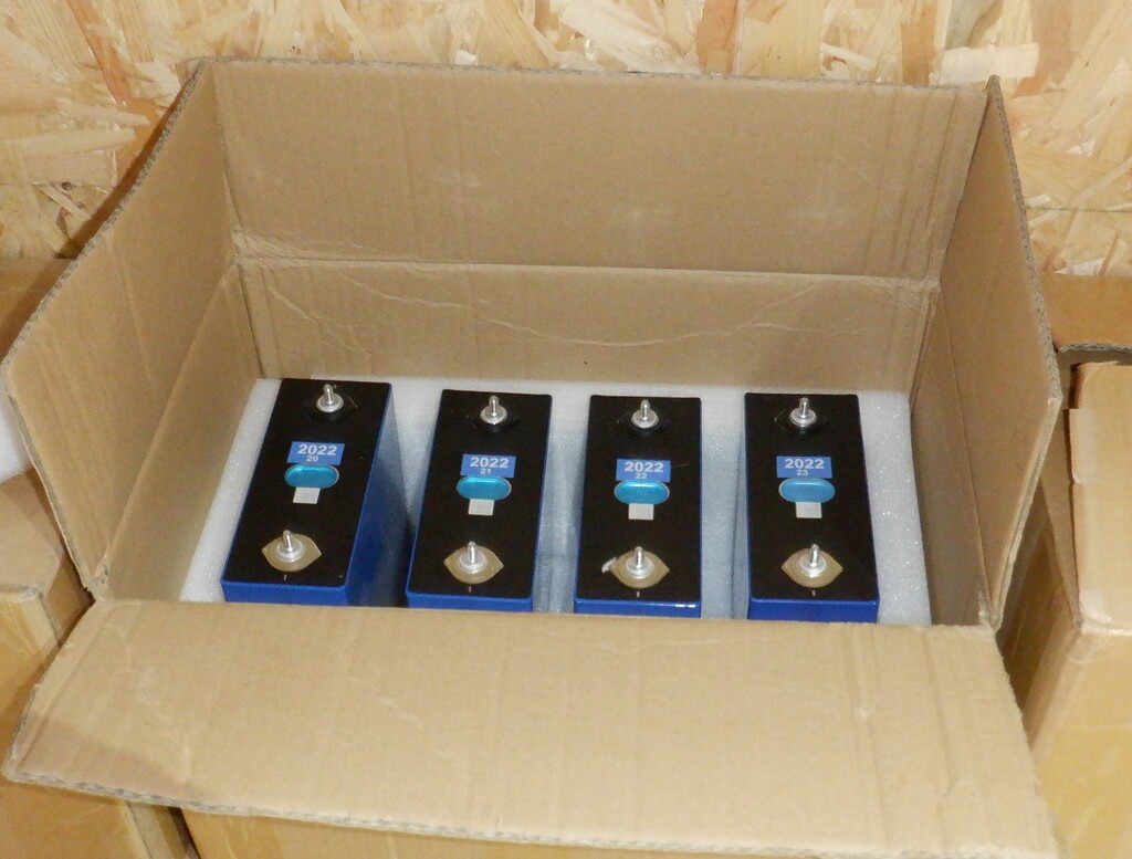
    We spent the last week or so, constructing a cabinet to hold all our Lithium Iron Sulphate cells, grouped into battery packs. We went for a drawer design so we can access the individual cells but have them safely tucked away from fingers or metal objects.
    The basic overall dimensions of this cabinet is 900mm wide and 400mm deep, with the top outer “lid” about 1300mm off the floor. There are four drawers all together, three being 295mm tall to store the 50Volt battery packs and one drawer being 165mm tall to store the 12Volt pack. Then a 250mm tall shelf with a front panel that will have the display modules to show the status of the battery packs, mains powered chargers with their own cut-off switches and finally a master cut-off switch for the whole cabinet.
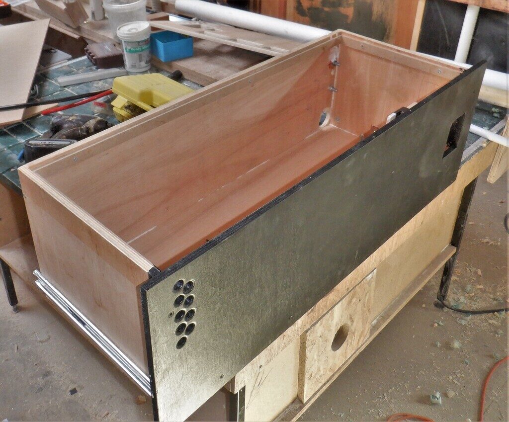
    We used a complete sheet and a narrow strip off another second one of our 12mm thick posh plywood material, to slice all the parts for the four drawers, we put all the dimensions of each piece into an optimiser and it told us where to slice, to minimise wastage. We used a combination of our track saw plus also our table top circular saw, to slice the sheet up into consistent size pieces. We then cut a groove in the four vertical sides of each drawer so the base board will be well supported and take the weight of the battery cells, as the sixteen cells that makes up the 50Volt packs will weigh almost 100kg in total. We had to order heavy duty drawer runners to cope with that kind of load.
    We then started drilling and cutting out the various air holes and cut-outs for the switch on the front panel, and then cable access at the rear of the drawers including installing metal bolts and metal brackets to hold the computer etc.
    Next, we put on the drawer runners themselves, three heavy duty ones for the big drawers and a single medium duty runner for the 12Volt drawer which has only four cells in it weighing just over 20kg.

    Construction of Battery Cabinet

    A-Draw-


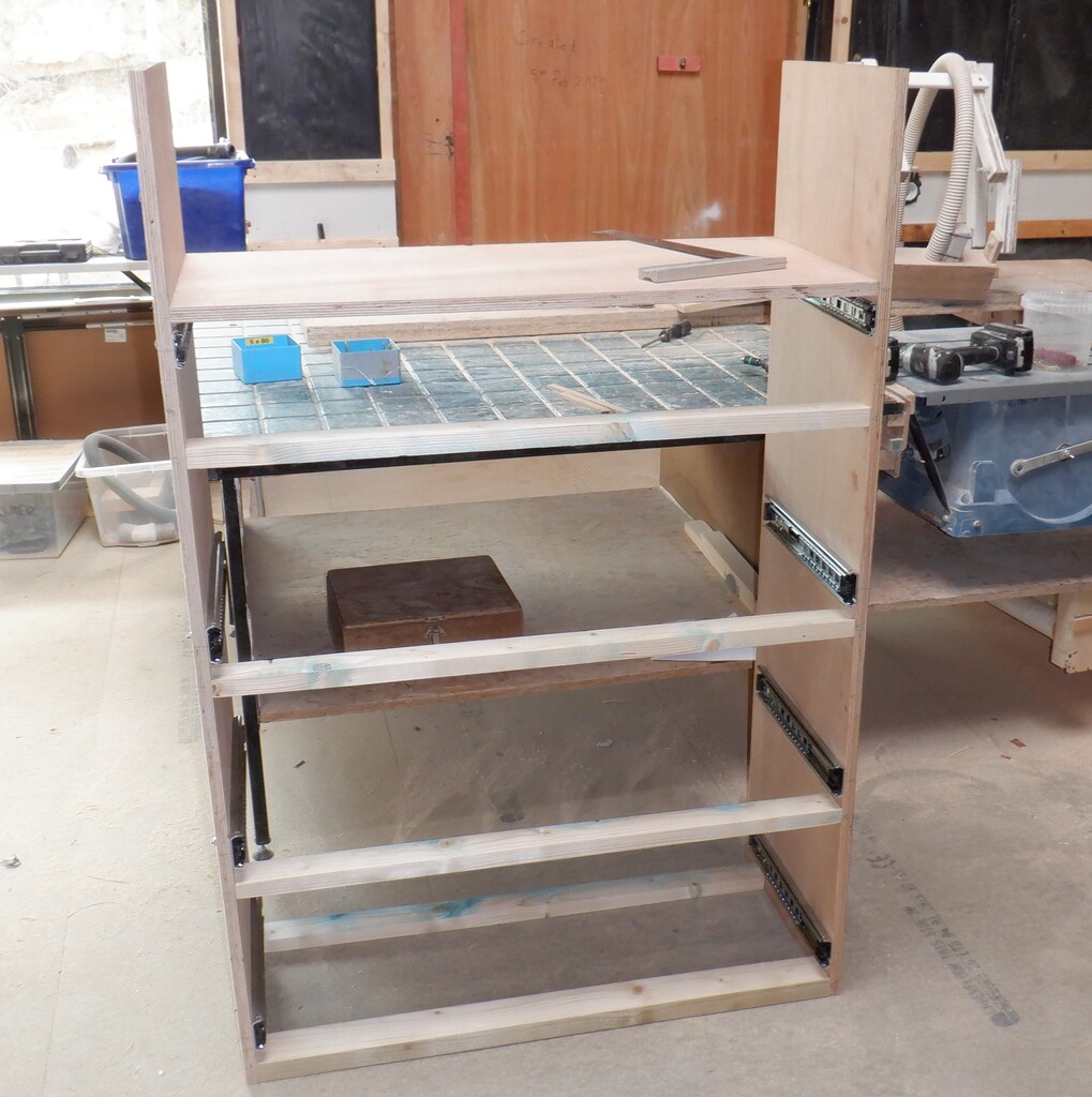
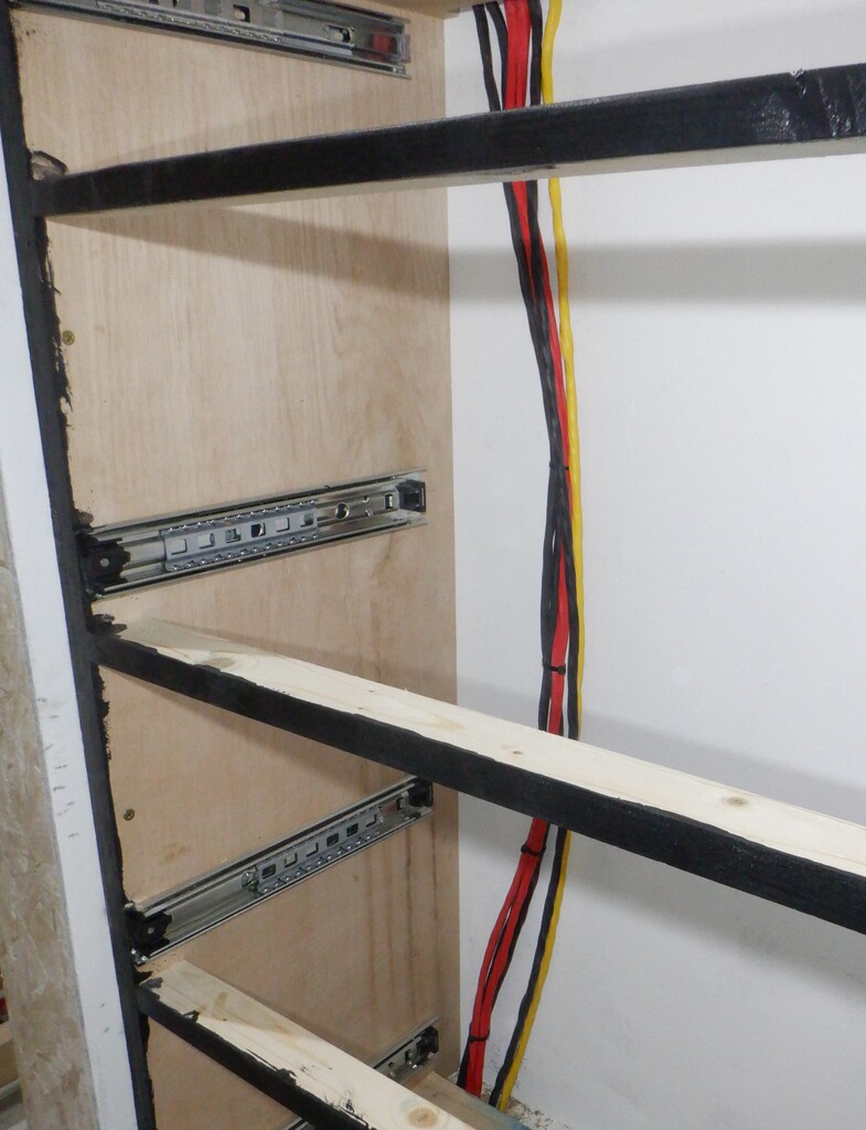
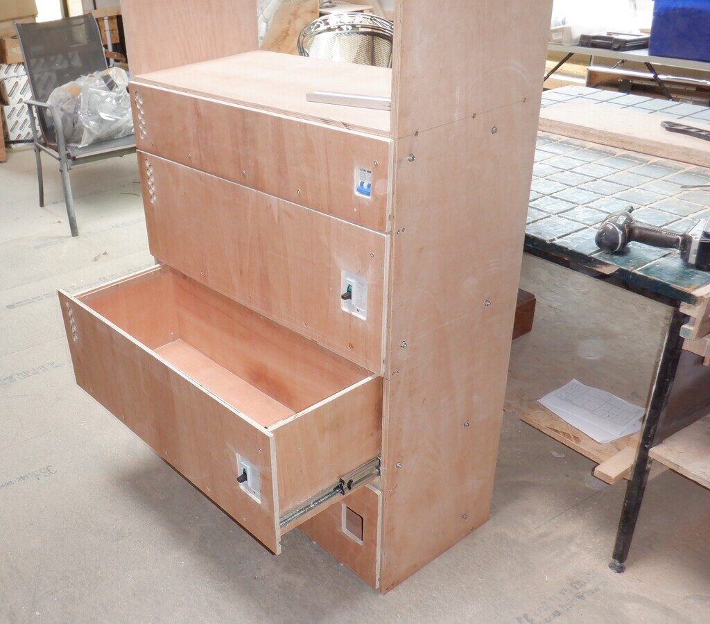
    Now we got a sheet of 18mm thick plywood out of our sheet storage room and proceeded to slice that up into 400mm wide strips to create the cabinet itself. We needed to make sure that one piece is long enough to bridge right across the Tech Cupboard, this forming the top surface of the cabinet, which measures 1085mm wide. This means that the remainders can form the vertical sides where we then installed the other half of the runners in their assigned positions so that the bottom drawer is 30mm off the floor surface and then a gap of 5mm between drawers plus another 5mm gap to the top shelf that will have a fixed front panel that has other equipment and modules including computers and master isolating switches too.
    Construction of Battery Cabinet

    All-draws-fitted


    Now that we have the drawers in place, we could put in reinforcing horizontal bars to help stabilise the sides and also provide a visual and physical blockage between the drawers, so we used pieces of 50mm by 25mm battens which we planed down to make them smoother. We put two at the bottom, one at the front to complete that blockage strip, but a second one near the back to lock the back edge together. Finally, we took the fourth piece of our 18mm plywood 400mm wide left-over strip and cut that down to the internal dimensions, 862mm, and fitted that in place so that it provides the same blocking function as the other battens. We now have a rigid and fairly robust cabinet with a shelf which forms the complete storage for holding our battery packs and all the electronics for charging and monitoring everything.
    Construction of Battery Cabinet

    Cabinet-built


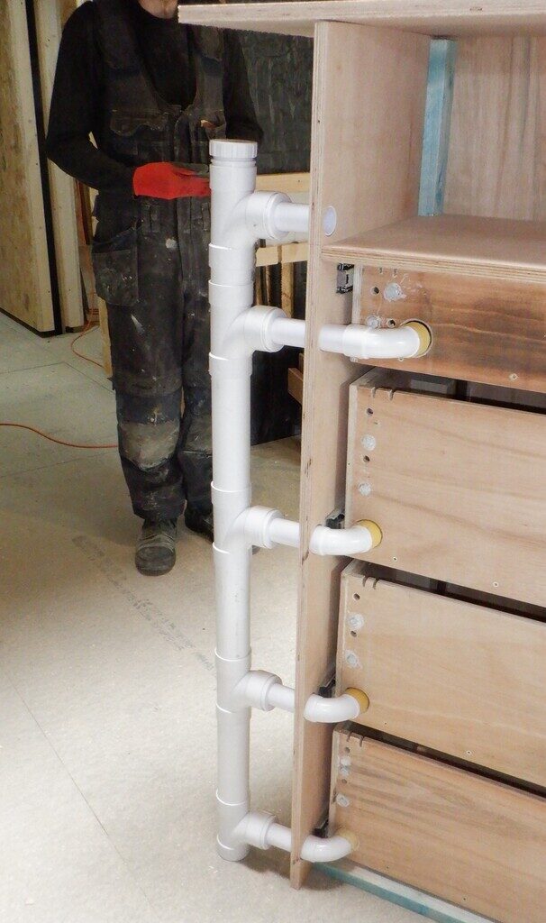
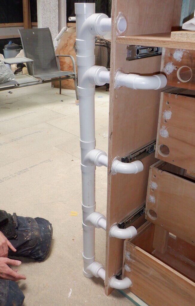
    We then turned the cabinet around so we could work on fitting an air duct to each drawer, to provide active cooling to make sure the system runs cool. We installed a vertical stack of 50mm wide plastic pipes with a series of T-junctions pieces with adapters fitted so we can have 32mm plastic pipes coming out sideways and have a sweep bends to enter into the back of each drawer. We got it just in the correct position so that a drawer can open and shut so that the ends of the pipes fits neatly in place and blow air inside the drawer. We assembled the pieces and then test fitted the whole cabinet into the Tech Cupboard, to make sure we could move it through the doorway and into the correct location on the left side of the cupboard which includes going around the metal Skylight leg too. It was successful so we proceeded to permanently glue the plastic into place using our PU construction glue which forms a very tough solid bonds.
    Construction of Battery Cabinet

    Air-supply-yo-the-draws

    Construction of Battery Cabinet

    Air-ducts-glued-in-place


    Next, we started mapping out the electronic equipment that will live on the shelf, including creating another front panel to cover the whole shelf. This being the fifth front panel move, above the four drawers. It had cut-outs for two master switches on the left hand side, a row of four rectangular cut-outs for the mains powered 50Volts chargers along the bottom (they are sitting on the shelf itself) and a display panel that will have four individual little displays showing the status of the four battery packs, this panel is located on the right side. then, each of the chargers will also have their own little display showing the voltage and current measurements of each charger. Finally, there is the usual air holes on the left side to allow the waste air to escape back into the Tech Cupboard and drawn away up in the ceiling.

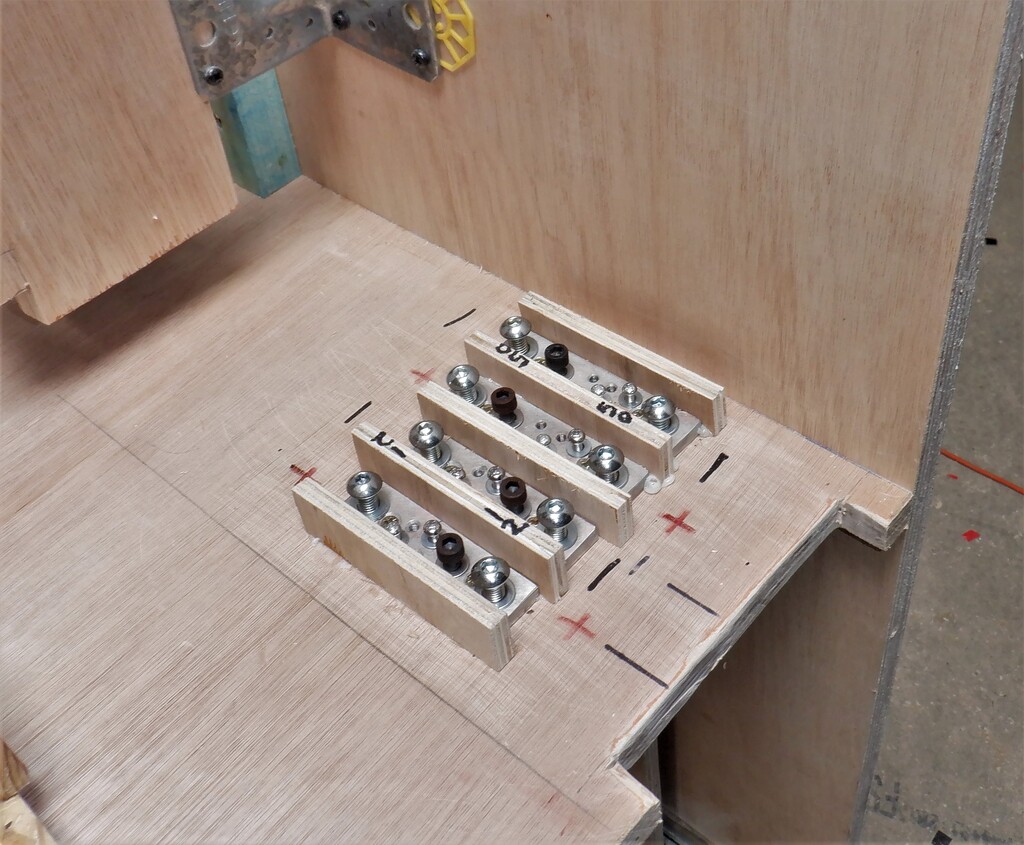
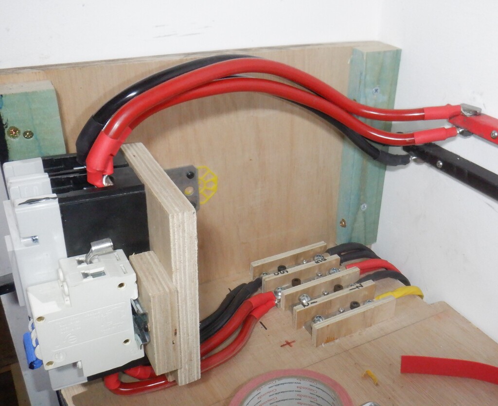
    One of the other jobs we did for this shelf, was to make bus bars and terminal blocks so that we could bolt on our heavy duty electrical wires and manage the connections inside the cabinet. We made four solid copper terminal blocks, measuring 100mm long by 25mm wide, and then drilled various holes into this 8mm thick bar which we then tapped a screw thread into the material so we could bolt down the tags that are crimped on to the ends of the various wires. We put a vertical small piece of plywood between each copper block so that they are isolated from each other, to avoid accidental shortages etc.

    Construction of Battery Cabinet

    Internal-distribution-blocks


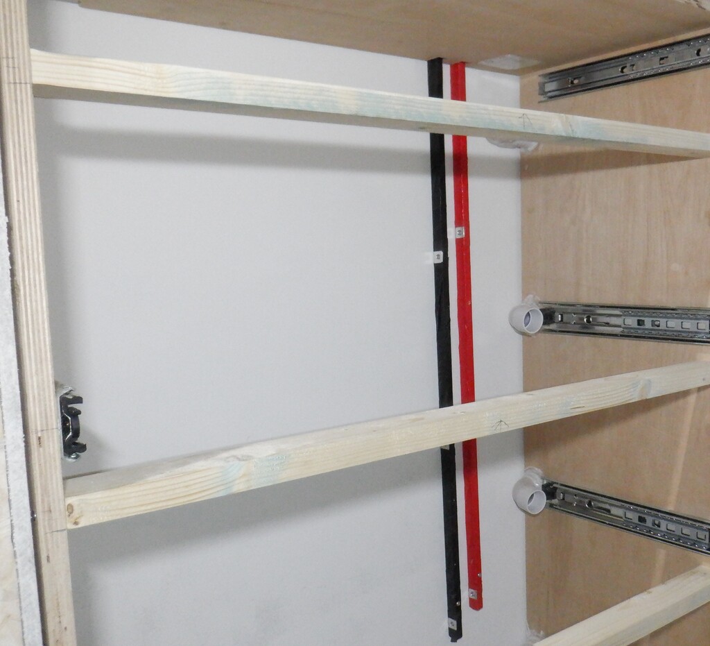
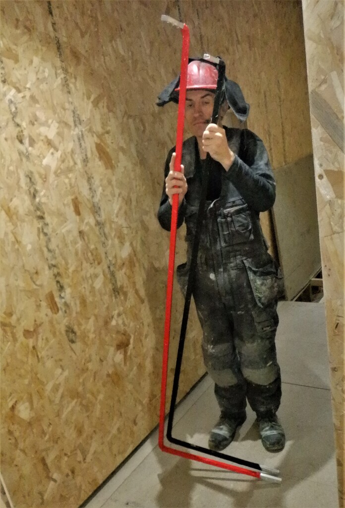
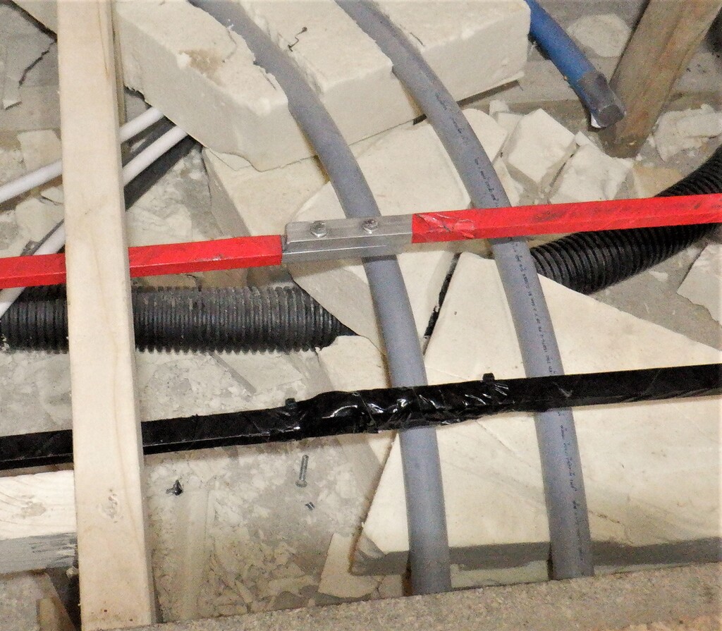
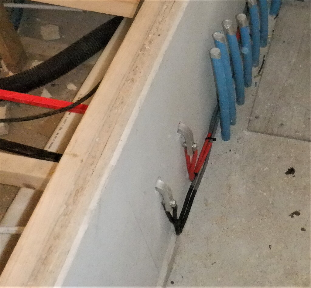
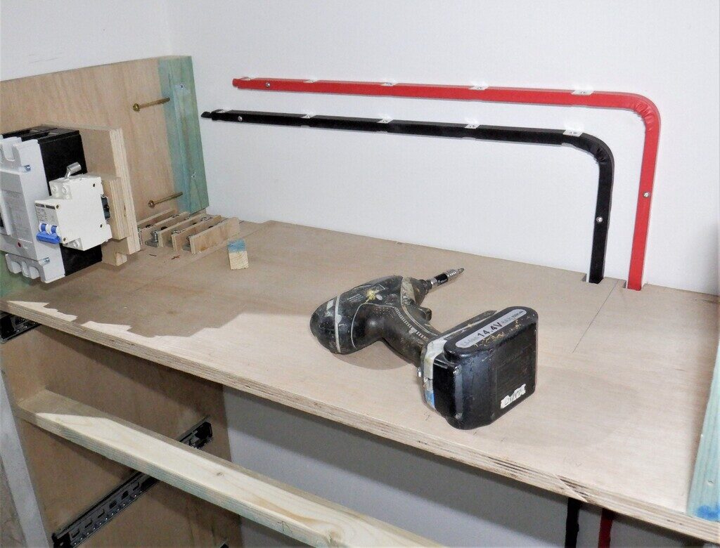
    Then we took two length of our aluminium bars 1700mm long, and drilled a whole collection of holes to provide more connection points, to and from, various chargers and to each 50Volt battery packs in their drawers. We bent the bar at the 600mm point so that it can be screwed to the wall of the Tech Cupboard where the cabinet is located and provide a high powered transfer of the 50Volts supplies inside the cabinet and send it out to the wider world via the master cut-off switch.

    We wrapped them up in red and black tapes but also slid on some giant heat-shrink tubing to provide a robust protection against electrical shorts on top.

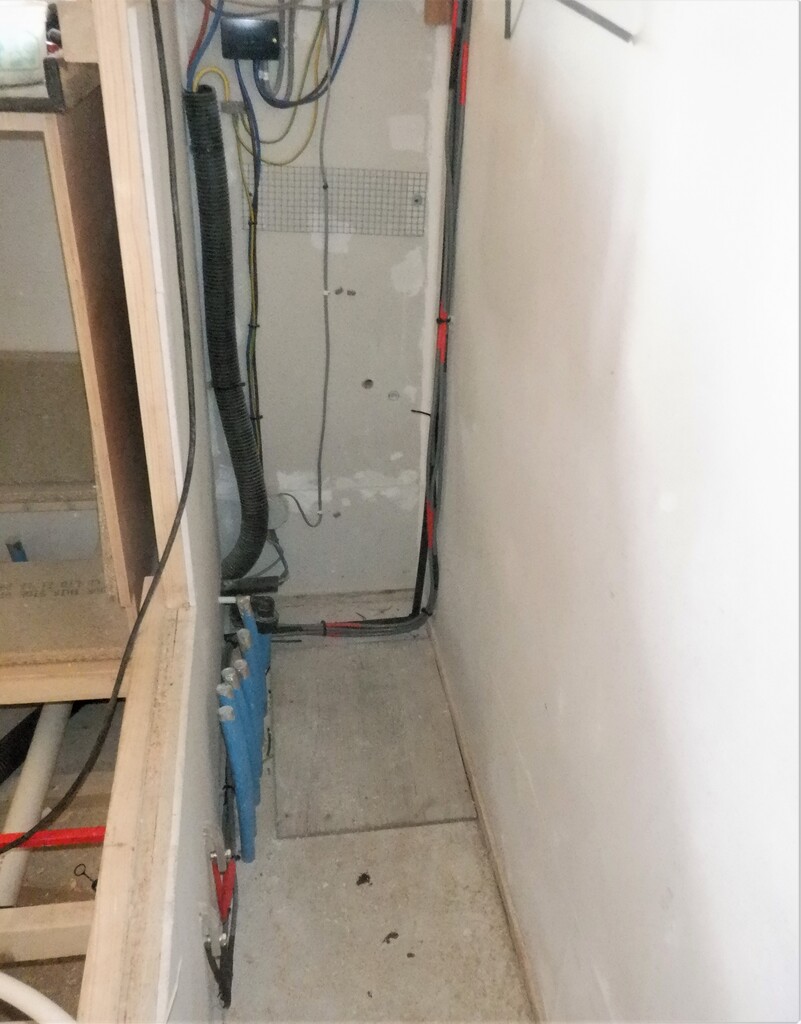
    Next, we carried the cabinet into the Tech Cupboard for a test fit and then measured the spacings on the right and left side of the cabinet and the wall. We ripped sawn a length of 2by1 timber to make a filling in piece, the right side being 32mm wide tapering down to 23mm at the top of the gap. The other side was much thinner, only 10mm at the bottom and about 7mm at the top. We also screwed a couple of fixing battens at the top of the cabinet, at the rear, to provide an anchorage mechanism to secure the whole cabinet against the wall and prevent it tipping over when one of the battery drawers, containing 100kg of weight, is opened.

    Then, we screwed on the two bus bars onto the wall behind the cabinet, to get that ready.

    Construction of Battery Cabinet

    Internal-Bus-bars-1

    Construction of Battery Cabinet

    Internal-Bus-bars-2


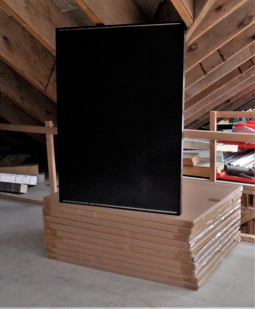
    We painted it plain black, all the drawer front panels and the front facing edges of the cabinet itself too. We didn’t bother in doing anywhere else as it will be all hidden.

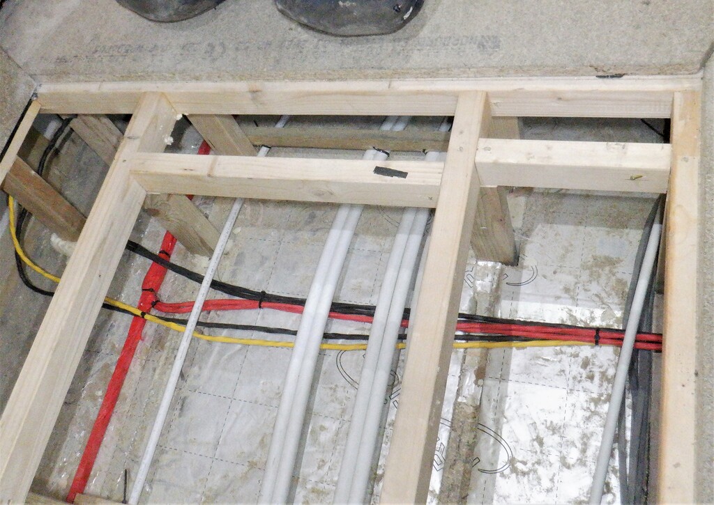
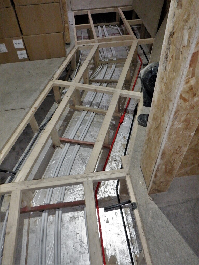
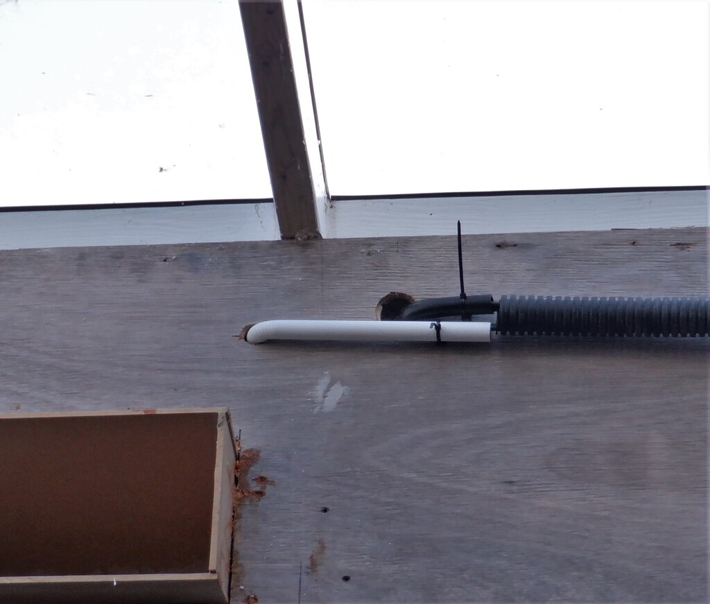
    Next, we drilled a series of extra conduit holes into the top of the right side of the cabinet to allow input and output of more cables and wires, some going upstairs to serve the rooms up there, but also, a smaller conduit going down to allow a data cable to be routed to and from the solar inverter box we have running in the Utility Cupboard, plus also this small conduit can have a 12Volt power cable threaded through to provide power for the network hubs and switches that we will have. Finally, we cut several holes into the floorboards to allow the 50mm air duct to be routed from underneath the flooring, that will be eventually connected to the main air duct out in our hallway.

    We were then ready at last, to install the cabinet into place, permanently. It got screwed tight to the wall, then some extra screws on both left and right sides and finally, a couple downwards into the floorboards, along the front rail. We inserted a 20mm conduit into the cabinet and down into the floor and connected a right angle adapter to the 50mm air pipe underneath the flooring too.

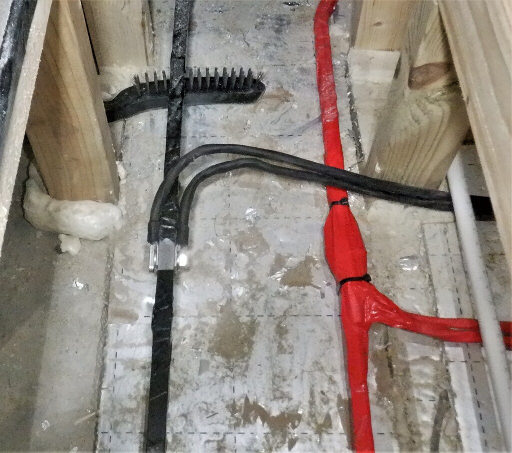
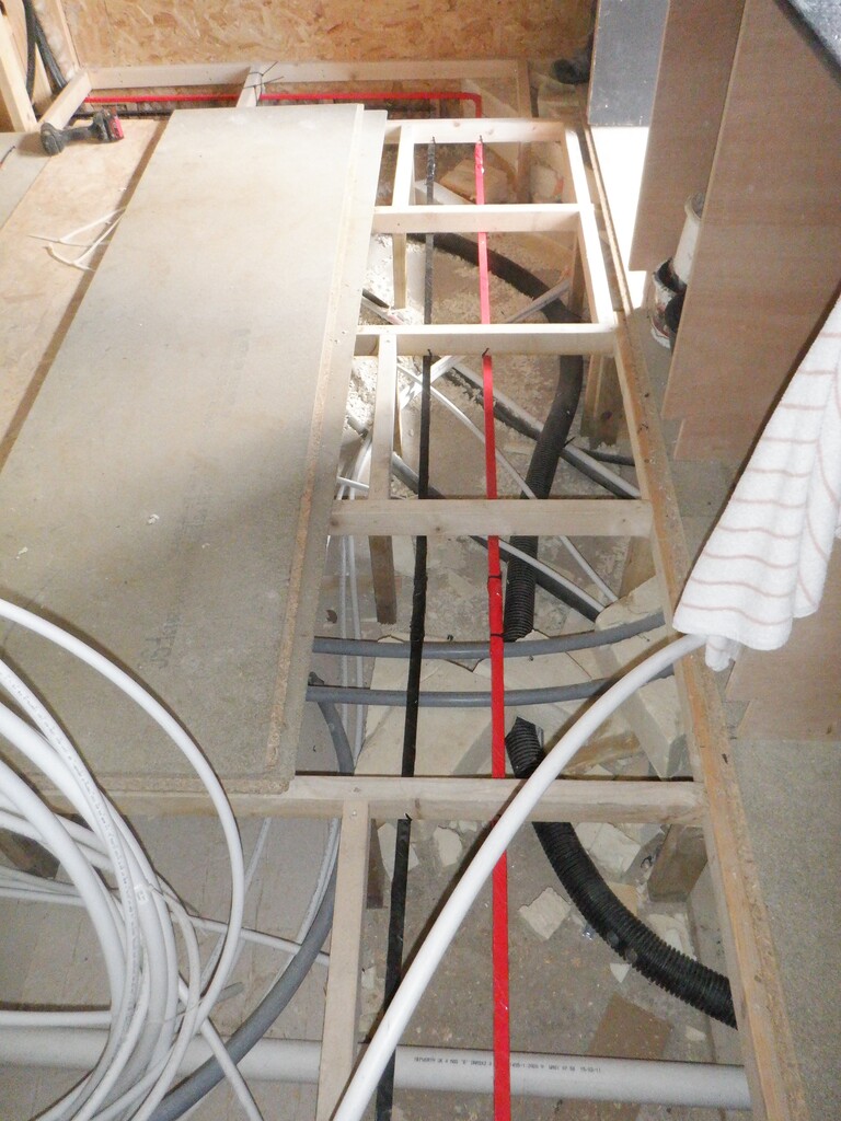
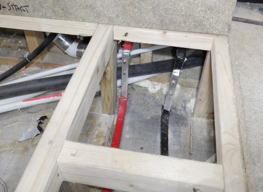
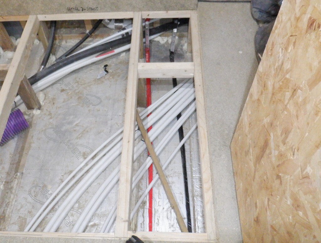
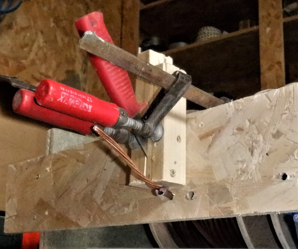
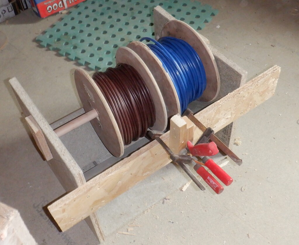
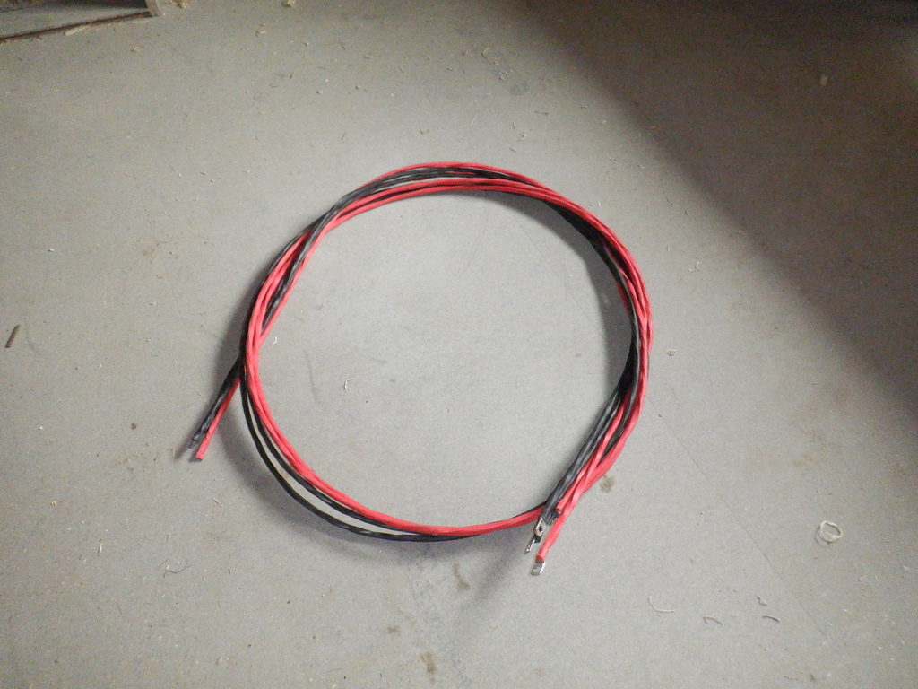
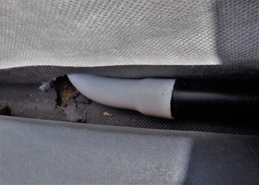
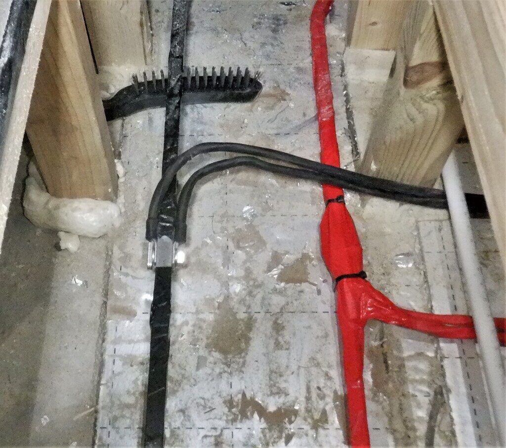
    The next job was to run some heavy duty electrical cables from the cabinet, down underneath the flooring and out to the hall and connect to our aluminium bus bars that we installed a couple of weeks ago. These cables we had made ourselves by stripping off the insulation off sixteen square millimetres (16mm²) copper cables, unwound the strands and joined two of them back together again to make a single thirty-two square millimetres (32mm2) single core which we slid on a replacement coloured heat shrink tubing. We made two of these for each half of the circuit, making a total of sixty-four square millimetres (64mm2) copper wires, capable to handle well over 200Amps of power without overheating or stressing the cables. We bolted the ends to the bus bar out in the hall and the other ends inside our battery cabinet, to our distribution terminal blocks up on the fifth layer. We also did a similar thing for our 12Volts line but only using a single home-made 32mm2 cable because we are only expecting and supplying a maximum of 100Amps.

    Construction of Battery Cabinet

    Connected-to-the-bus-bars

    Construction of Battery Cabinet

    From-bus-bar-across-the-hall

    Construction of Battery Cabinet

    Up-the-wall-to

    Construction of Battery Cabinet

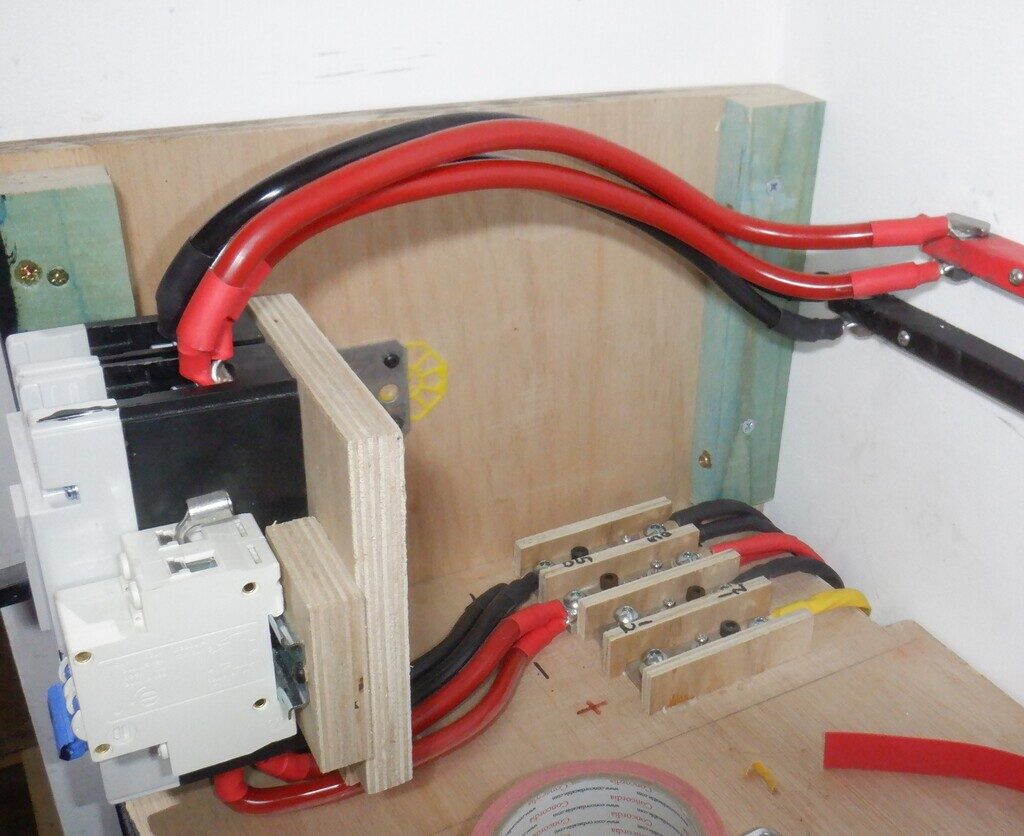
    Main-breaker-connected-from-internal-bus-bars-to-the-main-bus-bars


    We also threaded in a couple of heavy duty mains 230V wires from our Consumer Unit, across under the floor and up at the back of the cabinet, ready to be distributed inside to our five mains powered chargers plus providing a electrical socket for any other pieces of equipment going up that side of the Tech Cupboard.

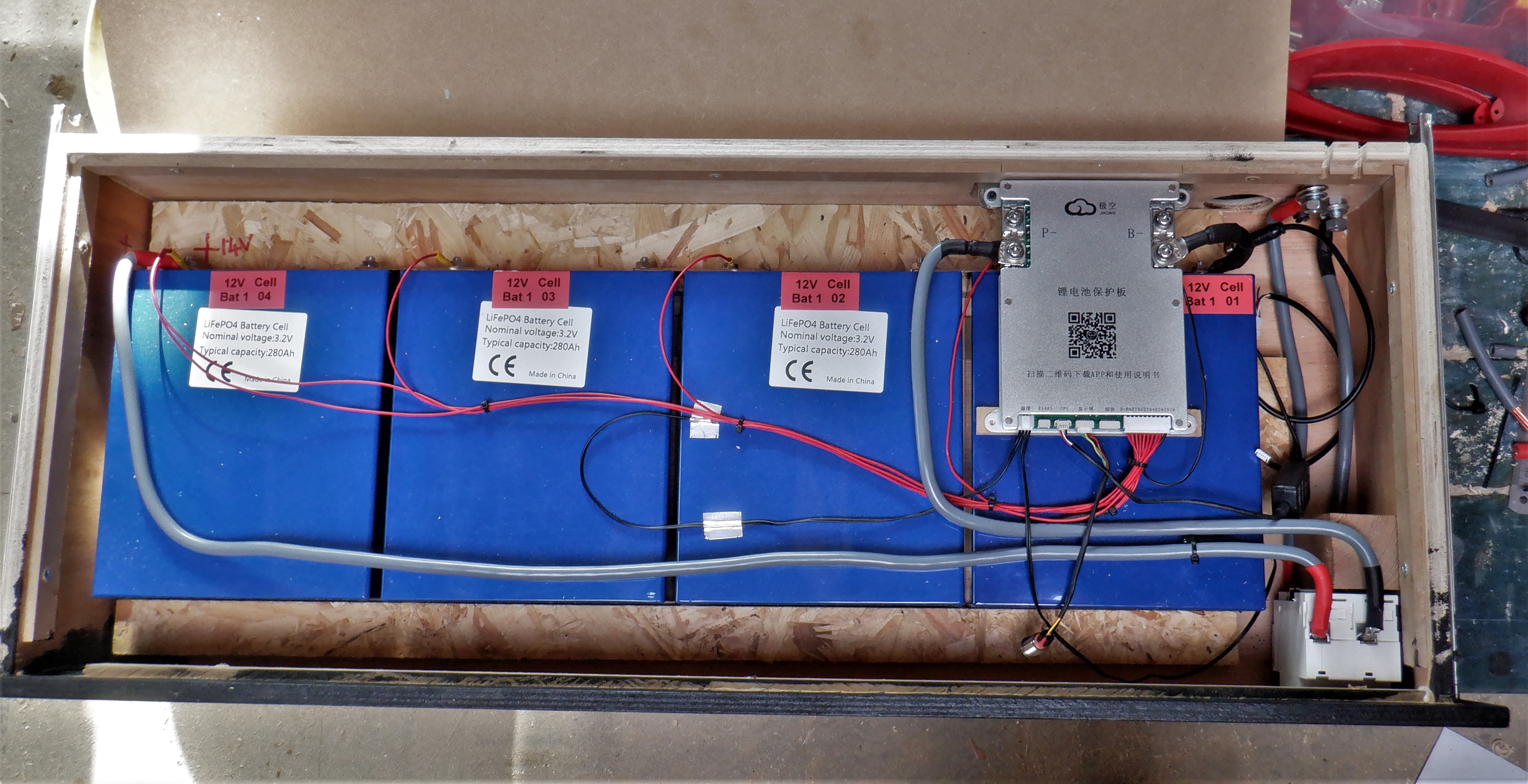
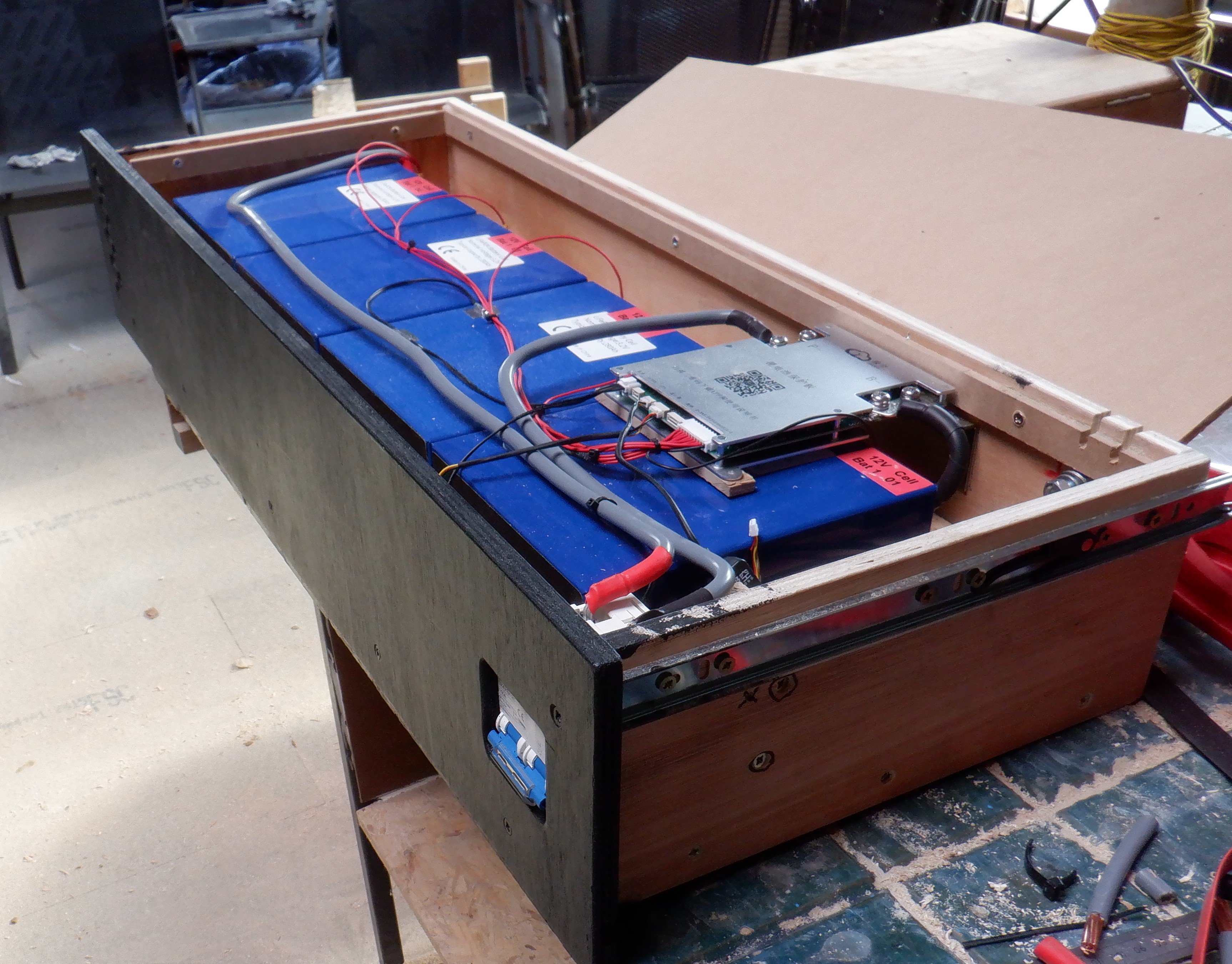
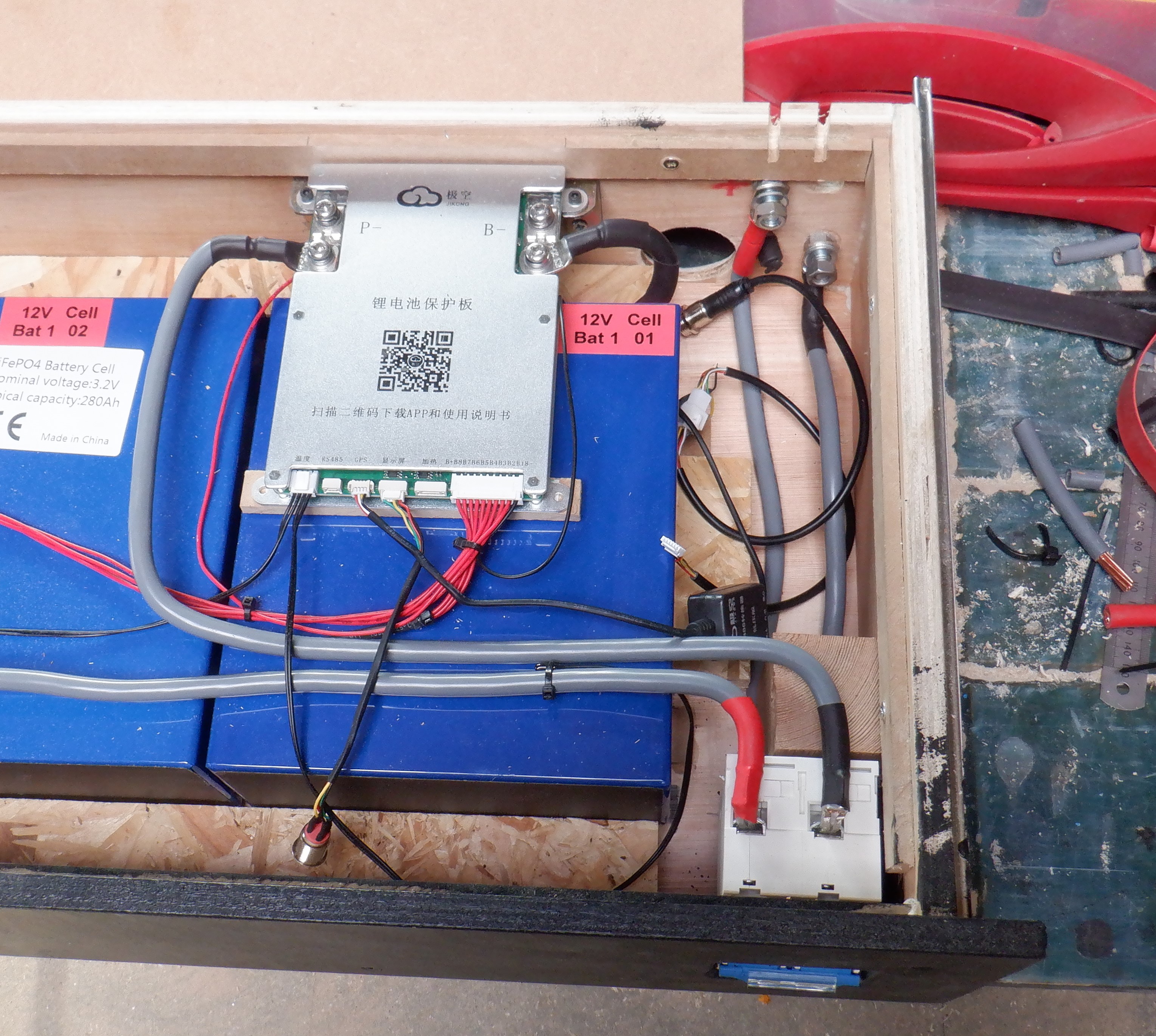
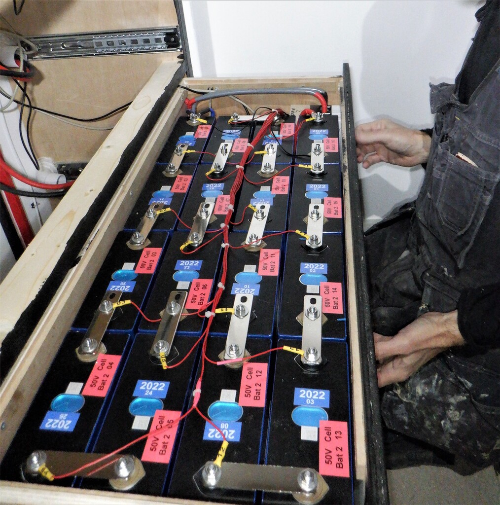
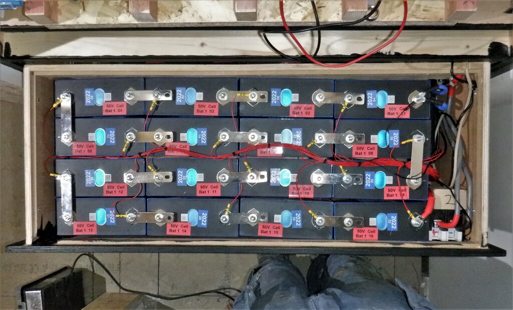
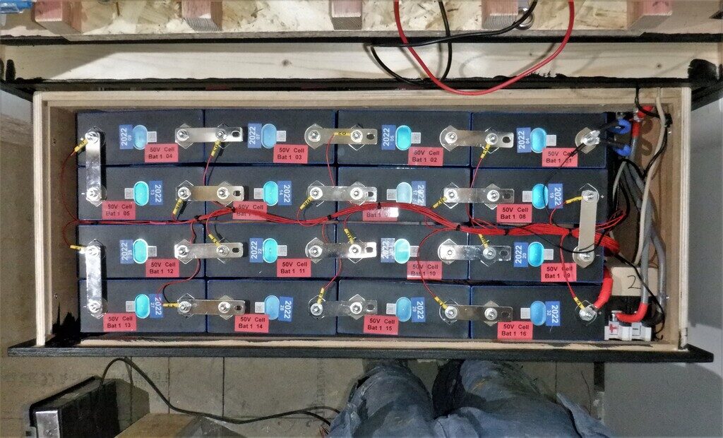
    Having done all the tasks that needed us to have access to install these various wires and cables, we could proceed to assemble an actual battery pack into a drawer. This meant that we needed to make up lots of thick heavy duty connecting electrical cables, ready to go into a drawer from the bus bar, connecting the switches, the computer and several data cables too. It took all day just to do one drawer! The sixteen individual cells all needed to be arranged so that we maximised getting them into the space inside the drawer, but have both the negative and positive terminals both at the right side of the drawer, ready to be connected to the computer and the isolating switch. We had to drill an extra hole into the solid copper bars so that we could pack the battery cells closer together. Also, the computer has monitoring wires attached to each of the sixteen cells so it can both measure what is going on, on each individual cell level, but also, transfer small amount of energy from one cell to another, to balance everything up. It is a very clever battery computer!

    Construction of Battery Cabinet

    Battery-50-2

    We repeated the whole thing over again to assemble our second battery 50Volt pack and got that one going as well.

    Construction of Battery Cabinet

    Battery-50-1

    We did all the proper safety checks, electrical tests before we switched on these drawers full of batteries. All is working just fine! Both battery packs are working and connects to the wider world of our house etc.

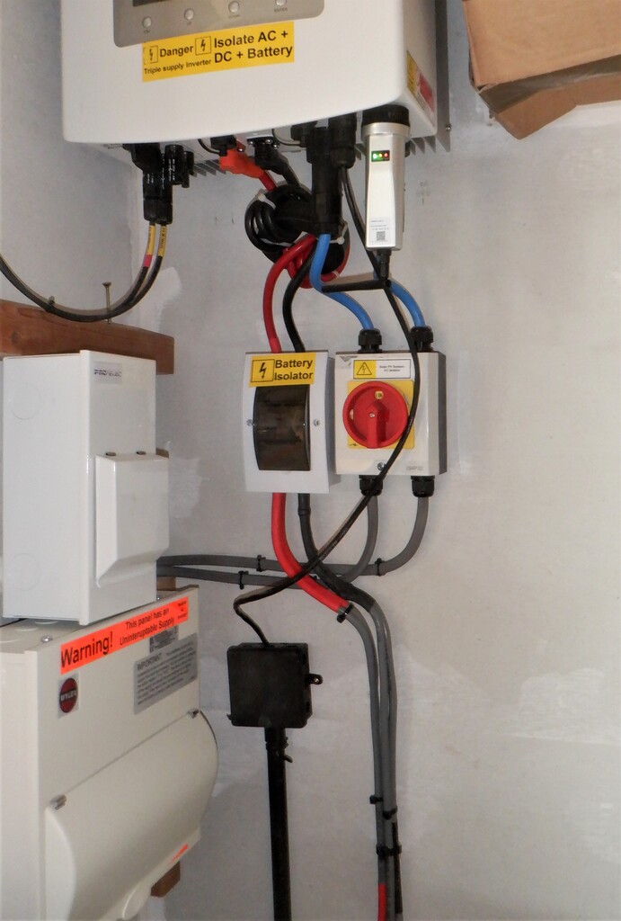
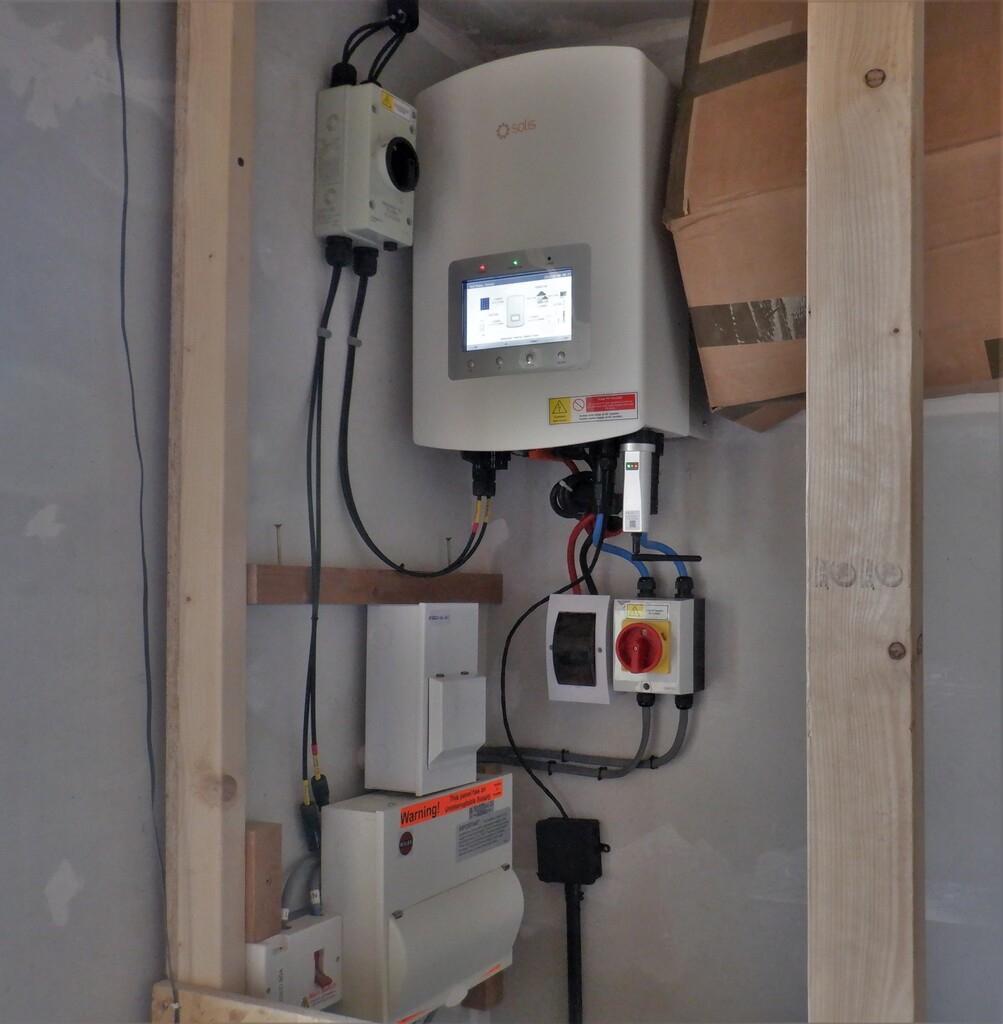
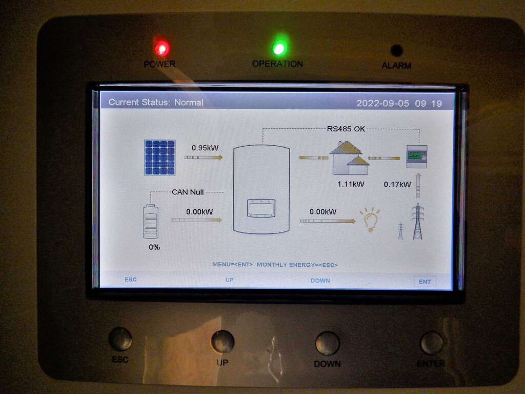
    This pretty much means that we got our battery cabinet finished, with only the 12Volt drawer to assemble and also to put the chargers into the fifth shelf which we will do later. The final test was to enable the Solar Panel system to deliver any excess solar energy and route it to the battery packs. But, unfortunately, our Inverter magic box doesn’t seems to want to do that. We thought we had configured it to reroute any excess Solar energy to charge the batteries but it kept wanting to use grid electricity instead.  We eventually realised that we had enabled the battery on the inverter with the battery switched off which made the inverter think the battery was flat and need emergency charging! We solved this by turning the battery on first then enabling it in the inverter and all was well, lovely solar energy charging the battery…

  • The Final String of Solar Panels and Equipment Ordered and Delivered

    We have been hunting around for a suitable Solar Panels to fit up inside our Skylight for the last couple of months and finally have discovered a particular source that is fairly close to the required size of 1200mm by 1030mm. Of course, when we had designed our Skylight ten years ago, we had the bright idea of building our own solar panels by buying the actual silicon wafers themselves and assembling them into a flat grid to capture the sunshine etc. because the price of the factory built panels were very high in those days. But in ten years, the price has fallen off the cliff like a large rock and it no longer made any practical sense to make our own ones when we could buy a fully working panel for peanuts! But because of economies of scale these smaller 200W panels cost more than the more popular 400W large panels!

    The Final String of Solar Panels and Equipment Ordered and Delivered

    New-panels-for-skylight


    These panels are the closest we could find to fit our windows but there is a narrow strip where it doesn’t quite cover the transparent part of the window. We will just fill in the gaps with insulation foam board pieces.
    We have ordered eleven panels for our eleven windows, each generating around the nominal 200Watts so that means another 2200Watts of energy, to add to our solar system.
    The Final String of Solar Panels and Equipment Ordered and Delivered

    Fit-panels-into-these-gaps

    The Final String of Solar Panels and Equipment Ordered and Delivered

    Down-this-side-of-the-skylight


    To convert the Solar energy into suitable voltages for charging our battery packs, we bought two solar chargers, to produce either 12Volts or 50Volts. We can select which battery we would like to charge depending on whether it needs topping up or not.
    The Final String of Solar Panels and Equipment Ordered and Delivered

    Solar-charge-controllers


    We will connect the panels into 2 strings of 4 panels and 1 string of 3 panels.
    This concludes the purchasing of all our Solar Panels and equipment, completing our investment into going Green and trying to reduce our dependency on the incredibly high electricity prices.

  • Fermacell and Plasterboards Arrives

    Yesterday and today, both at 9am, saw the delivery of another major supply of building material, this time, the finishing wall and ceiling surfaces for our house. The fermacell is a high quality sheet material, made of gypsum mixed with recycled newspapers. The paper is shredded into tiny strands and mixed with the gypsum and compressed into a very flat 10mm uniformly think board, measuring 2400mm by 1200mm. We ordered 430 sheets which we calculate should cover all our walls and ceilings for all the ground floor and first floor rooms. We also ordered 96 sheets of the more traditional plasterboards, because it is less than half the price of fermacell and we are wanting to use the plasterboard sheets to make a heavy sound-absorbing layer in the construction of the first floor flooring. We will lay two sheets on top of rubber underlay or perhaps thin glass wool that will get compressed down by the weight. The main benefit is to isolate the flooring surface from the ceiling joists so much of the contact and airborne sounds will not penetrate down into the ground floor space.
    The first morning saw the arrival of five pallets, all carried individually down the Loke on a neat little diesel powered fork-lift truck that came with the delivery lorry.

    Fermacell and Plasterboards Arrives

    Moffett-Forklift-in-action-delivering-Fermacell

    Then, we put one of our brand new tarpaulin sheets (we bought them ten years ago!), measuring 9metres by 14metres and folded it in half so we had 9metres by 7metres. This covered our first two stacks just nicely and we put on two wooden sheets over the top to protect the plastic tarpaulin from being clawed by wood pigeon and neighbour’s cats or even our resident fox. Everything was then strapped down to secure it against the wind.

    Fermacell and Plasterboards Arrives

    First-days-delivery-all-wrapped-up


    The second morning was a manic rush because the wonderful driver (Not!) arrived at the crack of dawn at 8am and we weren’t even dressed and one was in the toilet! O Boy!
    He came with our final four pallets of more Fermacell boards, each pallet having 60 sheets on board and the whole pallet weighing 2.1 tons ! To make it even more manic, we were having heavy rain showers frequently so we quickly dashed to get our second tarpaulin up and covering the second pile. We found two more 11mm OSB boards to weigh it down and protect the plastic, like before. We left it like that for a couple of days until it mostly stopped raining and we could go back to finally strap down the stack and it can survive long term.
    Fermacell and Plasterboards Arrives

    Second-delivery-of-fermacell


    Anyway, we have all the building material on hand now, to pretty much finish all the interior surfaces, on both the ground and first floor, which we hope to have done some time next year. We have avoided having to pay any future price increases, and amazingly, the fermacell sheets were at a very reasonable price of about £16 per sheet now, compared with £13 when we bought loads for the Garage ten years ago. Not bad!!

  • Forty Pallets of Foam Insulation Rejects is Delivered

    We started at 8am today to get everything ready for the arrival of forty pallets of insulation foam boards that have been rejected by various factory or reclaimed from various building projects like a hospital having two more floors fitted so the old roof was ripped off and it had 200mm thick polystyrene foam boards. The lorry with its trailer arrived at 9am and parked up on the main road at the top of our Loke. The pallets were jammed on and needed our mini-digger with our fork-lift tongs fitted to the arm and hauled off each pallet. But, the pallets were too uneven and were not securely wrapped into a tight bundles, they only used cling-film material and only went horizontally around the layers of foam bits and pieces and didn’t wrap up and over to make sure they were secured into a square block. They measured approximately 4 feet square and about 4 feet tall and they were stacked two high on the lorry. But, some of the pallets had moved and shifted around during the journey, making them difficult to unload. We even had several pallets that has fallen sideways off in the extra trailer module so we had to reassemble a number of pallets and strapped them up with our own fabric fasteners.
    We had our wonderful middle neighbours coming out to help us, helping to load two pallets on our large flatbed trolley and transporting them down the Loke and dumping them all over our garden, driveway and at the bottom of the Loke as well, while Stephen unloaded every pallet off the lorry and putting them a little way down the Loke. It was 12:30pm before we had finished that first stage of this massive task. The Loke was well and truly covered in pallets!

    Forty Pallets of Foam Insulation Rejects is Delivered

    Loke-blokced-with-insulation


    After lunch, we continued in moving two pallets at a time on our trolley and stacking the pallets around outside our house, in corners and all along the side of the Garage.
    Forty Pallets of Foam Insulation Rejects is Delivered

    Its-quite-a-long-trek


    The Loke eventually became clear and open for vehicles again at around 4pm. We tidied up some of the bits and pieces, put back our mini-digger and restored our fencing again, and call it a day at around 5pm. It was a long day!!
    Then on the following day, we then moved the remaining fourteen pallets off the bottom of the Loke, with the marvellous assistance of our immediate neighbour, to break apart the pallets and move the individual pieces of foam boards and stacked them on top of our first row of pallets alongside the Garage and around the corner at the back of the house.
    Forty Pallets of Foam Insulation Rejects is Delivered

    Insulation-all-pliled-up-1

    Forty Pallets of Foam Insulation Rejects is Delivered

    Insulation-all-pliled-up-2

    Forty Pallets of Foam Insulation Rejects is Delivered

    Insulation-all-pliled-up-3

    Forty Pallets of Foam Insulation Rejects is Delivered

    Insulation-all-pliled-up-4


    We tied down the great big long bundle of boards with a rope and also placed heavy concrete blocks on top, to make sure none will blow away if the wind gets up.
    The last five pallets that were dumped in front of our house, were moved around to the alcove section at the back of the house, but only after we had dismantled the wooden platforms we had there from when we were doing the Solar Panels and moved mum’s plants.

    It is now all tidied up and the Loke and front of the house is looking good again. We now finally have our source of foam boards to go up inside our roof rafters to complete the building shell of of super thick insulation. We will resume that particular task when we have finished construction and commissioning our battery storage and installed solar panels on the P Roof.

  • Installation of the 50Volts Electricity Bus Bars to Connect Solar Inverter to Our Battery Packs

    We started the process of installing a heavy duty electrical Bus Bar that will carry the power from the Solar Panels via the Inverter to our battery packs in the Tech Cupboard. The inverter can handle up to 5kW, in either converting the solar energy into battery voltages (which is 50Volts) or is taking the battery power and converting it into mains 230Volts electricity. This means that the 50Volts bus bars will have to carry up to 100Amps to maximise the 5kWatts capabilities of the Inverter box. But, this 100Amps is only half the story, we are going to be wanting to distribute this source of power all over the house, to power the various pieces of equipment, like for example, all the lighting in all the rooms and also air duct heaters just to name one or two things. With this in mind, we need to have a ceiling of around 200Amps to make sure we can handle the peak loads at certain times of the day. We probably will never see that kind of power requirements, but, just in case.
    With this in mind, 200Amps means that we need to have electric wiring that is about sixty-four square millimetres (64mm2) of copper wires in open air. Just for comparison, the usual domestic wiring for putting a ring mains around a room uses a 2.5mm2,to give about 20Amps. But, copper wires are very expensive and we need at least 25metres for the main part running from the Tech Cupboard and in both directions down the halls. So, we bought, several years ago, Aluminium solid metal bars measuring 19mm by 12mm (228 mm²). Aluminium is a pretty good conductor of electricity (although the alloy in the bars is not as good), so it’s not very far behind Copper in world terms.

    So we mapped out where we wanted the 50Volts bus bars to go down the hall, entering the Utility Room, avoiding the other pipes and conduits already there, turning the corner and heading for the Plant Cupboard at the other side of the room. It needed quite a few bends and we had already a heavy duty metal bar bender that we screwed down on to our work table in the Garage. We did have to heat up the Aluminium bars with a gas torch to help with the effort of bending in the 19mm direction. We also had our big table top vice mounted here on the table so we can give some of the bars a 90 degree twist, in order to get the direction going in the correct orientation.

    Installation of the 50Volts Electricity Bus Bars to Connect Solar Inverter to Our Battery Packs

    Multi-bend-bus-bars-from-utility-to-hall

    Each section are then joined together by overlapping about 100mm of the two bars, rubbing the contact surfaces clean of oxidation and quickly applied a thin layer of zinc impregnated grease and clamped together using two nuts and bolts to squeeze the joint very tight indeed, forcing the grease to be expelled and leaving behind the zinc metal filings to ensure a good electrical low-resistance connection. The grease will also stop the join from oxidising over the years.

    Installation of the 50Volts Electricity Bus Bars to Connect Solar Inverter to Our Battery Packs

    Busbar-joint-

    We now have a pair of aluminium bars running all the way from the Plant Cupboard in the Utility Room, across the room, into the hall and nearly all the way to the Kitchen, going pass the Tech Cupboard. They have been wrapped up in coloured duct tape to protect against accidental electric shorts.

    Installation of the 50Volts Electricity Bus Bars to Connect Solar Inverter to Our Battery Packs

    Bus-bars-entering-the-plant-cupboard

    Then, we took a pair of twenty-five square millimetre (25mm2) cables and crimped mounting tags on the ends, and connected this pair to one of the aluminium bars coming into the Plant Cupboard, putting on red heat shrink tubing to colour code it. We did the same again but for the other aluminium bar, the negative side, colour coded as black. All four cables were then sent along inside the cupboard and then across and finally, up the wall to terminate in the cut-off switch that is located just underneath the Inverter box.

    Installation of the 50Volts Electricity Bus Bars to Connect Solar Inverter to Our Battery Packs

    Changing-to-dual-25mm²-cables-to-connect-to-the-inverter

    Installation of the 50Volts Electricity Bus Bars to Connect Solar Inverter to Our Battery Packs

    Through-a-isolation-switch


    Installation of the 50Volts Electricity Bus Bars to Connect Solar Inverter to Our Battery Packs

    Acrross-utility-room

    Installation of the 50Volts Electricity Bus Bars to Connect Solar Inverter to Our Battery Packs

    Down-to-the-bottom

    Installation of the 50Volts Electricity Bus Bars to Connect Solar Inverter to Our Battery Packs

    Allong-the-hall

    Installation of the 50Volts Electricity Bus Bars to Connect Solar Inverter to Our Battery Packs

    Past-the-Tech-cupboard


    Next, we repeated a similar task, but this time, for the Tech Cupboard, and this time, we used four sixteen square millimetre (16mm2) wires, but this time, we stripped off the original insulation, joined two of them back together by spreading apart the individual strands and remerging them back together to form a single thirty-two square millimetre (32mm2) copper wire, recovered in a single piece of more coloured heat shrink tubing. We made two of these so the total capacity is sixty-four square millimetre (64mm2) which will be plenty to carry at least 200Amps. Again, we repeated this process and produced another twin wires set but in black for the negative side. These heavy duty cables were then bolted onto the aluminium bars out in the hall, just outside the Tech Cupboard and then threaded through drilled holes in the floorboards inside the cupboard, right flushed against the left side wall where we are going to have our battery cabinet.

    Installation of the 50Volts Electricity Bus Bars to Connect Solar Inverter to Our Battery Packs

    Knife-slits-the-insulation

    Installation of the 50Volts Electricity Bus Bars to Connect Solar Inverter to Our Battery Packs

    whilst-the-cable-in-unrolled

    Installation of the 50Volts Electricity Bus Bars to Connect Solar Inverter to Our Battery Packs

    Made-up-32mm²-copper-cables


    That concludes the main bus bars and connections to the two cupboards, next we will be designing and building the battery cabinet with four drawers and one shelf to store the battery cells, computers, display modules and charger modules.

  • Finished Lining Tech Cupboard with Fermacell

    We started the new week with a job of finishing lining the Tech Cupboard with our Fermacell boards. We wanted to get this little room all done so that we could start installing the batteries and the heavy-duty electric bus bars that will route the power from our batteries that will be located in this Tech Cupboard and get this 50Volts DC power running up and down our hallways, but most especially, to our Utility Room and over to the Plant Cupboard where we got our Solar Inverter box so we can charge our batteries using the power of the Sun.

    The metal leg (one of seven that holds up the Skylight and roof!) was completely encapsulated with a layer of 18mm OSB board and then covered in the 10mm thick fermacell material. The walls are also covered in 18mm OSB boards plus the fermacell, so we can now screw shelving brackets anywhere in our Tech Cupboard

    Finished Lining Tech Cupboard with Fermacell

    Tech-cupboard-lined-and-filled

    We then filled in all the little staple holes and also rounded all the corners with Polyfilla, rubbed it all down and then gave the whole room a good thick coat of white paint.

    Finished Lining Tech Cupboard with Fermacell

    Tech-cupboard-Painted-1

    Finished Lining Tech Cupboard with Fermacell

    Tech-cupboard-Painted-2


    That is that done and we can now start creating battery storage cabinets, equipment shelves and installing high powered electricity bus bars and network patch panels etc.

  • Delivery of Lithium Iron Phosphate Cells

    We had the delivery of our long-awaited lithium iron phosphate (LiFePO) cells, arriving in two separate assignments, 5 boxes yesterday and the 4 boxes today.

    Delivery of Lithium Iron Phosphate Cells

    nine-boxes-of-cells


    We now got thirty-six large cells, ready to be combined into three separate battery packs, two of them being 50Volts and the third 12Volts. The 50Volts packs are both approximately 15kWh capacity and the 12Volts is just under 4kWh.
    Delivery of Lithium Iron Phosphate Cells

    A-290Ah-LiFePO-cell

    Delivery of Lithium Iron Phosphate Cells

    each-box-holds-4-cells


    Each cell measures 174mm tall, 220mm wide and 72mm thick, weighs about 6kg, so we will need strong and sturdy shelves to hold 16 of them (96kg!) in our Tech Cupboard.

  • Stage One of Mounting of Solar Panels on Roof

    We started the new week with a new complete change of project, with the installation of our new Solar Panels on our slate roof. We have seventeen panels to mount, ten on the M roof (overlooking the Swimming lane, slightly West of South) and seven out on the P roof (overlooking our Patio, pointing slightly East of South), using a collection of metal brackets and horizontal aluminium rails.
    But, we have to make this job as easy and safe first, so we pulled out four old scaffold platforms we had stored and re-assembled them. We put two in the alcove formed by the L, M and N segments of the house, and anchoring then to the walls by hooking a thin piece of plywood behind the window wings and joining the two module together too. We put up safety boards along the edge of the platforms to provide tactile warnings of the looming edges and then tied a ladder up against one of the shorter edges.
    We did the same around the corner in the Patio area so we can gain access to the P roof section too.

    One of the jobs we did prior to this point, was to paint about a third of the metal brackets with a primer and black paint, to match the black colour of the Solar Panels but also our dark slate tiles too. We didn’t want to have silvery gleam poking out around the edges of the panels.

    So, we then proceeded to install these chunky metal brackets, using the black painted ones where they would be seen, and the unpainted ones in the middle. We needed eight rows of brackets, grouped into four sets, as we have four rows of panels  on this M roof segment. The first row from the bottom is a single panel and it has four brackets. We twisted the slate hook sideways to release the slate and then able to slide it downwards with a strong wiggle and tugs. We calculated that the first position for the brackets would be eight rows of tiles from the bottom of the roof, aligned up on the main roof rafter underneath. We removed half dozen tiles to exposed the vertical batten and then we could screw the metal bracket using 100mm heavy duty coach screws, two of them for each bracket down on the batten and screws deeps into the main structural rafter underneath.

    Remove-Slates-to-expose-rafter-and-fix-hook

    Remove-Slates-to-expose-rafter-and-fix-hook

    Stage One of Mounting of Solar Panels on Roof

    Notch-slate-below-hook-and-refix


    Then we put a plastic flashing protector over the bracket and cut each slate to fit around the “nose” that is sticking up above the surface of the slate tiles. Usually we needed to trim three slates and sometimes we had to remove the original hook nail and had to nail the newly shaped tile in with old fashioned copper nails instead. It was quite a task to wiggle the slates back into place, sometimes needing to remove more, just so others could go back in again.
    Stage One of Mounting of Solar Panels on Roof

    Place-flashing-over-hook

    Stage One of Mounting of Solar Panels on Roof

    Notch-slate-around-flashing-and-replace


    It was a fairly slow process and we had thirty-six of them to do for this roof and it took us three days to complete this task.
    The placement of the brackets were mapped out so that the set of ten panels were positioned as far leftwards as possible, to avoid the potential shadow created by the ridge line on the right side of the roof.
    Stage One of Mounting of Solar Panels on Roof

    M-First-2-brackets

    Stage One of Mounting of Solar Panels on Roof

    M-First-5-rows-of-brackets

    Stage One of Mounting of Solar Panels on Roof

    M-All-8-Rows-of-Brackets


    We were interrupted with this job by rain on Thursday and other commitments on Friday, so we worked indoors installing a 40mm flexible conduit to take the four solar panel cables, all the way from the Skylight near the Great Room, right along to the other end, routed down inside one of the rafters to the external wall position and then along the floorboard into the corner that is over the Utility Room downstairs, where we drilled a hole through the ceiling panel and the lid to the Equipment Cupboard and stop just inside. We can now thread the the four separate double insulated 4mm copper wires all the way from the control box to the panels outside on the roof. The last job, which we haven’t done yet, is to drill a hole or two through the kerb wall itself, up in the Skylight to provide that final access for the wires to get out onto the roof.

    Then we installed the hybrid inverter on the wall inside our Equipment Cupboard, tucked in the corner just right of the window. There is (will be) a door above the worktop and we would be able to pull it open to read the status display on the front of this box of electronics magic!
    There is a lot of safety switches and fuses that had to be installed around this Invertor, to make sure that we can at any time, disconnect any part of the system, like for example, the batteries, or the solar panels or indeed the mains electricity as well.

    Inverter-and-connections

    Inverter-and-connections

    Back on the roof, we then proceeded to drill two 20mm holes through the kerb of the Skylight, one for a conduit to go straight out on the M roof and slide under the tile battens and down to the first metal bracket. The second hole had a 20mm conduit turning a sharp right angle turn and running along the kerb behind the flashing rubber membrane and aluminium strip, to end up out on the P roof, curving around to a metal bracket ready connecting to the top solar panels out there. We bent the other ends of the two conduits so it went flat along the kerb inside the Skylight and went to where the 40mm flexible conduit ended.
    The next job was to thread the four cables through the conduit we had previously put in, but, we discovered a very annoying difficulty. There were too many bends and the conduit was too flexible as well, and our cable kept jamming after we had only pulled through ten metres or so. We even tried using a motorised winch to provide 250Kg pulling power but we broke the rope and cable connection and it went ping!!
    So, in the end, we had to cut up our lovely conduit and threaded the four cables in sections. We finally made it and got the wires going down into the Utility Room, ready to be connected to the cut-off switch and the other ends going right up in the Skylight and going through the two 20mm conduits we put up earlier. We pulled through enough cable for both roof sections and make sure one half of the twin cables was long enough to reach the bottom of the roof too.

    Stage One of Mounting of Solar Panels on Roof

    Conduit-through-the-kerb-before-sealing

    Stage One of Mounting of Solar Panels on Roof

    Conduit-inside-the-skylight

    Stage One of Mounting of Solar Panels on Roof

    solar-cable-run-along-the-skylight

    Stage One of Mounting of Solar Panels on Roof

    Through-the-skylight-frame-and-around


    Stage One of Mounting of Solar Panels on Roof

    the-corner-and-through-the-ends-of-the-rafters-until

    Stage One of Mounting of Solar Panels on Roof

    it-comes-down-a-rafter-and-along-the-bottom-to-the-Utility-room-in-the-corner


    The next job was to create the aluminium horizontal rails that will connect to the sticking up metal brackets and form four sets of support bars that will hold the solar panels in place. They then needed their ends painted black to disguise the shiny silvery gleam, just like what we already have done to the metal brackets.

    Stage One of Mounting of Solar Panels on Roof

    Ends-af-rails-painted

    Now that we have the wires in place, and also connected to our isolation switch back in the Utility Room, we proceeded to install the first ten of our Solar Panels, starting at the top with four panels in a line. Two aluminium support bars were joined together and then anchored to the seven metal brackets for each rail. We then carefully carried up each Solar Panel module up one by one, connecting the cable into each panel, making sure that we had every panel pointing in the same orientation, with the positive connection point upwards.

    Stage One of Mounting of Solar Panels on Roof

    First-panel-in-place


    We slowly proceeded for each new line of panels, three panels in the second row, and then just two for the next line and finally finishing off with the single panel at the bottom.
    Stage One of Mounting of Solar Panels on Roof

    Solar-on-M-finished


    To make sure that the wires were working, and that each lie of panels were ok, we connected the negative wire to the last panel in the line and measured the voltage back in the Utility Room. The first row produced 156Volts. We repeated this test every time we had completed a line and we were getting higher and higher measurements each time which is very good news.
    The final measurement returned 392Volts for all ten panels.

    The last thing we did for this stage of work, was to connect the output of these Solar Panels to our Inverter magic box and switch it on. It came alive and showing that we had a connection to our Solar Panels and it immediately started reporting that we were generating 2kW of electricity. This was in the evening at 6pm so that wasn’t too bad at all.

    Stage One of Mounting of Solar Panels on Roof

    Inverter-display


    One of the things the Inverter wanted, was a electricity current sensor fitted to our household mains connection going into the smart meter so it can calculate how much we are drawing from the mains and adjust its own circuits to avoid exporting any excess electricity out on to the National Grid. This is good because we won’t get paid for any exported energy and strictly speaking, we are not allowed anyway.
    So we had to install a bunch of network cables from the House to the Garage, we took the opportunity to also include a replacement LAN network cable that will go all the way back to the Tech Cupboard plus also a telephone landline extension so that we can have our DECT base station in the house instead of the garage. The third cable is the connection for the mains current sensor but that one needed to be threaded up to our Utility Channel in the garage and then all the way along to the front of the building where it terminated in a network socket. We had to unscrew every other section covering the Utility Channel, screw a series of L hooks to keep our data cable away from all the mains electricity that is already crowding the bottom half of the channel and tie little cable ties to keep it all nice and neat.

    I conclude this report now but to finish off with some further numbers, during Saturday, yesterday, while we were working on sorting out the network cables, the Solar Panels collected another 16kWh (kilo watt hour) or 16 units of electricity, we had the Inverter box switched on from about 9am and looking at the historical data, for this time of the year, it matches what we had generated. Very Nice!

  • Intruder Alert!

    Today, we discovered that we had an intruder sometime in the last 24 hours. We found a reel of wire flung across our Great Room and badly chewed. It was our double insulated 4mm cable for our Solar Panels which is very annoying.

    Intruder Alert!

    Chewed-cable


    But, we also discovered that lots of our windows have been clawed and ripped as well, the plastic showing plenty of damaged. Boxes of things shredded and strewn around.
    Intruder Alert!

    Window-bottoms-clawed-to-bits-1

    Intruder Alert!

    Window-bottoms-clawed-to-bits-2

    Intruder Alert!

    Window-bottoms-clawed-to-bits-3

    Intruder Alert!

    Window-bottoms-clawed-to-bits-4


    And a bin bag full of scrap cloth and the contents scattered too.
    Intruder Alert!

    Rags-strewn-around

    It seems that we had the company of a fox, probably a youngster who was just exploring. We had taken to opening the Conservatory door wide open during the day while we worked on the roof installing the metal brackets etc. and this fox took the opportunity to sneak in and have a play. We know that it must have been either yesterday afternoon when the reel of wire was chewed because we had moved those reels of wires that very morning and of course, they were fine.

    Then, we were working upstairs and discovered more evidence, this time a patch of water right in the corner of the floor and at first, we thought that we had a leak but we didn’t have any rain for days! But, the smell gave it away, it was urine! O Boy! This was the afternoon and it was quite hot so we were surprised that it hadn’t all evaporated away by now, if the intruder was only around during the previous afternoon. But, now, perhaps we accidentally trapped the fox indoors when we locked up the place last evening and it couldn’t escape. We had a look around everywhere and even lifted up the hallway hatches to look underneath but there was no signs of it, no paw prints in the dust. No signs of it upstairs, hiding in the corner etc.

    At the end of the day we left out a bowl of water and a plate with a slice of ham on it, and put it in the middle of our Great Room and went home.

    Lo and behold the food was gone in the morning, so the intruder was still inside…

    We had another search and still could find no sign of it. We left the doors open whilst searching and saw a fox trot past a windows and thought it had left! But to be certain we put some more food down after closing the doors again.

    We came back later and the food was gone again. So we decided to leave the conservatory door ajar in the evening and we smoothed the sand outside the door to show tracks.

    We checked the sand about 9pm and saw a lovely set of tracks leaving the house! So we shut the door and sighed in relief that the poor ‘Fox’ had escaped.

    We will be closing the doors when we are not in the house in the future….