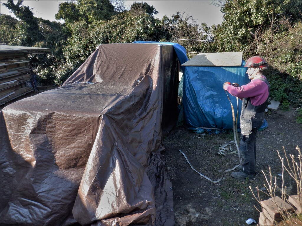
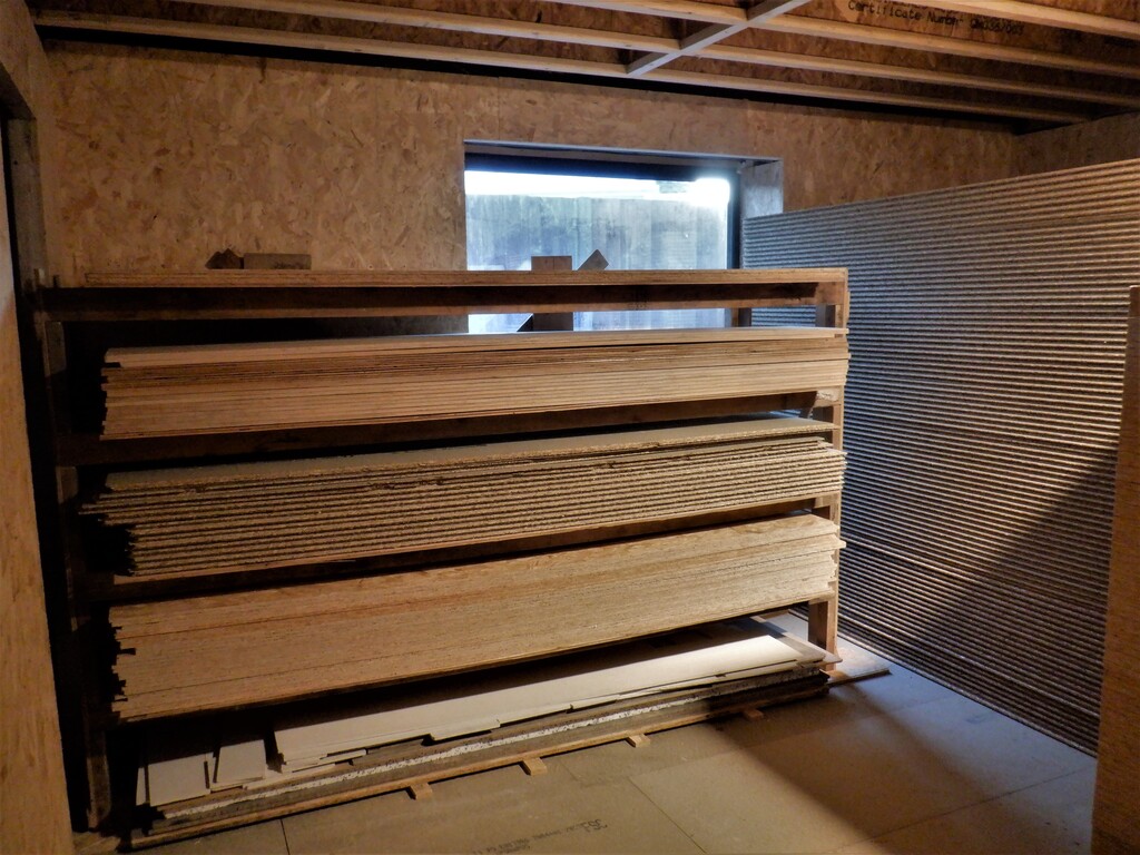
While we wait for more insulation PU foam boards to come from the scrap material merchant, we got on with the next task to do, to get the walls insulated and boarded on our various Hallways on the Ground floor. But, before we can cover up everything, we need to install all the conduits and pipes that needs to go upstairs or up to the hall ceilings.
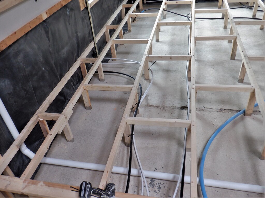
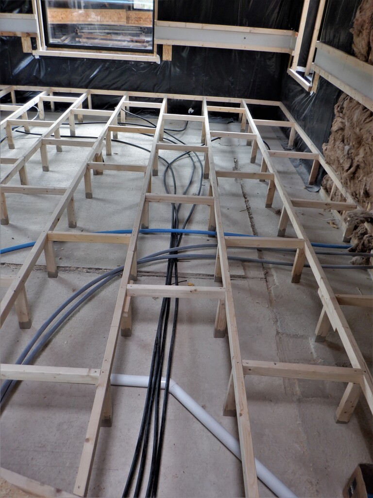
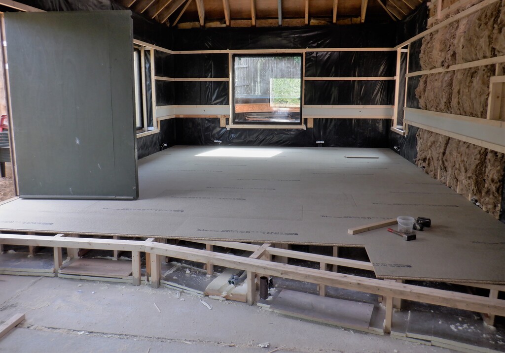
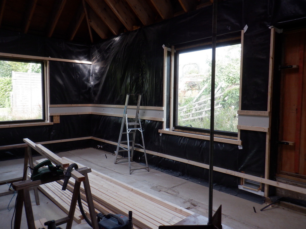
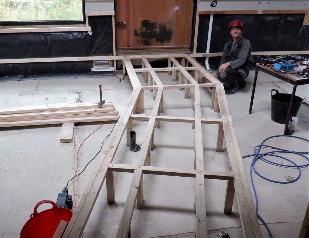
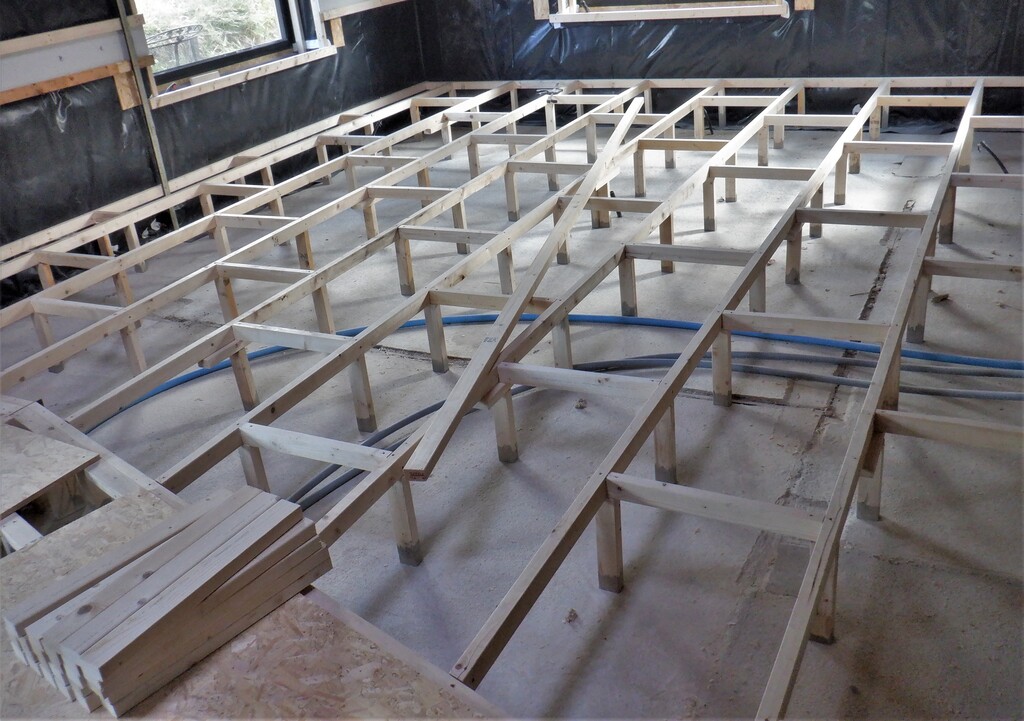
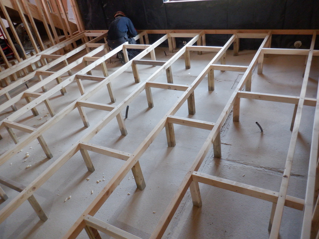
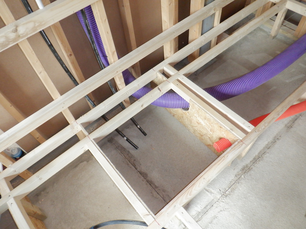
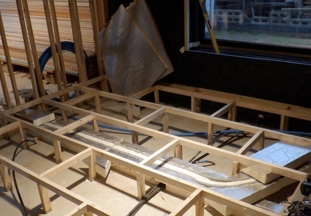
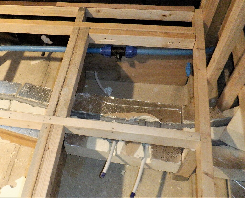
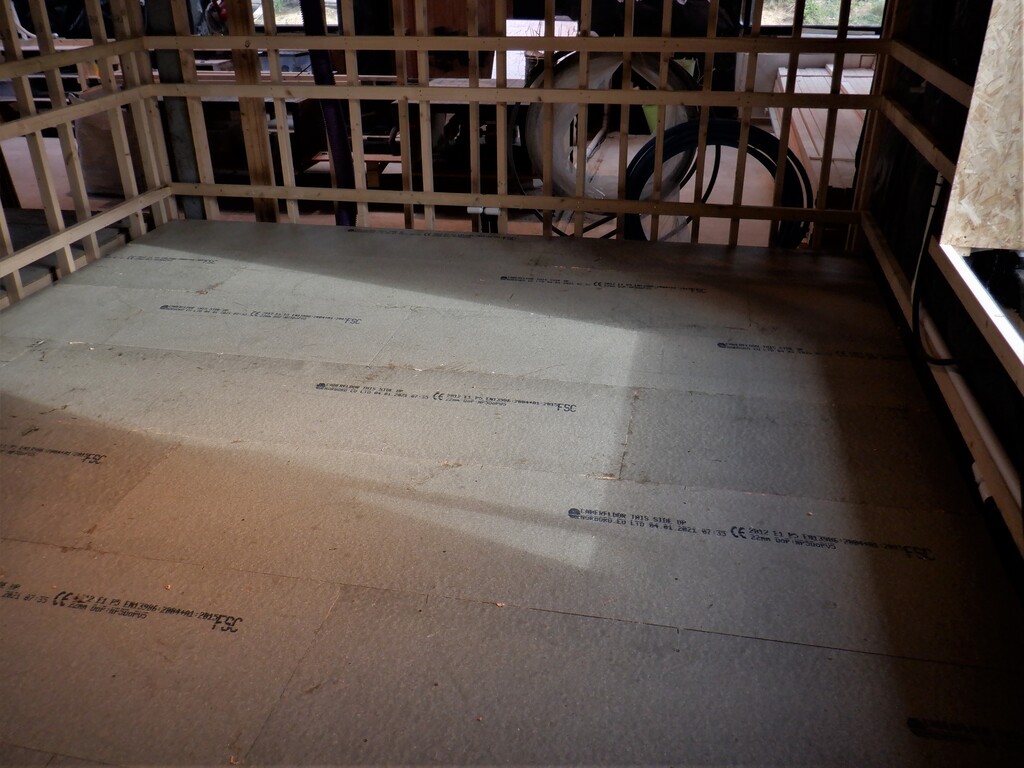
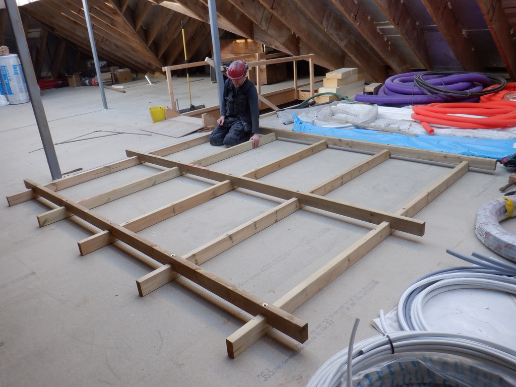
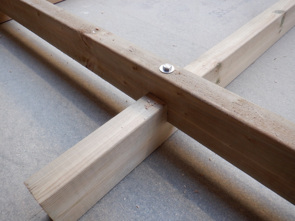
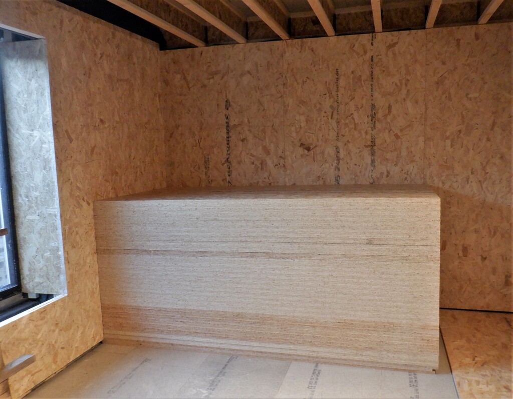
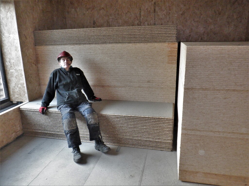
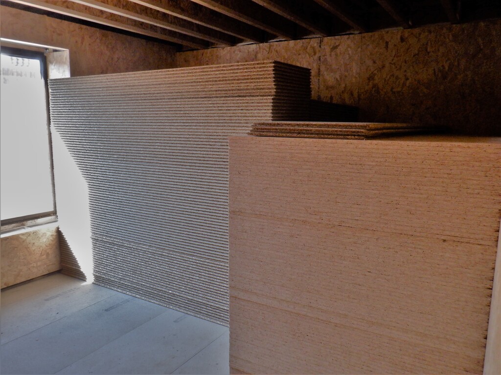
To aid in this task, we decided that the Cloakroom and Linen cupboard would have their floors built so we could route any pipes etc underneath. We did our usual procedure of using the green laser level to give us the height of the flooring, nailed the framework around and across the floor and cut to size loose 22mm chipboard floorboards.
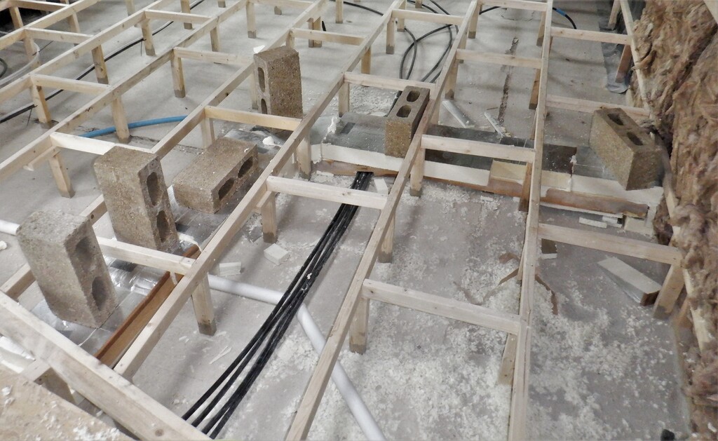
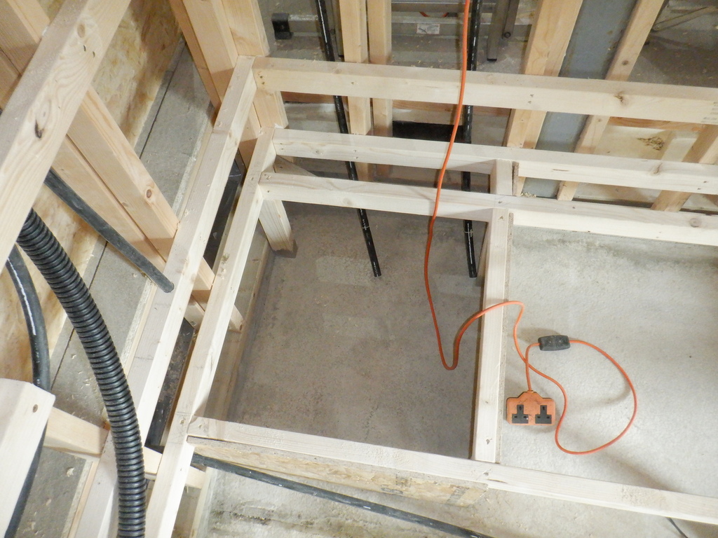
The floorboards are not glued or screwed down so we can lift them up easily for doing our routing of any Utility pipes, ducting or conduits.
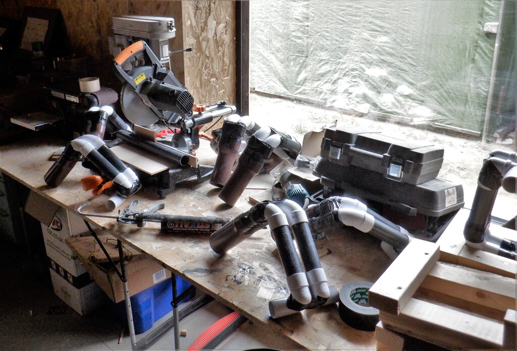
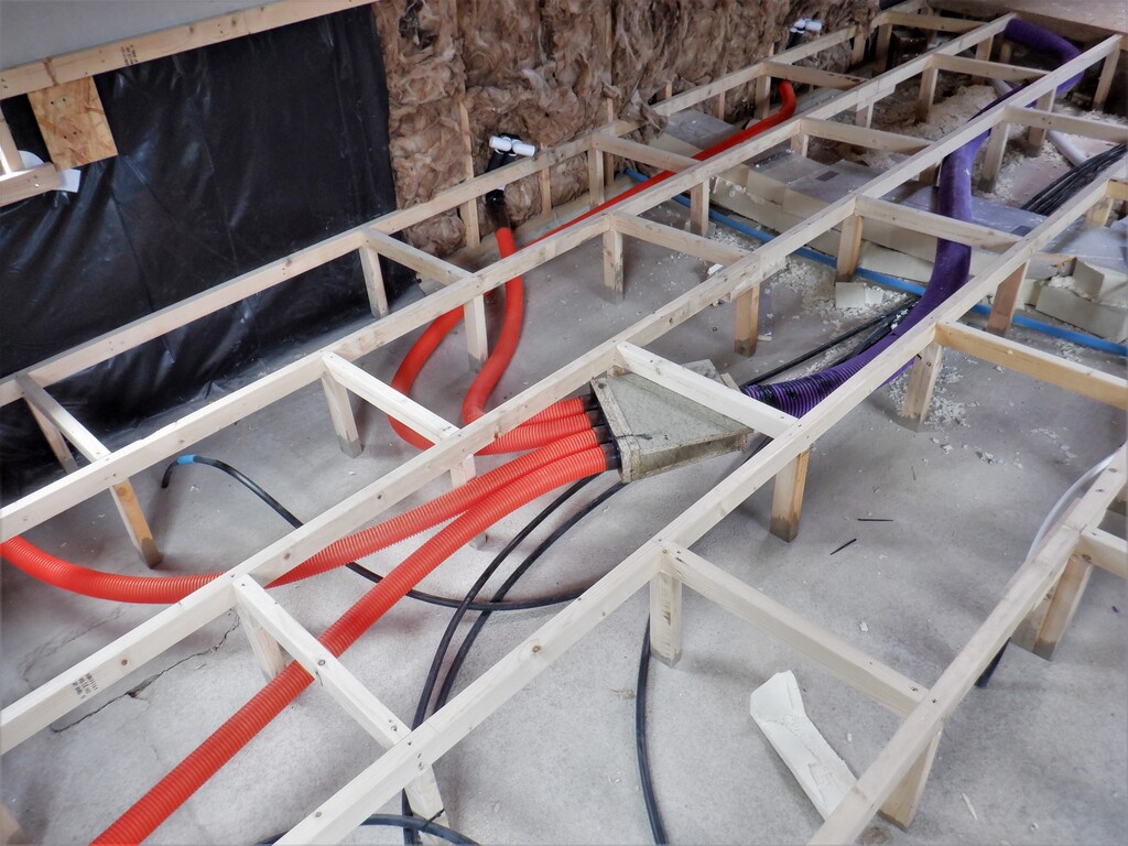
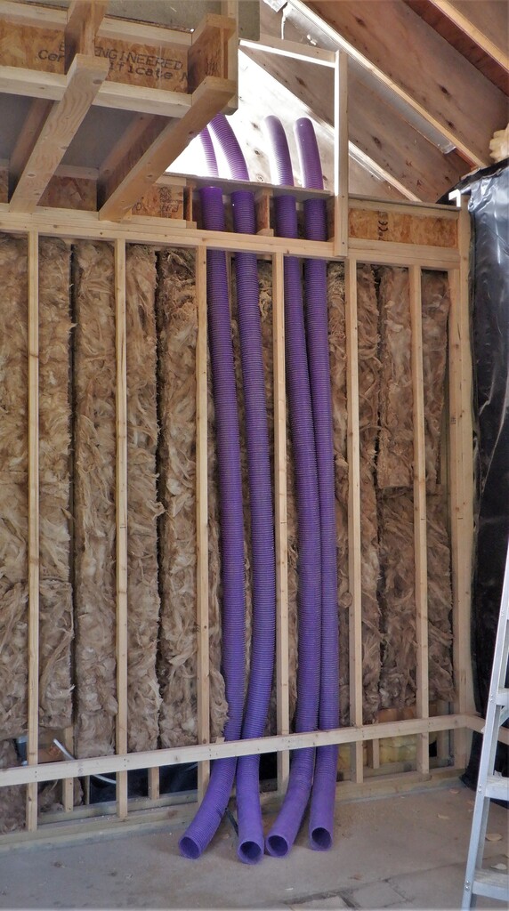
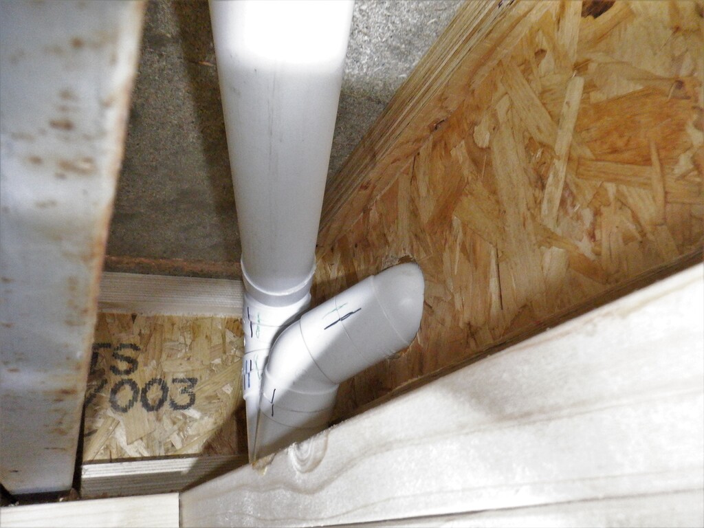
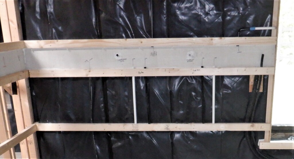
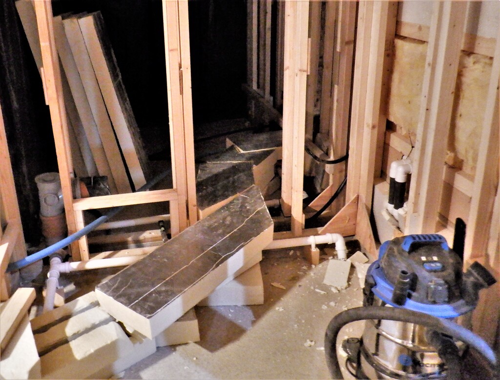
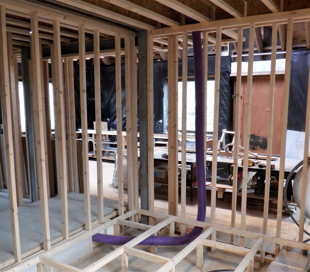
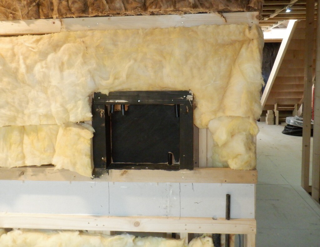
One of the first utility we did was the vacuum ducting pipework, to extend the capability of providing a vacuum cleaning service upstairs. It was going up inside the wall just right of the Cloakroom sliding door module and it needed two junctions at the top, one for the “port” for the mini hallway upstairs and a second pipe run going off to the work room to provide local vacuum facilities for plugging into various machinery. Each junction needed two 45° fittings joined together to make the right angle turn. We wanted to have more gentle turns so we avoid encountering blockages hidden inside the network somewhere. But having two 45° units fitted together, they are quite bulky so we had to wiggle, twist and trim down various joints before we had our solution.
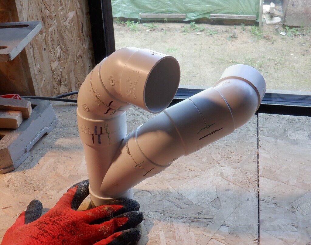
Complicated-vacuum-pipe-junction

From-the-joint
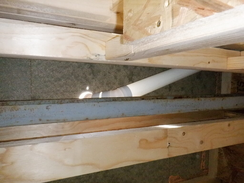
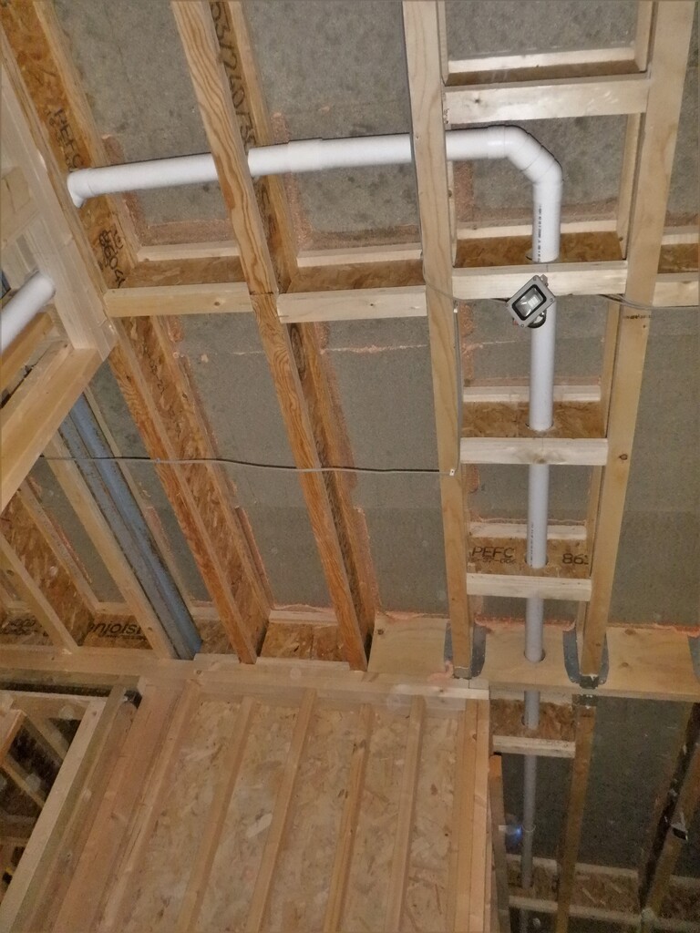
Vacuum-pipe-for-upstairs-hall
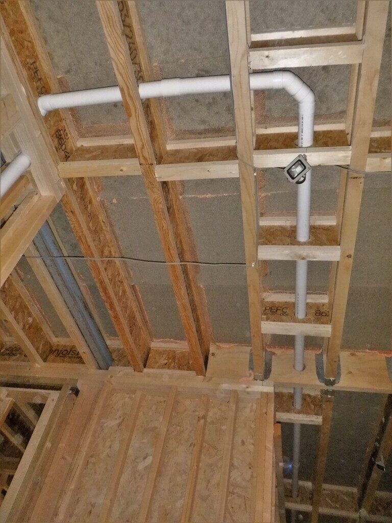
And-down-the-hall-towards-the-utility
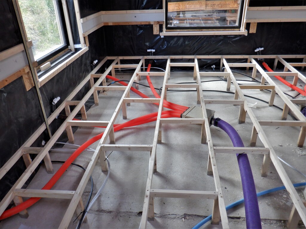
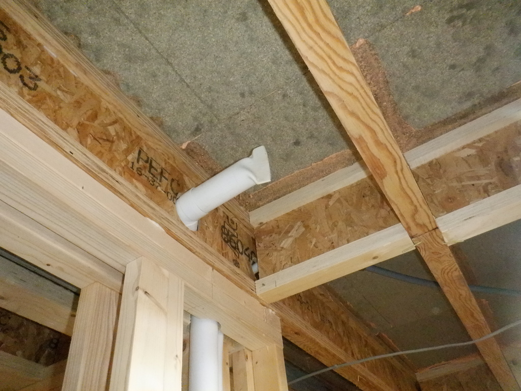
But we did realise that we had missed a shorter connection, to provide a port for upstairs in the workshop room. We already had a vacuum port downstairs next to the Utility Room, on the end wall of the hallway! So, we made some adjustments and removed a long straight section. Then we extended the new location upwards instead, making it come out upstairs that will be the workshop.
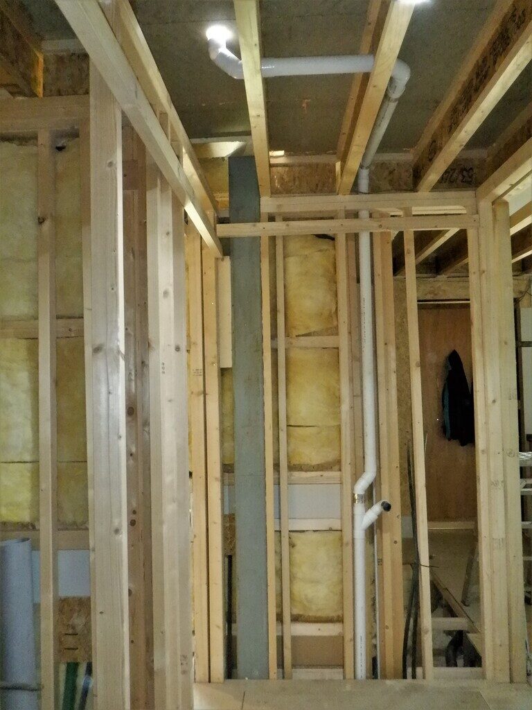
Shorter-route-to-Work-3
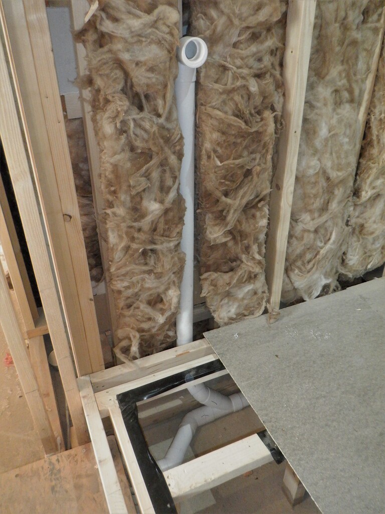
Vacuum-branch-sealed-off
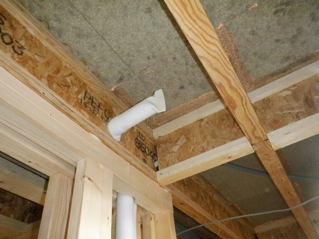
The other location for another vacuum port is all the way down next to the Great Room entrance so that we can plug in the hose and do any cleaning jobs in the Kitchen, Bedroom One, or indeed the Great room too.

Vacuum-port-for-Great-room-and-Kitchen
We also bought some adapters, to reduce the 50mm diameter down to the 40mm size because we discovered that the manufactured “pretty” vacuum port themselves can plug straight into a 40mm socket without any other items or adapters.
We now have three ports downstairs (plus another one to do across the Great Room near the Conservatory later on) and two upstairs minimum and maybe a third one for connecting to various equipment like a band saw or drill press in the workshop.
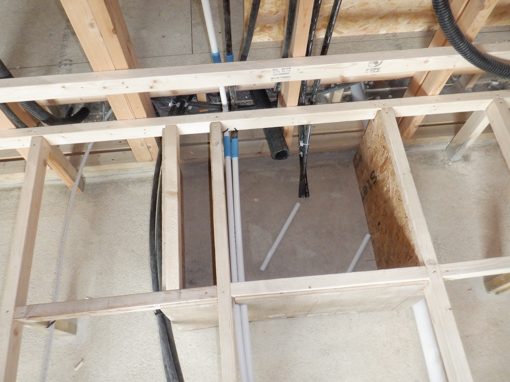
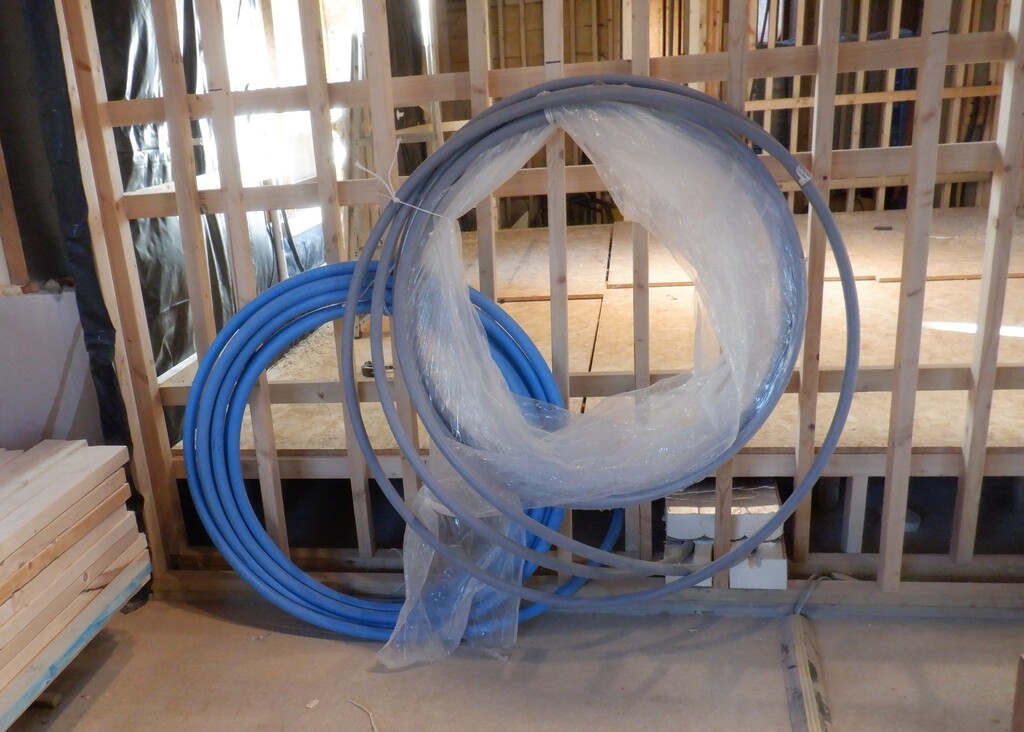
Then, the next utility to deal with, is the compressed air supply. We inserted a 22mm plumbing pipe up near the cloakroom and ran a line all the way down the hall up in the ceiling space, to give a local supply up in the workshop somewhere. All the sliding doors will have compressed air cylinders to provide a powerful and quick motive force to opening and closing the doors. We have seven sliding doors in total, not including the sliding door we got in our Garage already. So we inserted 20mm black conduit pipes at each of the sliding door modules, the Cloakroom, the Bathroom and another one for upstairs bathroom too. The ensuites already have these conduits installed. The final two, the Kitchen and Great Room also had been installed too.
We are thinking of extending the compress airline, all the way across the Great Room and put a connection in the Conservatory, alongside a Vacuum port as well.
Another set of conduit pipe was installed in various locations from the Hallway, this time it is for routing a fire suppression system up to the ceiling, to enable a nozzle to be placed in the middle of the ceiling in each large room. These nozzles will generate a water vapour “fog” to reduce the heat and severity of a potential outbreak of a fire. We have been researching on the web for the different suppression and there were several types of nozzles, some spraying droplets of water and others producing a mist or a fog. The empty conduits will allow us to thread a thin water pipe up to the ceiling so we can install such a system later on when we are satisfied with the appropriate design. The conduit is a black 25mm diameter polyethene pipe that we had purchased 10 years ago and it is big enough for us to thread water pipes up to 15mm in diameter.
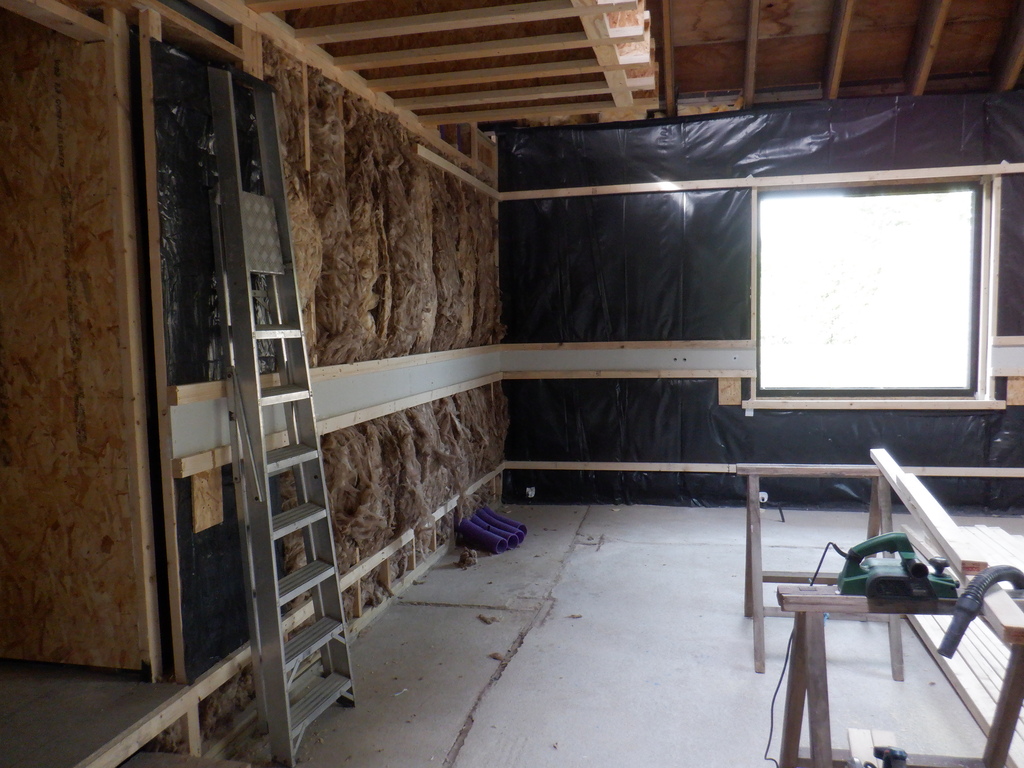
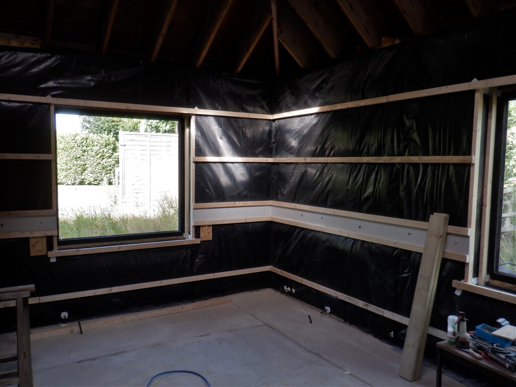
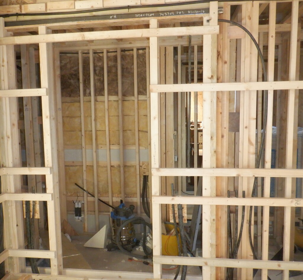
Now, after we had finished checking our list of connections for the walls and halls, we got on with nailing up the various utility horizontal rails on the walls as per standard design.
One section of wall had to be extended to form the understairs cupboard, the Kitchen wall, coming out another 1260mm and then turning and heading towards the edge of the stairs.

New-understair-cupboard-1
There is a standard 800mm door entrance, which is nicely aligned with the Cloakroom’s own entrance, which provides access to this small cupboard, going only a few feet under the stairs. The rest of the space underneath the stairs will be divided up into a set of sliding modules on wheels that will provide additional storage facilities, we can never have enough storage capacity in a modern house! The cupboard is a bit over 1300mm deep and we decided to build the back wall with short length of our Utility Channel, which will take a spur off from the Kitchen, and this will provide access to mains and other cabling, to charge up cordless equipment and the like.
New-understair-cupboard-2
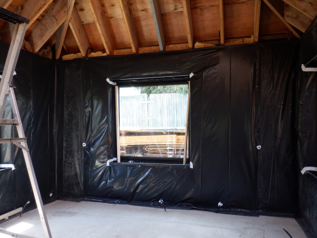
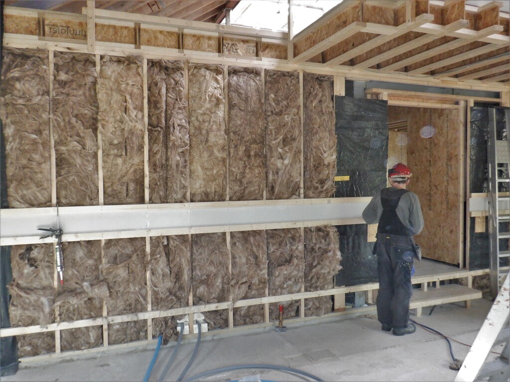
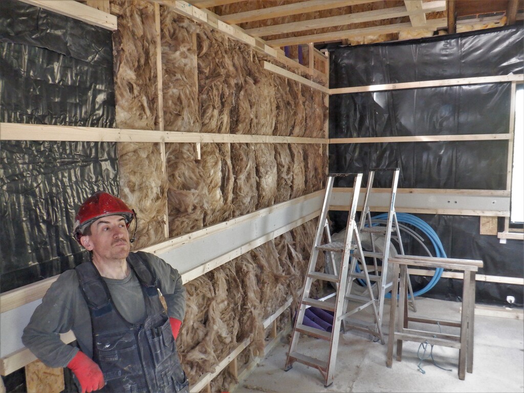
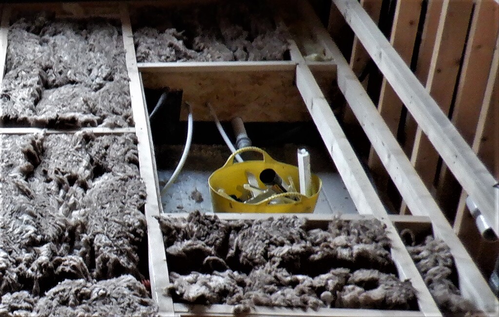
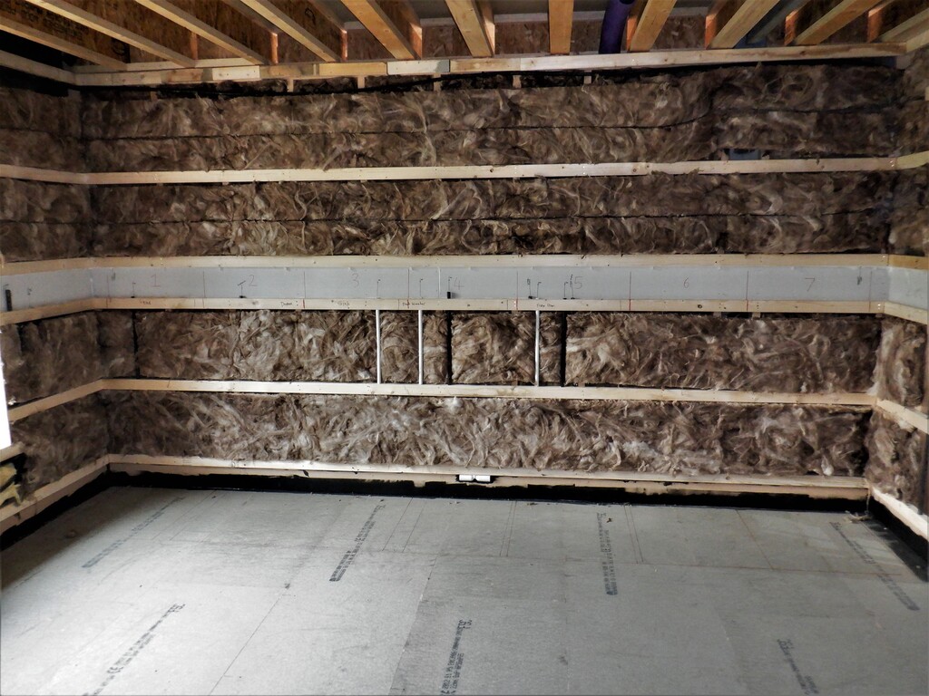
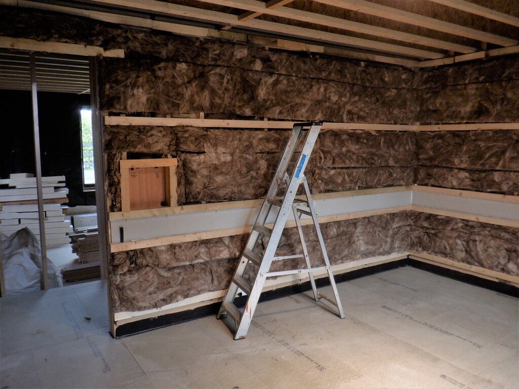
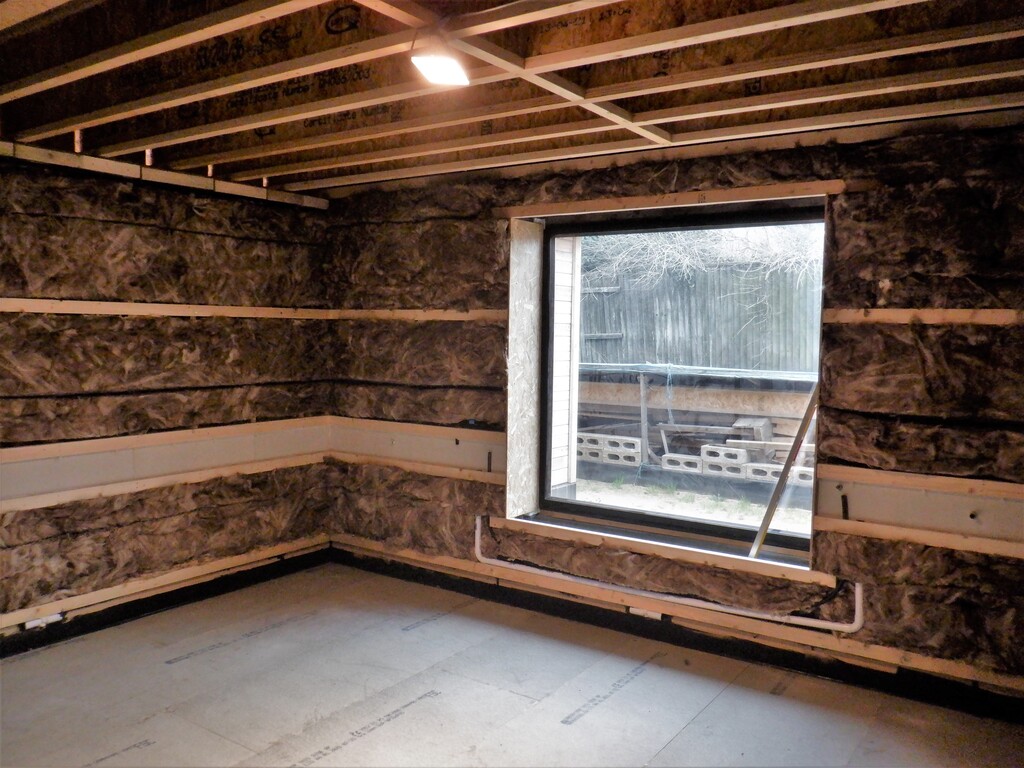
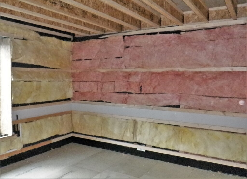
Also, as part of putting up the horizontal rails, we have been stuffing in lots of glass wool into the walls cavities to both block the sounds but also provide better fire protection. This is a very yukky job and we were wearing our dust masks with great relief, to say the least!
The Utility Channel was created as per normal, being located at the 800mm to 900mm position up the walls and we put in more conduits to make sure every section is accessible. We also built the “control box” near the Front Door to house the touch display panel but we won’t have any of the other bits and pieces inside (like fuses and audio amplifiers etc), mainly because it is not in a central location and would have meant long cable runs. So we are having a underfloor “control box” instead, located in the central part of the hall, where all the arms of the hallways meets together.
One of the other jobs we had to do, was to drill several holes through the concrete block walls of the Entertainment Room, to provide more access to the Utility Channel inside the room later on. But, because the solid nature of a concrete wall doesn’t allow us to fit the conduits and pipes in where we want with simple ease, hence why we had to drill through the concrete and insert a couple of 32mm diameter and 20mm conduits, going down into the underfloor space in the hallways next to the entrance.
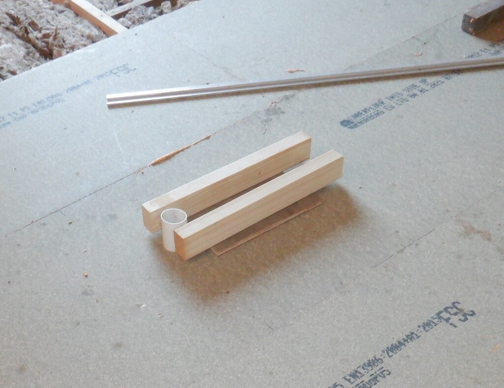
The Air Channel, running around the bottom of the walls was created. We made four more air distributor modules, using the 40mm diameter plastic plumbing pipe parts but this time, with a right angle extra piece so the air ducting won’t stick out into the crowded space under the floorboards. We located one down Hall Three (near the Utility Room), another one along Hall Two section, outside the Kitchen and the final two are down by the Front Door, to provide both fresh and warm air to the coats and hats but also to give a boost to counteract any chilly air that rushes in when the door is opened. The 150mm high MDF 6mm thick strips were stapled and glued into place on all the wall sections, including the one going down to the Great Room where we had to finish off the floorboard, the last 420mm strip to reach the entrance.
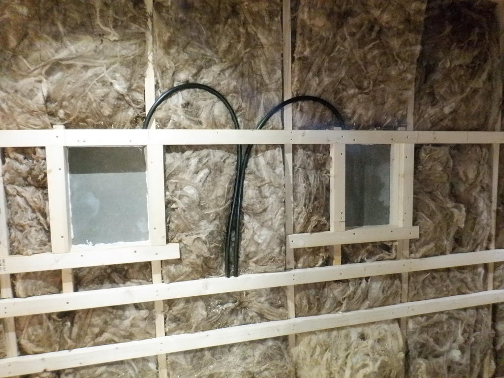
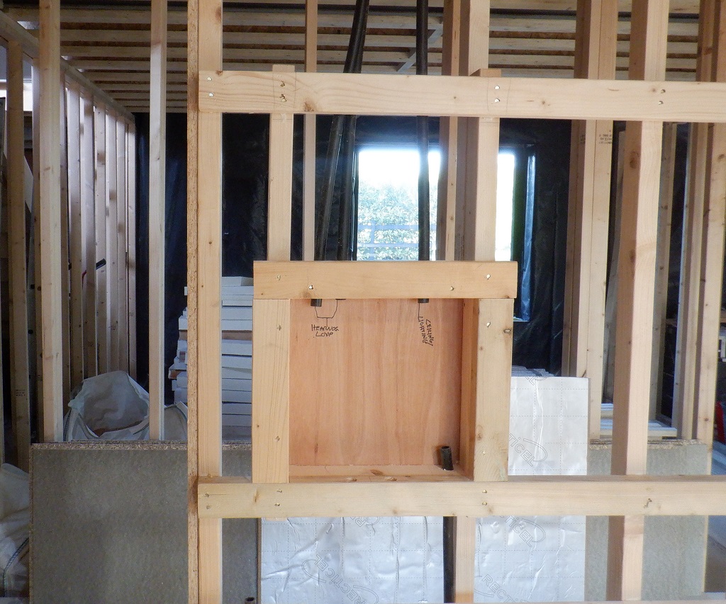
Then, we continued putting up horizontal rails at the eye line point and finally, at the top of the walls, ready to have the OSB sheets fitted. But before we can do that particular job, we wanted to break up the long sections of wall so we created five Niches on several section of our halls, two are located down Hall One towards the Great Room opposite the Kitchen, one just on Hall Two next to the Bathroom entrance, the fourth one is located half way down Hall Three towards the Utility Room and the final one is around the corner on Hall Four just before the Entertainment Room’s entrance. They are all the same at 320mm wide by 420mm high and the basic depth is 101mm (except for the last one on the Entertainment Room because the wall leg is 25mm wider so this niche is deeper).
We built up the box using pieces of CLS timber and then glued a back panel on the back for three of them, to box off from the glass wool material. So, when we have put on the wall boards and the final finishing layer, these niches will be 125mm deep and if we put a oak “sill” in the bottom and it sticks out another 25mm, then we could have these little spaces in our walls that is six inches deep, enough for a vase of flowers or other things like ornaments. We also routed a 20mm conduit around from the Utility Channel to the top corner to provide a possible connection to provide built-in lighting, to give these niches a lovely soft glow.
Hall-niches-with-conduits-to-utility-channel
And then, we inserted a few more conduits around our sliding door modules plus also a large conduit that goes up to the back wall of the Kitchen, aligned with the Utility channel where fatter and larger electric cables can be installed for the ovens and the hobs. Also, we inserted wooden lintels over various doorways, mainly the cupboards ones but also inserted small pieces of battens up inside the sliding door modules as well as a vertical post on either side of the entrance way, so it is ready to receive the pretty Oak architraves going around the edge of the door hole.
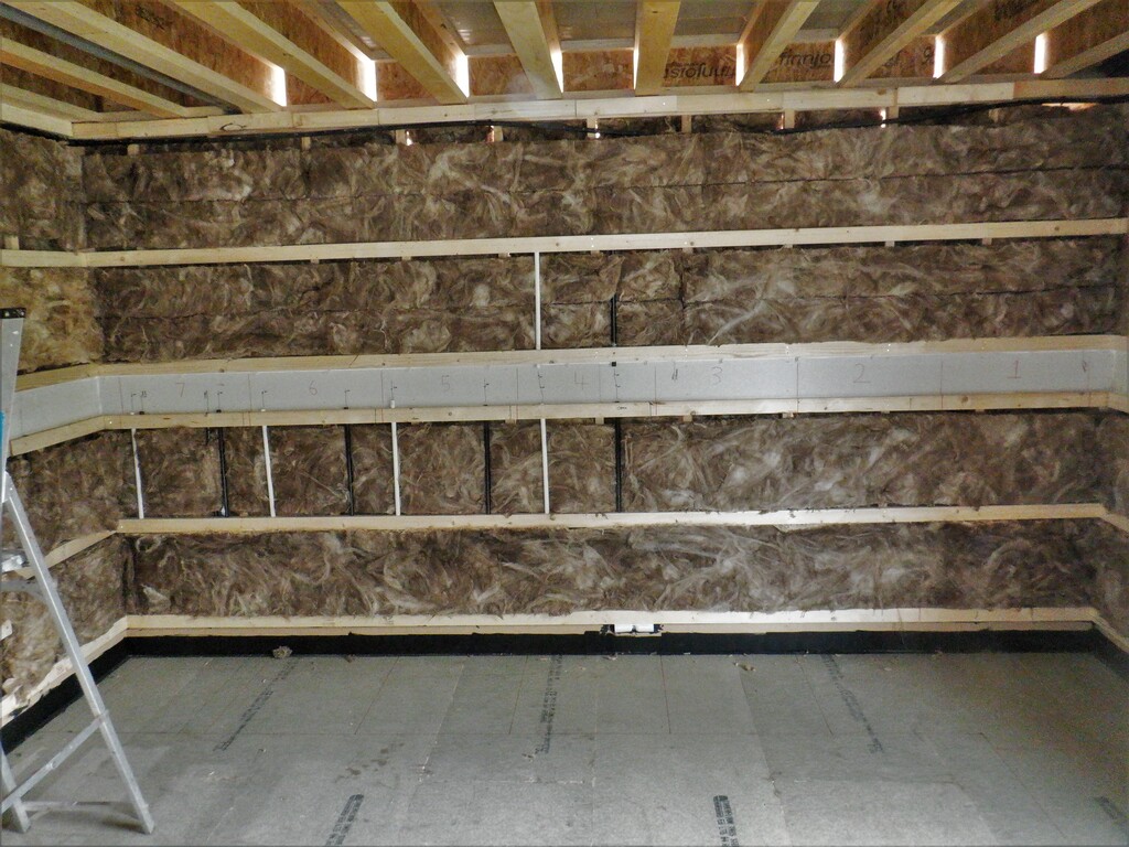
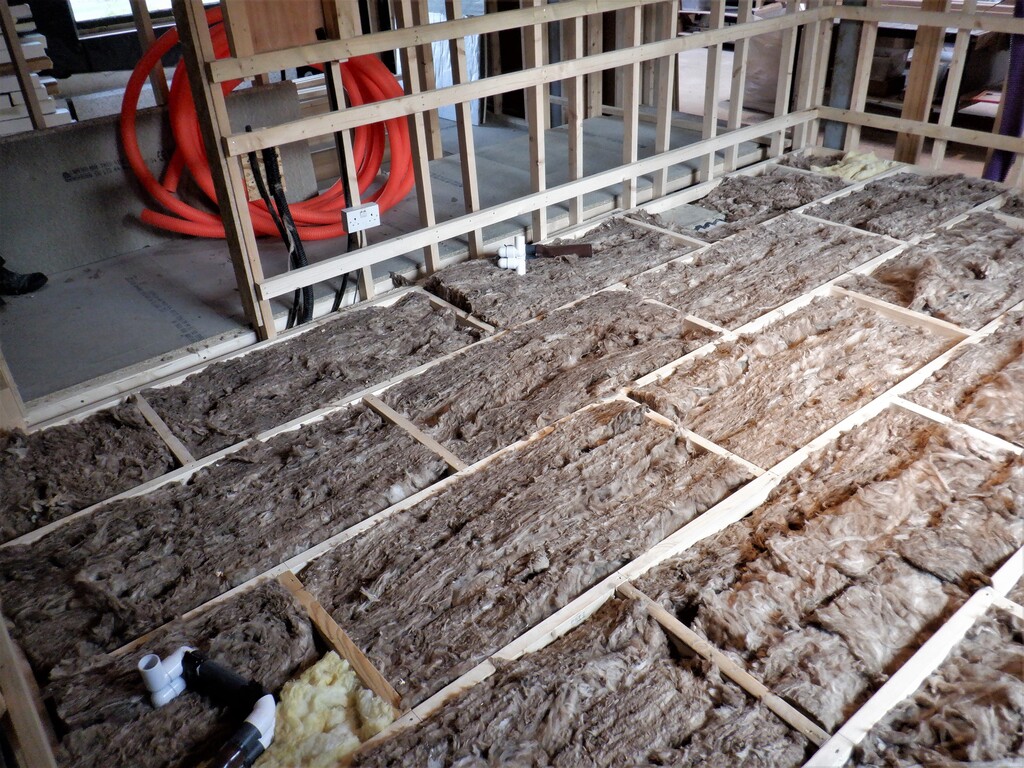
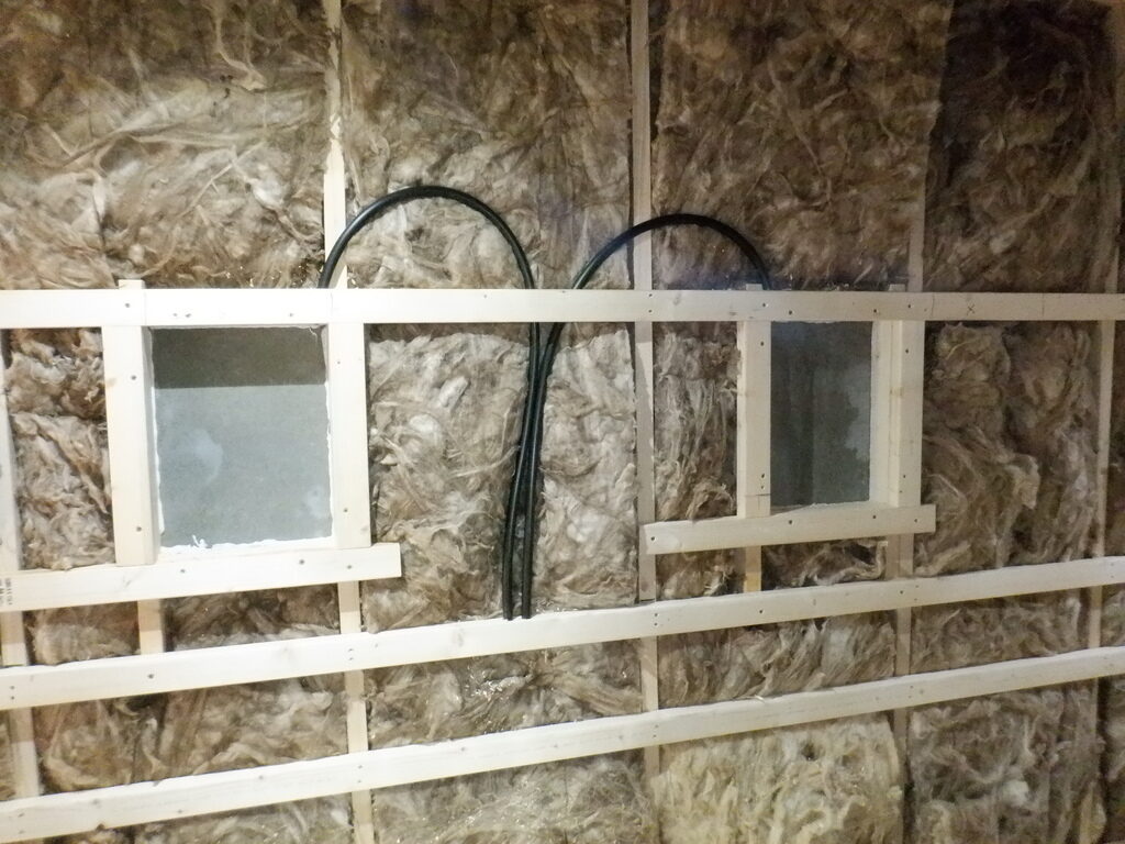
Finally, we layered in another load of glass wool strips, horizontally between the horizontal rails, using up two more rolls of 100mm thick wool. They are bulging well out of between the wooden rails, which is good as when the boards goes up, it will compress the wool down and improve the sound dampening qualities.

Insulation-in-the-halls
It is very interesting to how quiet and soft the sound is in our hallways at the moment, because of all the glass wool absorbing most of the sounds. This is what we are hoping for when we have finished.
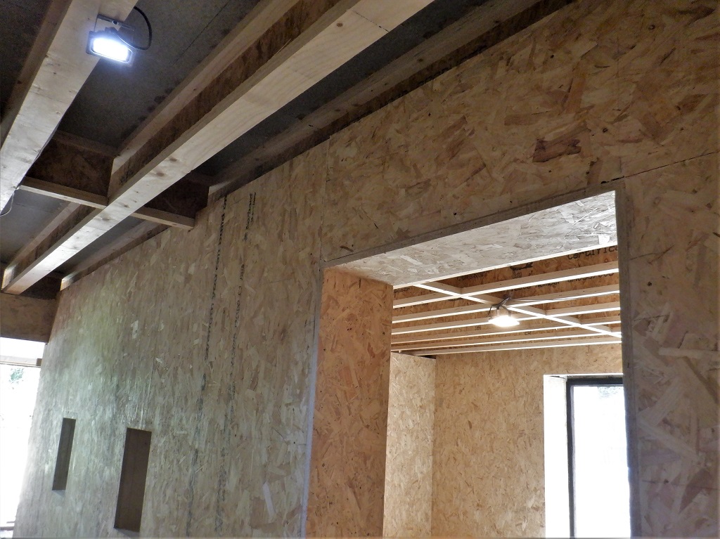
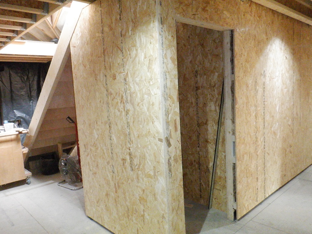
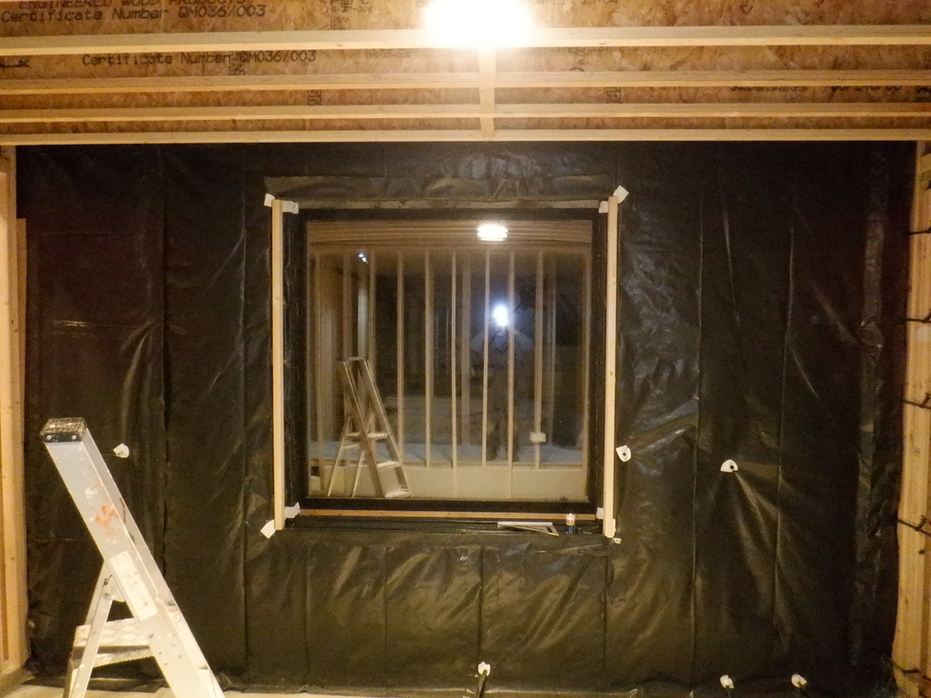
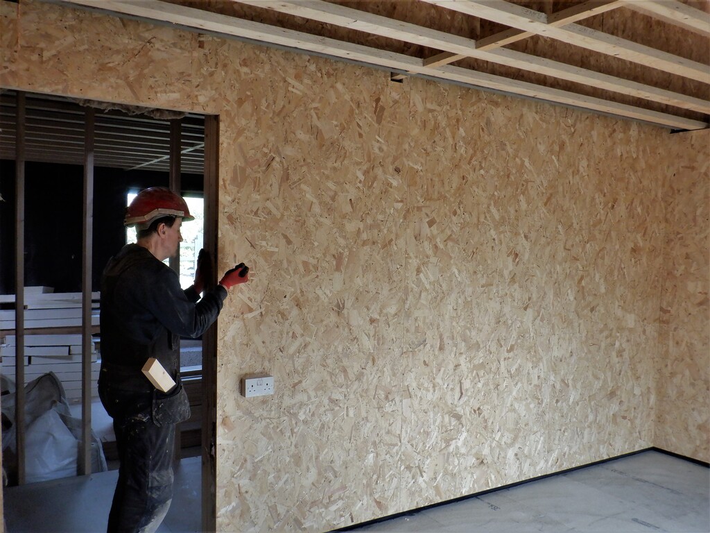
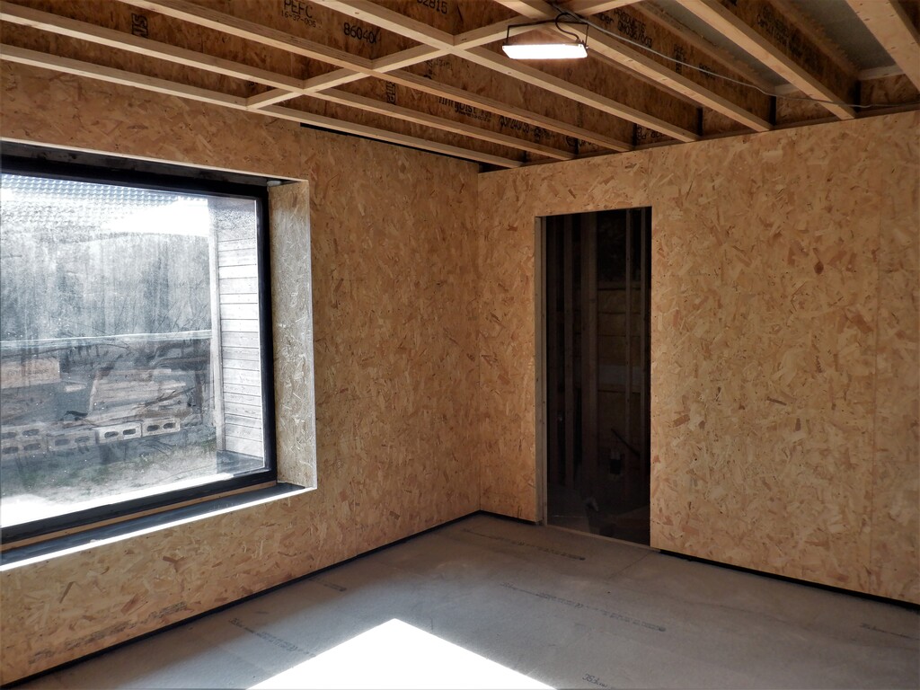
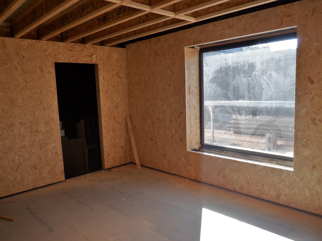
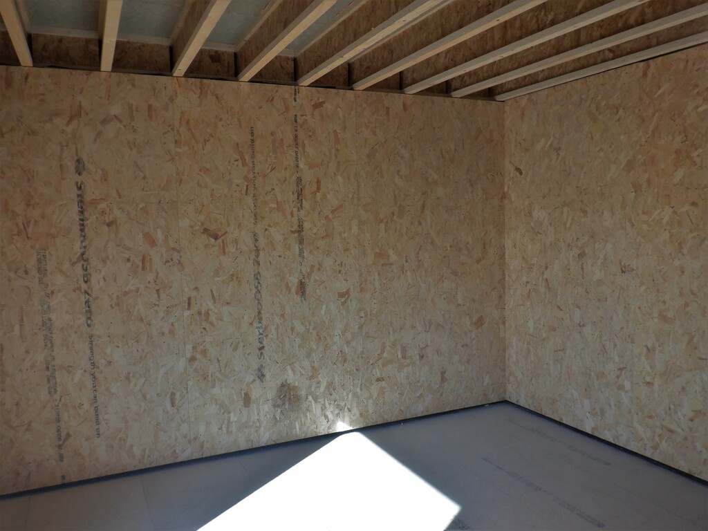
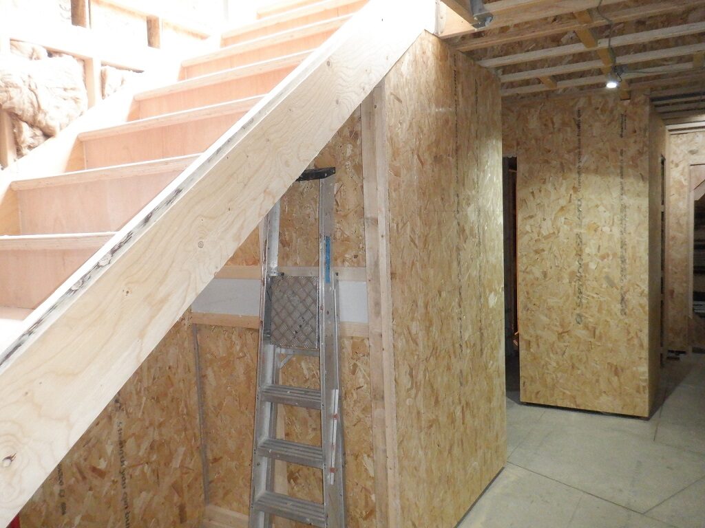
And .. at last .. we have put up the OSB 18mm boards, onto the framework, to finally make a solid walls along all our hallways, all four sections are now covered from floor to ceiling!
Plus also, we have cut out the Niches too, just to show those off too!
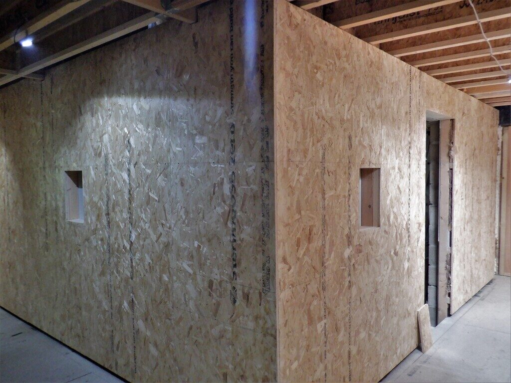
Halls-boarded-1
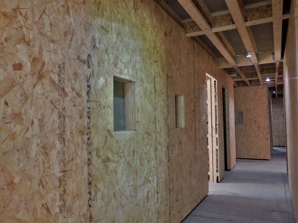
Halls-boarded-2
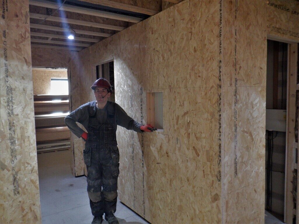
Halls-boarded-3
That concludes the construction of all the four Halls and here is a small video showing our ground floor layout etc.