Blog

  • Six out of Eight Rafters in “M” Section Completed!

    Today, we resumed our task of creating rafters, this time for the section along the “M” wall / roof area. We managed to do six out of the eight we got to do. We would have done seven and perhaps even all eight if we hadn’t had the interruption of a visitor coming this morning.
    It was the usual job of assembling the top and bottom flanges and the webbing into our template, gluing each side followed by a line of nails, flipping over and repeating this process again.

    Rafters-M6-to-M11-Made

    Rafters-M6-to-M11-Made


    We will do the final two in the morning and then start the job of hauling the dry ones outside and getting them up there into the roof framework. Let’s hope the weather will be kind to us!

  • Three Completed Rafters Now Up and Installed, Plus Extra Measurements Taken

    Today,we took outside the completed three rafters, these being the E6 and E7 as well as I6. It was the usual case of using our winch motor to lift them up, do a test fit, make any last minute adjustments and then glue and nail the rafter into place.

    Rafters-E6-and-E7-Installed

    Rafters-E6-and-E7-Installed

    Rafter-I6-Installed

    Rafter-I6-Installed


    Then we proceeded to take further measurements to get the distances for the “in-fill” sections on either side of the rafters (as they are the only full length rafters in these walls), the minimum and maximum lengths. We took down 2 pairs of measurements for the “E” section and another 2 pairs of measurement for the “I” section. All this then got entered into our spreadsheet which will calculate the lengths of all the remaining rafters needed to fill in these triangular areas of the roof.
    But the next step on Monday is to complete the eight rafters for the “M” section and then get them installed, hopefully, on Tuesday.

  • Completed Preparing for Next Batch of Rafters and Assembled Three Today

    This morning, we finished off preparing all the bits and pieces for making our next batch of rafters. We brought in 48 strips of the plywood webbing and proceeded to pair them up and slice the 32degree angled ends. Then eight pairs had the steel I-Beam (the large version) clearance slot put in, and the other three had the narrow version of the steel clearance slots. Plus a further 11 pairs had the wall top-plate clearance notches cut away. The final job before lunch was to chop up more internal straight noggins and some more little filler noggins too.
    After lunch, we exactly trimmed all the CLS timber pieces (that had the scarf jointed extensions) to match what the spreadsheet indicates. We brought in a heap of polystyrene foam strips and then vacuumed the whole workshop to remove most of the sawdust as possible and then finally got down to assembling the three rafters, which were E6 and E7 and the I6 rafters.

    Tomorrow, weather permitting, we will take these three completed rafters outside and installed them and get our workshop cleared, ready for the next eight “M” rafters to be created on Saturday.

  • Preparing the Pieces for 13 More Rafters

    Today, armed with our new version of the spreadsheet that now calculates everything from the basis of the measured bottom flange, we proceeded to bring in 15 lengths of 89mm CLS timber plus 11 lengths of the 63mm CLS timber. The first job was to cut the scarf joints in 12 of our 89mm CLS lengths and cut various pieces off another two lengths which are the extension bits to add to the scarf joints. These were glued and screwed together and left to set overnight. Oh yes, the other ends of these pieces had the bird’s mouth cut into them plus the angled slice off the end too.
    Next the heap of the 63mm CLS were also cut with the angled ends (still 32 degrees) and then turned around to then cut a precise length off of each one in turn according to our spreadsheet. These all form 11 rafters, 8 for the “M” wall, 1 for the “I” wall and 2 for the “E” wall. These are known measured lengths so we can assemble these ones and get them installed.

    Next-set-of-Rafter-Parts-1

    Next-set-of-Rafter-Parts-1

    Next-set-of-Rafter-Parts-2

    Next-set-of-Rafter-Parts-2


    Tomorrow, we will bring in 50 strips of our 400mm wide plywood strips from off the storage stack outside and cut the angled slices off the ends as usual and also cut the special shaped slots for the clearance of the steel I-Beam and for the wall and top-plate too. It was fiddly but we got there today and hopefully tomorrow we can start assembling complete rafters and get them ready for some to go up on Friday.

  • Last Two Rafters Installed on Roof “A” Section, Also Measured the Other Three Similar Roof Sections

    This morning, we tackled the next rafter, the A4, to slice the bevel on the end of it, analysing the results. It was still inclining to curve outwards during the sawing and we surmised that the saw blade was ever so slightly off line. So we attached a thin 1mm plastic spacer on the sled at the bottom left corner to try and offset this skewness. And yes it did seems to do the trick. We then did the next rafter, A5, and repeated the bevel slice and this time we got a much better cut first time. We are a little bit more confident of the machine now. The proof came when we took these two rafters outside to get them up and installed. We decided to try and man handle them up ourselves as we had a great advantage with these rafters as the wall ends fits like a glove and actually anchors the whole rafter into place. We only needed to hold the top end to relieve the strain and make sure we don’t accidentally break the Bird’s mouth joints.

    Roof-Section-A-Completed

    Roof-Section-A-Completed

    We fixed them the same by screwing a 8mm coach screws, one in the bottom and one in the top of each rafter and also glued of course too! It went very well and flat against the PA diagonal beam which further enhanced our confidence that the Bevel Slicing Machine is performing better.

    Then after lunch, we went around measuring the other similar sections of the roof, namely the “M”, “I” and “E” sections by moving the tall scaffolding tower around, as all are having the same 32degrees slopes. During this task, we were concerned that we were getting spurious misleading measurements along the top flange distances because our template was not going flat against the Kerb of the Skylight and this was proven when we placed the spirit level on the template and the position of the Kerb was slightly proud of the steel webbing underneath. This caused us to reconsider and switch over to measuring the bottom flange distances instead as we realised that this aspect of the rafter element is much more “stable” and the main structural load points is on the bottom flange at the top and the shape of the wall end (the top-plate and legs) are much more accurate to where the Bird’s Mouth goes. So we took down a series of distances to then enter into our spreadsheet, ready for preparing the elements of the rafters in our workshop tomorrow. There are 10 more long rafters to make and a heap of the bevelled rafters to fill in those corners of the roof sections.

  • A1 through A3 Up and Installed

    Our new week started with us making a second saw guide template for doing “right-handed” Bevel slices.

    Next we serviced the Bevel Slicing Machine and made sure that all the nuts and bolts are tight and locked against vibrations by using thread lock glue (similar to superglue) and also mounted a handy wooden block on the base to aid in keeping better pressure on the sled platform and also against the guide rail too.
    We then proceeded to do A2 and A3 at the sharper angle of 52.5degrees (this set of rafters are joining to the PA diagonal beam) and the first one, the A2, went through quite well. We had problems where the saw blade started curving outwards but it seems to be ok. But for A3, it did show this problem again but not so much. We think perhaps, that it is doing a lot of work and the original motor and gearbox specs were only for smaller diameter blades and we may be overstressing it. we will try and slow down the speed and perhaps do short spurts of cut and draw back and approach back in again in a series of small movements. We tidied the end with the Planer.
    Then we took these finished rafters outside including A1 (which is just a single CLS timber without any webbing) and got them up and installed. We remembered that these rafters needed to be 10mm sticking proud up above the edge of the PA diagonal beam.

    Rafters-A1-to-A3-Installed

    Rafters-A1-to-A3-Installed


    These three rafters fitted quite well but we did decide to switch over to 6mm coach screws instead of nails as the screws had the extra advantage of pulling the sloping joints in nice and tight and the glue was squeezed out.
    Tomorrow, we will do the other two rafters, A4 and A5, to finish off the “A” Wall / Roof section and then move on to do the “E” and “I” Wall / Roof sections.

  • A18 through to A22 Are Up and Installed

    Just before lunch, we tried out our new Bevel Slicing machine for the first time on the smallest rafter A22 to see how it went. The machine and template performed very well, we are glad to say! We took out this little 1 metre rafter outside to test fit it and it went in not too bad. it was slightly too long but that was because the original finished rafter ended up being 4mm longer than expected, which included also a local variation in the Kerb section of the Skylight.
    After lunch, we removed these 4mm off the top end of the rafter and tried again and it fitted much better this time. we went along with our spirit level to test the kerb side of the skylight to see if any more had more than usual variations but the rest were within tolerance.
    We then used the Bevel Slicing machine on the next rafter, the A21, but double checking the length first which turned out to be ok. This rafter was test fitted as well and it was fine straight away. We decided at this point to bring out all our tools and glue etc. to install these two small rafters up so we did that, applying the glue and then nailing them tight into place. We carried on with the longest rafter, the A18, next and got that one up into place first time too.
    The rafter A19 and also A20, proved to show up some problem with our Bevel Slicing machine where the saw blade seems to be bending away from the straight line and we don’t know why this is happening. We had to finish off the bevelled ends using our power planer. We got these two final (of this local section of the roof) rafters up and installed.

    Rafters-A19-to-A22-Installed

    Rafters-A19-to-A22-Installed


    It was quite dark when we finished, especially after we have brought in all the tools, compressed air equipment, wrapped up the lift winch motor again and tidied up after ourselves! We left the tall winch support pole in the tower, sandwiched between rafter A20 and A21 and we will deal with that on Monday.

    As you can see, we hope we can get the tower from out among the rafters .. or we will be in trouble! – grin!

  • Bevel Slicing Machine Is Completed

    This morning, we concluded the creation of the new Bevel Slicing machine with the addition of of a G-clamp to anchor the required angle for the bevel.
    Then we created a much simpler guide template that fits over the end of a rafter and provide both a starting platform to rest the saw machine and then another platform on the other side to receive the saw machine as it comes through the cut to arrive safely without falling off or anything like that.

    Bevel-Saw-1

    Bevel-Saw-1

    Bevel-Saw-2

    Bevel-Saw-2


    The guide rail (a flat 89mm CLS timber) has an extra thin strip of wood to make sure that the saw machine on its sled won’t tip upwards.

    Angled-guide-for-bevel-saw

    Angled-guide-for-bevel-saw

    Bevel-saw-on-guide

    Bevel-saw-on-guide

    Sawn-Bevel

    Sawn-Bevel


    This template is only suitable for 32degrees angled ends and orientated to the left direction. We will have to adjust or make another template to do the right handed orientation, until we have finished all the rafters that has the 32degrees ends on them.

  • Bevel Slicing Machine Designed and Nearly Finished!

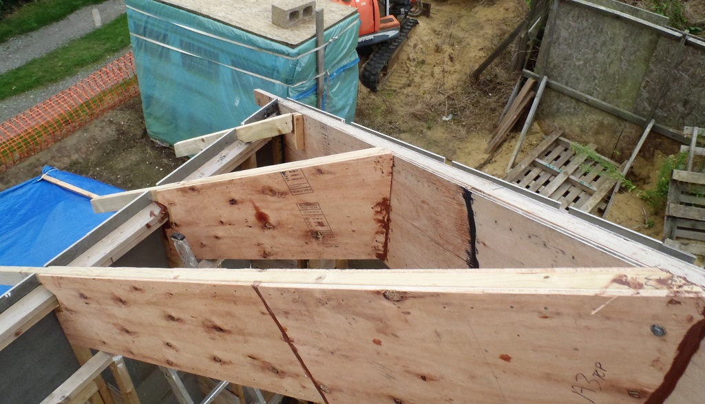
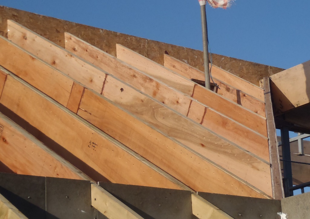
    Today, we turned to making a new tool to help us slice angled ends to a certain number of our rafters that needs to fit up against diagonal hip or valley  beams in the roof.

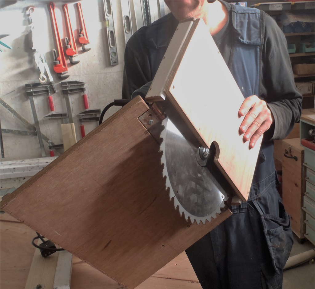
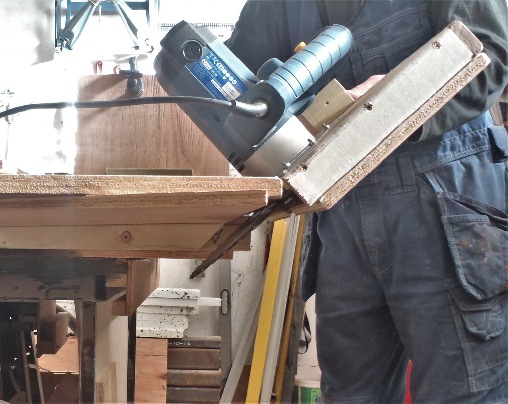
    We took an old portable electric circular saw and cut away the original blade shroud to allow a much larger diameter blade to be fitted. To this reduced metal plate, we mounted a sheet of plywood that is bigger than the new blade (300mm diameter) and then put a half a box over the upper section of the exposed blade to protect us from the spinning teeth!!

    Bevel-cutting-machine-Day-1

    Bevel-cutting-machine-Day-1


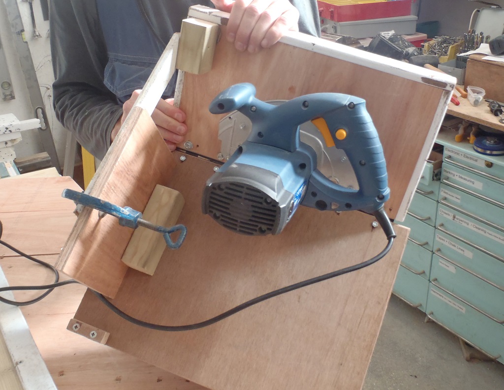
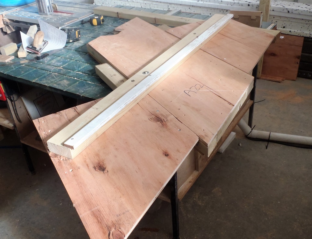
    We then put on a double hinge near the bottom of the saw machine and mounted a thick 18mm plywood base which will serve as the sled to run across the surface of the rafter, with an arm sticking out so that it can be fixed down to achieve the desired angle we need when slicing the bevels. We can now get any angles from a minimum of 22 degrees and go all the way up to an impractical angle of about 85 degrees! We only need to get to 60 degrees for our maximum angle!

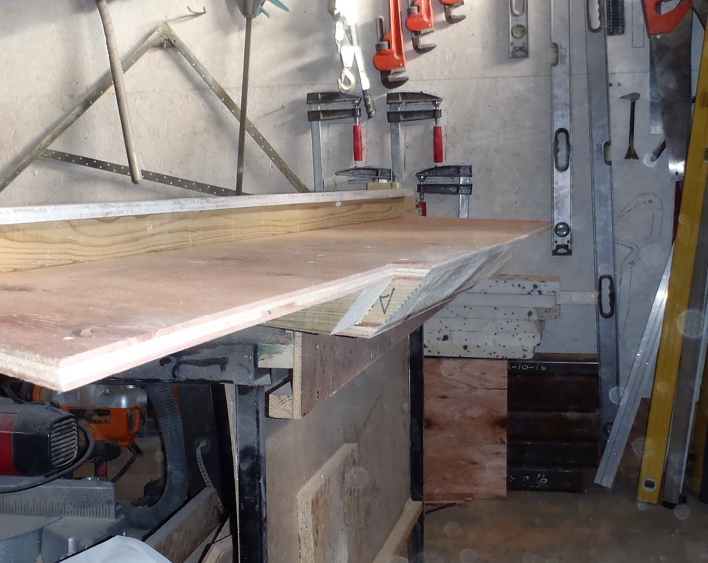
    The second part of the machine is a template to fit onto a rafter which will provide the support and guide for the sawing unit. We wanted to have the template to flip around from doing a left handed cutting to a right handed cuts without having to unscrew and refit various parts. The design calls for a parallelogram aligned set of bracing arms (to hug the edges of the rafters) and the second set to provide the guide for the saw unit itself.

    But it proved to be very difficult to get everything exactly measured and aligned. We tried several different methods and measuring schemes to position the mounting screws but we couldn’t get it working.
    So tomorrow, we will have a rethink and come up with a much simpler design and just work with the main premise of just needing a straight guide for the saw unit, set for the required angle and also parallel to the end and then clamp or screw it to each rafter in turn. Perhaps have a second one made to do the flipped around cuts. We will see what comes out with a night of sub-conscious thinking!

  • The Nine Rafters Created for Roof Section “A”

    Today we got down to assembling all the bits and pieces into nine rafters that form the last sections of roof adjoining the “A” wall. We did three this morning (in two runs) and the remaining six this afternoon (in 3 runs). We used as much of the template as possible to maximise turnaround time. Each pair (one smaller and one larger) went into the template and then each side was glued and nailed, using our squeezer and nail gun as usual.

    The-rest-of-A-Rafters-are-Made

    The-rest-of-A-Rafters-are-Made


    The next job is to build a bevel-cutting saw machine that can be rotated and angled and positioned on the end of each rafter and power cut our way through all the layers of the plywood and CLS timber composite. We cannot use a standard off-the-shelf circular saw as none can angle more than 45 degrees and over half of all bevel cuts are beyond that limit, so we are having to make a temporary tool that is specifically designed to fit over the ends of these 400mm wide by 62mm thick rafters and clamped into place to allow the saw to slide across the end. The other limitation of domestic saws is the limited size of the saw blade themselves and can only cut no more than 50mm at the larger tilts. We need to do at least 100mm so we have bought a 300mm wide blade which will give us a maximum cut depth of 125mm. That is tomorrow’s job to design and build this machine!! A lovely Engineering problem – Grin!