Category: Build Progress

  • Top-Plate on Wall Doubled Up

    Today, we went around sticking down the second layer of the top-plate on the wall. It is the 89mm wide timber to sit on the outer post that forms the exterior wall structure. We used the 3D printed glue applicator we made last week and it worked very well!

    Second-top-plate-glued-on

    Second-top-plate-glued-on

    Then after that, we took 20 sheets of cement boards and one by one, routed a groove into one edge on 13 of them and then did both a groove and tongue edges on the next 7 sheets.

    They are all now sitting on our trolley ready for installation tomorrow.

    Cement-boards-ready-for-last-row

    Cement-boards-ready-for-last-row

    We had a a surprise discovery this morning when we came across a nest balanced rather wobbly on a small heap of loose planks of timber, high up inside our exterior wall. It was an open twiggy type of nest with one small pure white egg about 15mm long in it. There was no noticeable bird hanging around but we made sure we didn’t disturb the nest too much and left it there. We hope the bird (possibly a Dove) will come back.


  • Second Strip of Cement Panel Now Up On Wall

    These last two days, we have created lots of narrow strip of cement boards, and then nailed and glued them up on the exterior wall to build up the second layer of the weather and fire resistant cement panel coverings.

    Cement-board-strips-cut-and-routed-one-edge

    Cement-board-strips-cut-and-routed-one-edge

    Second-row-of-cement-boards-up

    Second-row-of-cement-boards-up


    We first took 7 sheets of cement boards, sliced them down into 275mm wide strips (producing 28 pieces), and then passed them through the router on both long edges to form a groove and tongue edges respectively. After that, we went around starting at the front of the building in the Utility Room corner, and then worked clockwise round the perimeter of the building, skipping the doors and windows as before. We finished with just one complete strip left over and lots of smaller pieces – that was close!

    Tomorrow, we will go around gluing and nailing the second layer of the top-plate timber on top of the wall, both the 89mm width timber on the outer leg and the 63mm width timber on the inner leg, and at last, we will do the third line of the cement panel to complete the whole wall.

  • Completed Timber Support Framework on Steel I-Beams

    With the wind picking up a bit on this clear Monday morning, we resumed going around the steel I-Beams and installing the timber support pieces.

    Timber Rafter-Supports-on-other-side

    Timber Rafter-Supports-on-other-side

    It is virtually the same as the work we did on Saturday and we now have completed the full circuit.

    We have a line of wooden timber pieces on top of the steel work and a complete loop of special  timber pieces with slots sliced into them, fixed down on the lower flange, ready for the roof rafters to go in.

    Tomorrow, we now can resumed doing our cement board wall coverings, first putting up a narrow strip and then the 3rd line of full height 1200mm cement sheets to complete the wall covering and structural racking.

  • Installation of Support Timber Framework on Steel I-Beams

    Today, in glorious sunshine, we started the task of mounting all the special timber pieces we made in the last week, and putting it up on the steel I-Beams.

    We also put the extra flat pieces of timber on top of the I-Beams as well. Each section of the steel framework was scrubbed with water and a little bit of detergent to wash off the dust and bird poo, then measured and cut each piece of timber to fit into place, using our laser alignment tool to accurately get the special timber pieces down on the lower flange and a regular rectangular timber piece on top of the upper flange.

    Timber-rafter-supports-Fixed-in-place-1

    Timber-rafter-supports-Fixed-in-place-1

    Timber-rafter-supports-Fixed-in-place-2

    Timber-rafter-supports-Fixed-in-place-2


    We used our special all weather construction glue to stick the timber onto the steel surface, using lots of mechanical clamps to squash the joint tight before locking it down with 5mm x 50mm long screws (we had previously pre-drilled clearance holes in the steel ages ago).

    Today we managed to get exactly half way around the steel framework and we will continue on Monday and get it completed. After that, we will build up the Sky Light framework on the newly fitted timber supports and this will provide the structural anchor points for the roof rafters, hence why we are having to do all this now.

  • Timber Rafter Supports for Steel I-Beams Created

    Over the last few days, we have been cutting, slicing and routing a whole series of timber pieces that will provide the fixing points for the ends of the roof rafters up on the Steel I-Beams.

    There are three basic sizes for the different parts of the steel work as follows:

    • 2 ends which has a 40 degree angle sliced @ 61 mm from a 75 mm by 50mm wide timber
    • 6 lengths with a 32 degree angle sliced @ 117 mm into from a 150mm by 50mm timber pieces
    • 8 lengths with also a 32 degree angle sliced @122 mm from a 150mm high by 50mm thick timber.

    The differences is the height of the slots that have been routed in. The end result is that when the roof rafters are placed into the slots, the top edge of the rafter all lines up, thus creating a levelled roof. The steel I-Beams comes in two sizes and thickness hence why we needed to have difference sizes.

    Rafter-lower-supports-on-I-beams-1

    Rafter-lower-supports-on-I-beams-1

    Rafter-lower-supports-on-I-beams-2

    Rafter-lower-supports-on-I-beams-2


    We had to make a template to route the 10mm deep slots, all done at the correct angle, one at 32 degrees and 40 degrees.

    Now we need a dry day to go out and fix these pieces on to all the steel I-Beams all the way around. We will align up each piece using our laser alignment module (this sits on the top of the walls on a leg and the laser sends a beam up to the steel work). But first, we would have to clean the bird poo off before gluing and clamping the timber into place – grin!

  • All Window and Door Sub-frames are now Complete

    Back to work after two days of interruption’s , we resumed the task of putting together the Lintels and Framework around all the Windows and Doors.

    We had 7 more openings to finish off where the short vertical studs are put in above the Lintels and got those done just before lunch.

    Then we fetched another five lengths of the 89mm CLS timber off our pallet (we have virtually used up one of the two pallets bar 2 lengths!) and brought them in our workshop to be chopped into:

    • 9 x 1711 mm pieces
    • 2 x 1100 mm (using the off cuts of above)
    • And 1x 480 mm piece (also taken from the left overs of above)

    We then ripped down the middle of the timber planks, to make equal sized (about 43mm wide) pieces. One would go on the bottom sill on all the 12 windows, and the other half went up on the underside of the lintel. These pieces are designed to allow us to have space for roller blind mechanisms to be fitted below and above the window unit.

    After lunch, we went around fitting all these half pint pieces on all the windows, trimming them down so they just fitted in nice and tight, glued into place and then screwed down in several places (four points for the widest windows, three for the medium sized ones and two fixing points for the narrowest).

    Final-parts-of-Window-Subframes-1

    Final-parts-of-Window-Subframes-1

    Final-parts-of-Window-Subframes-2

    Final-parts-of-Window-Subframes-2


    We finished off the day by dismantling one of our scaffolding towers and moved the 2 castors over to our existing tower to make it much easier to move around.

    The next job is to slice up half a dozen cement boards into narrow strips of about 300mm wide and go around the whole building putting on the second layer and after that, the final third layer using whole sheets again, but making sure whole sheets bridge completely over each Window and Door for maximum strength and racking, without any joints in the middle.

  • Starting to add the short studs between Lintels and Top plates

    In the afternoon we started to cut and fix the short pieces of timber which fit between the lintels over windows and doors and the top of the wall. These short studs will provide places to attach some of the roof rafters (rafters will be attached to nearly all legs). We completed 5 of the openings before stopping early for other commitments.

    Short-studs-between-lintels-and-top-plates

    Short-studs-between-lintels-and-top-plates

    Further commitments will mean no further work outside until Saturday but we will be ordering the LVL beams.

  • Done a survey of the Steel frame position.

    We started the day by measuring the distance from the steel frame to the walls at all hip and valley beam positions as well as selected other points. We wanted to confirm these distances so that we can order the LVL beams to make the hip & valley rafters at these points.

    To measure the distance we placed our very long ladder against the steel frame and stretched a tape from the steel to the outside of the walls top plate.

    Long-ladder-for-measuring-steel-frame

    Long-ladder-for-measuring-steel-frame

    We made 15 measurements  and we a pleased to say they correspond to the drawing within 50mm (mostly within 30mm).

  • Last Door Frame is Done and All Lintels Are In Place

    Today, under another glorious and hot sun, we finished off the final Door vertical framework (the Utility Room Back Door), which came out as 1041 mm to 1042 mm wide, in various places from top to bottom, this door will be a single extra wide style to allow better access for bigger items to get into our house.

    We then carried on with the next job of putting the Lintels over all the Windows and Doors. We measured and cut to size each opening, the two layers of 89mm CLS timber, glued and nailed together and also nailed down onto the vertical legs. There were 15 openings all to together, and we made sure that all of them were within 1mm to 2mm of being horizontal, putting in solid wooden spacers where necessary to make adjustments.

    Door-sub-Frame-completed-with-Lintels

    Door-sub-Frame-completed-with-Lintels

    Window-sub-Frame-completed-with-Lintels

    Window-sub-Frame-completed-with-Lintels


    Tomorrow, we will first measure the long diagonal rafters that forms the valleys, hips and ridges of our roof, so we can double check against our drawings to know exactly what we need to order from the specialised timber manufacturer, the man-made laminated veneer lumber called LVL. This material is basically lots of thin layers of wood, just like plywood but 200mm thick and can come up to 12metres long – wow! After that piece of survey work, we then carry on with putting in all the vertical short studs that connects the lintels to the Top-Plate, and once this is done, with one or two other little jobs, we then can continue putting up the second line of cement boards!!

  • Windows and Doors Framing Progresses

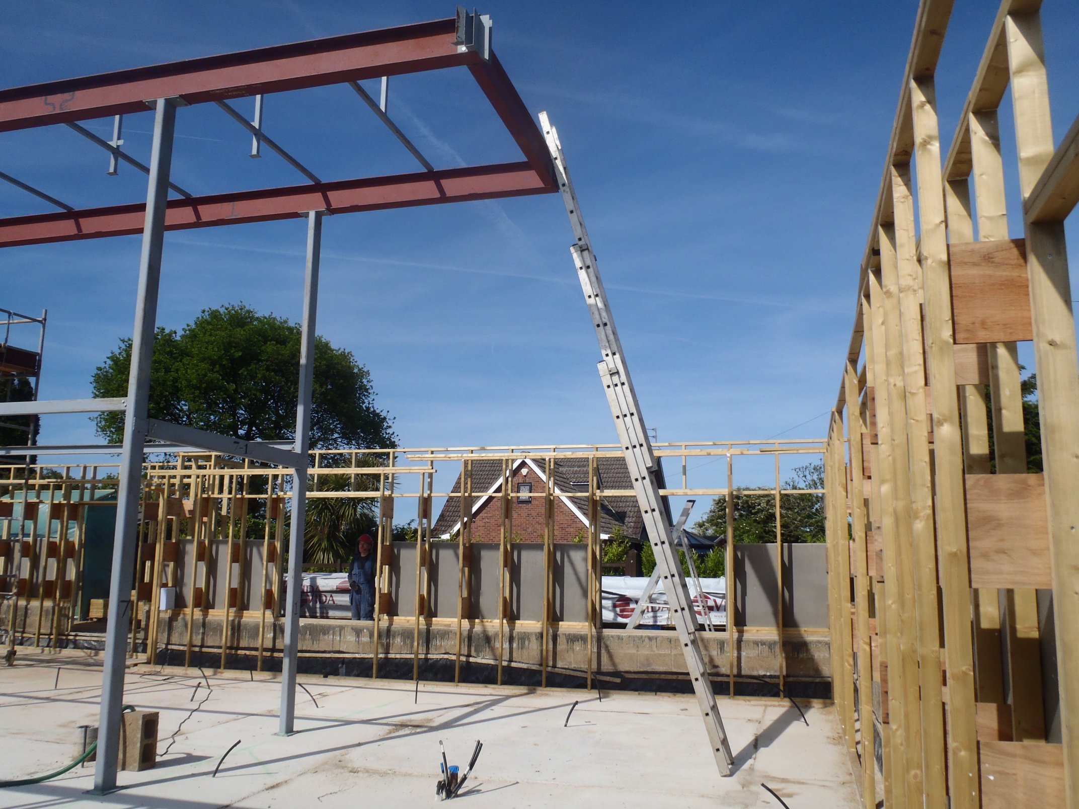
    On this lovely warm Monday, we carried on adjusting, gluing and fixing into place the remaining six window subframes going around the Great Room, the Kitchen and lastly the Entertainment Room. We had our framing template which is exactly 1708 mm wide so that all our 6 foot width windows will be the same. We then did the two 4 foot windows (the side of the Great Room and the Utility Room) making them both 1098 mm wide and finally, we did our only 2 foot window in the side of the Front Door extension and that measured 480 mm wide.

    Last-window-framed

    Last-window-framed

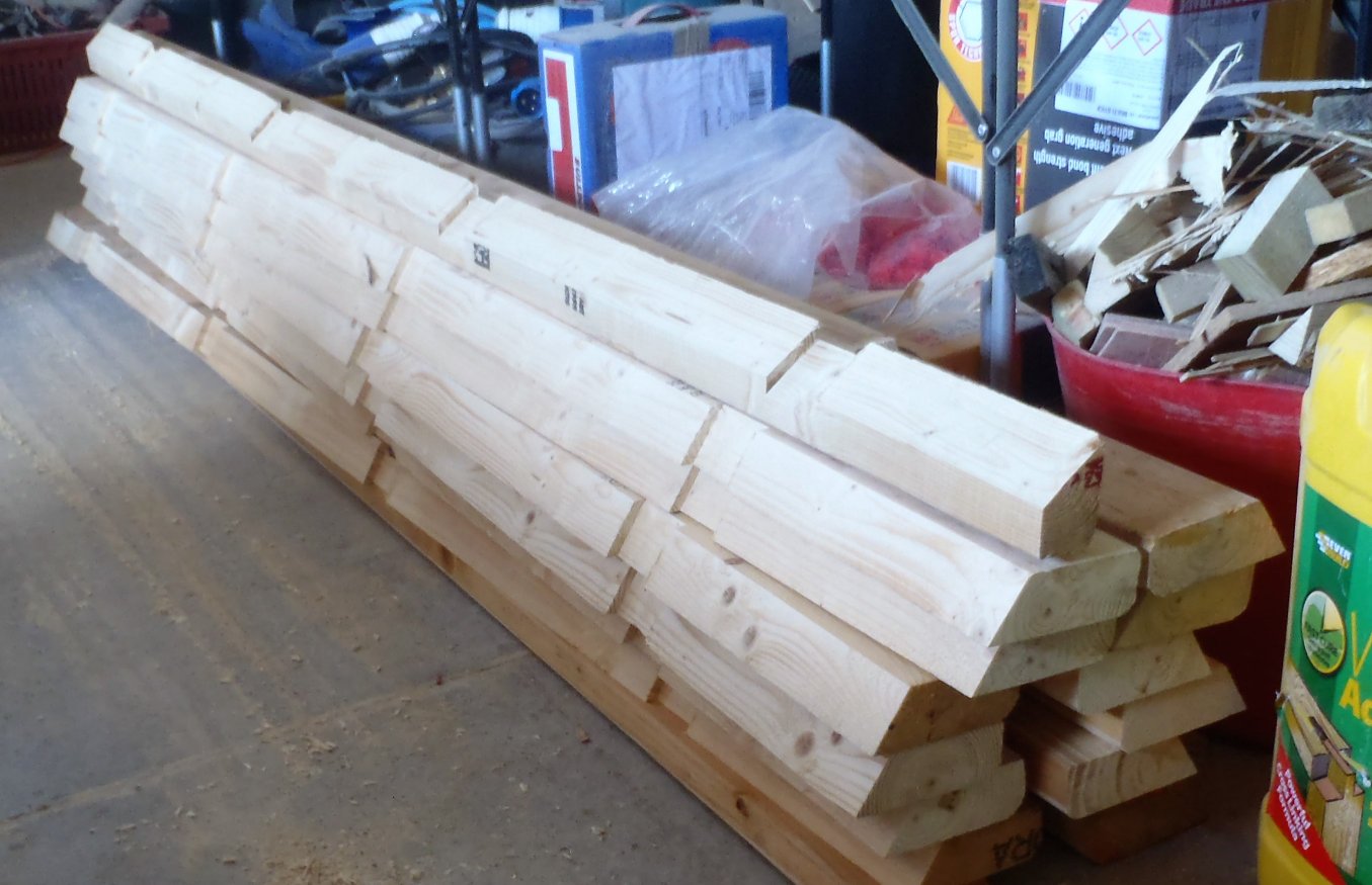
    The next job was to cut and frame the three doorways. They would need a height such that the top of the doors is the same as the windows so the calculations for this resulted in pieces of the timber to be 2252 mm long. We pulled out 3 lengths of our treated 89mm CLS timber and chopped them down to that size, but we noticed one of the timber being rather warped so we fetch’d another length from the pallet! We drilled 4 fixing clearance holes in each of the timber pieces, a clearance 8mm hole for the 100mm concrete screw and 3 x 5 mm holes for the ordinary 80 mm wood screws.

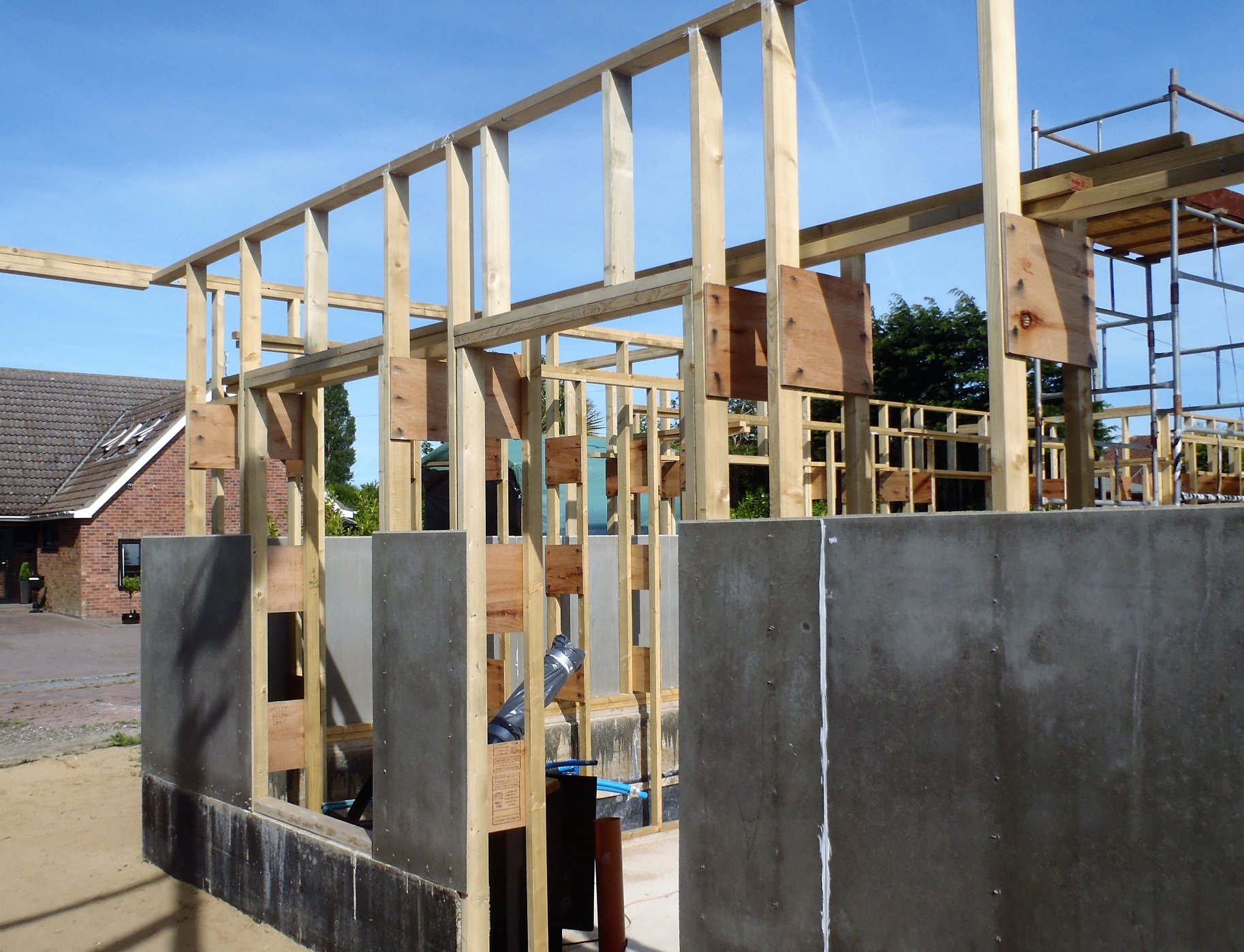
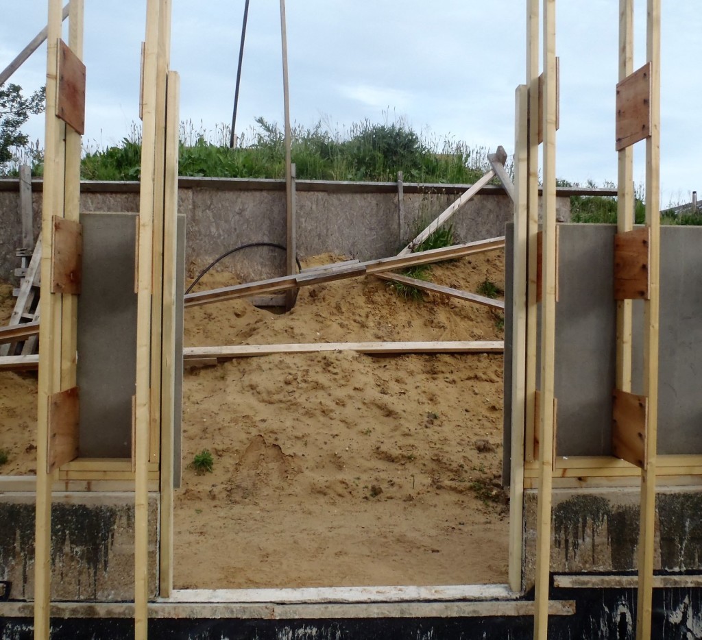
    Taking the 6 pieces out, along with the SDS drill, spirit level, screwdrivers and glue etc. We started with the Great Room-Conservatory French style doorway and fixed and fiddled the two vertical timber pieces into place. It took quite a while for doing all of it, like drilling the concrete holes, getting the spacers in and out and finally getting both sides vertical. We then measured the gap or width of the doorway which turned out to be 1491 mm to 1493 mm in various levels from bottom to top.

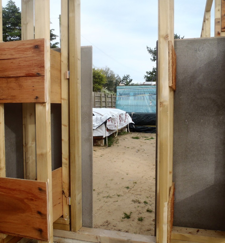
    We moved over to the Front Door and repeated everything again and the measurement this time came out at 1495 mm to 1496 mm wide. We were not concerned with this slight difference because these two doors are different styles and both are unique.

    Comservatory-Door-framed

    Comservatory-Door-framed

    Tomorrow, we will finish off the third and final door, the Back Door, and move on to the next job of putting in lintels over all the openings, both windows and doors, all 15 of them!