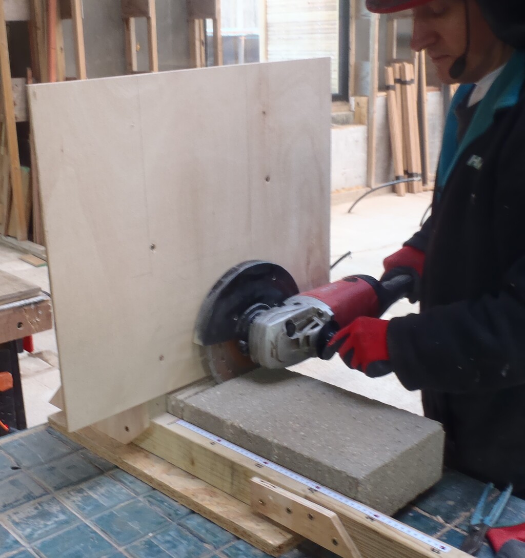
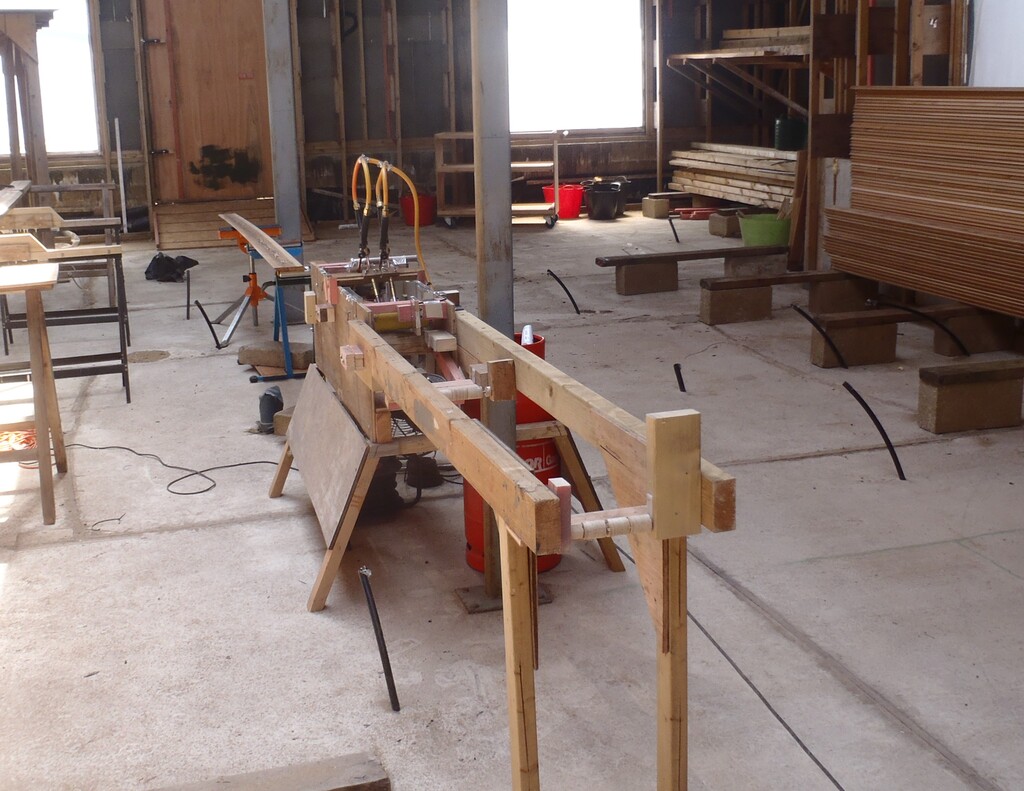
It took another three weeks to finish off tweaking the design of the scorching machine, with many iterative changes as we test and adapt the machine (As usual things take much longer than you expect, but I have enjoyed the change of work).
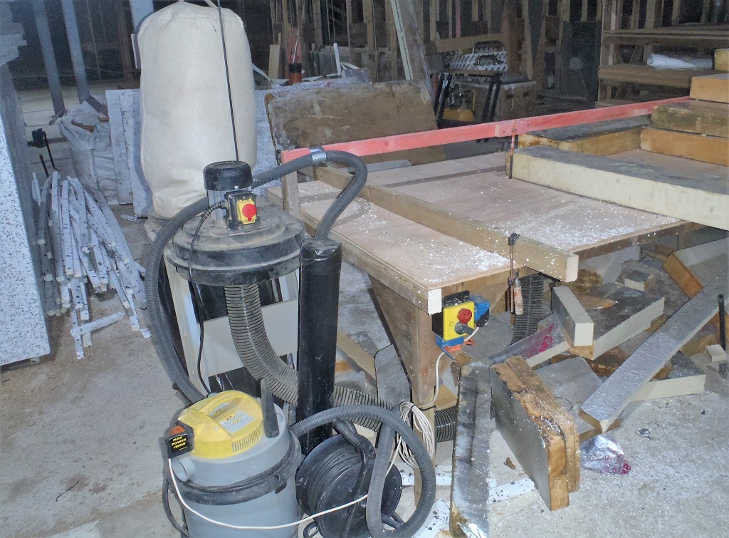
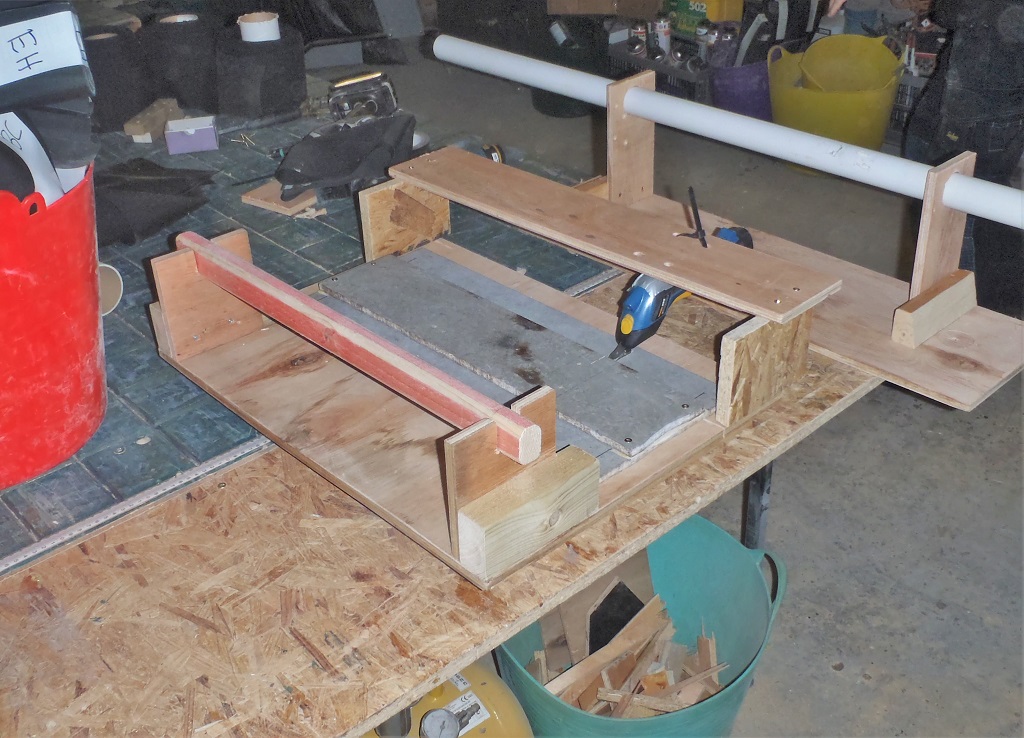
We started by moving the machine into the house (after cleaning up a bit), we then made a extension to the input side to guide and support the plank entering the machine.

Input-rollers-on-the-machine
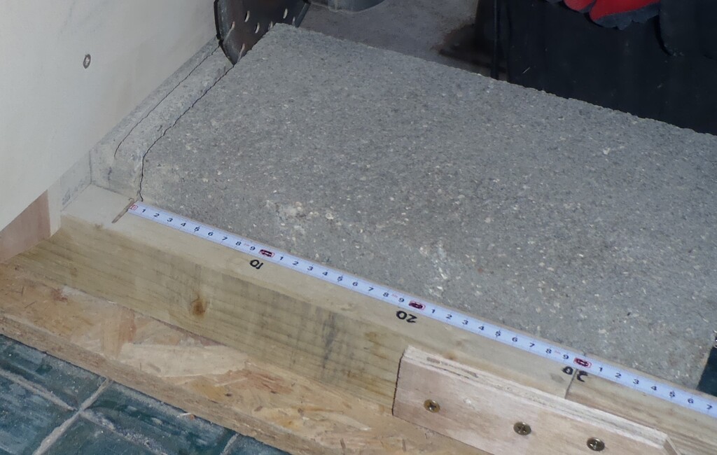
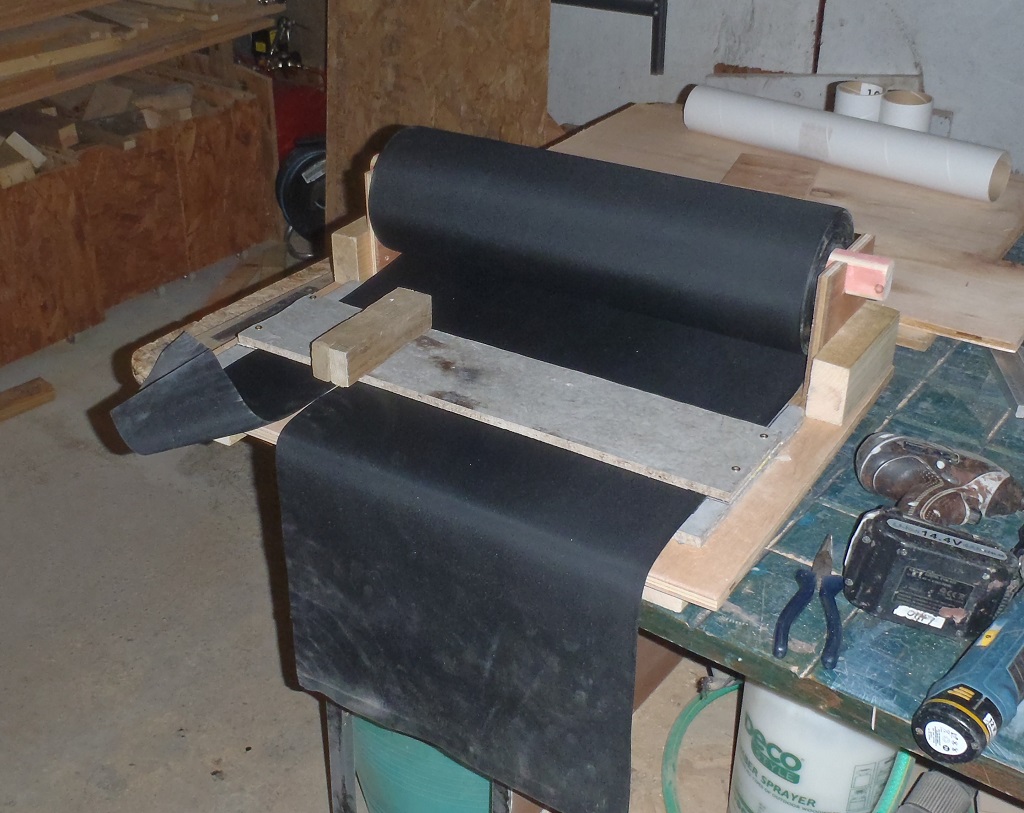
We did some test runs, and we can vary the amount of “burn” from a black highly charred finished to a gentle pale scorching. We have selected 5 levels of speed, all the way from a very slow 10mm per second (very highly burnt) to a much quicker 40mm per second to produce the pale finish. We also have the option of no scorching at all and this being our sixth level.
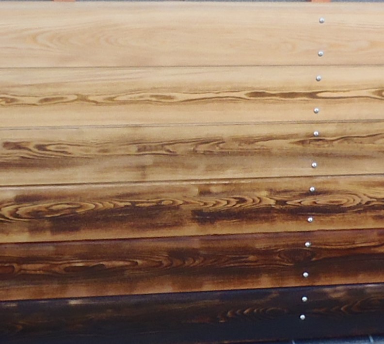
Our-six-scorch-levels
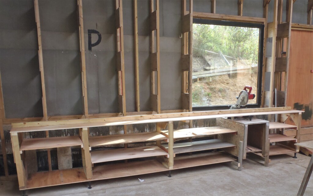
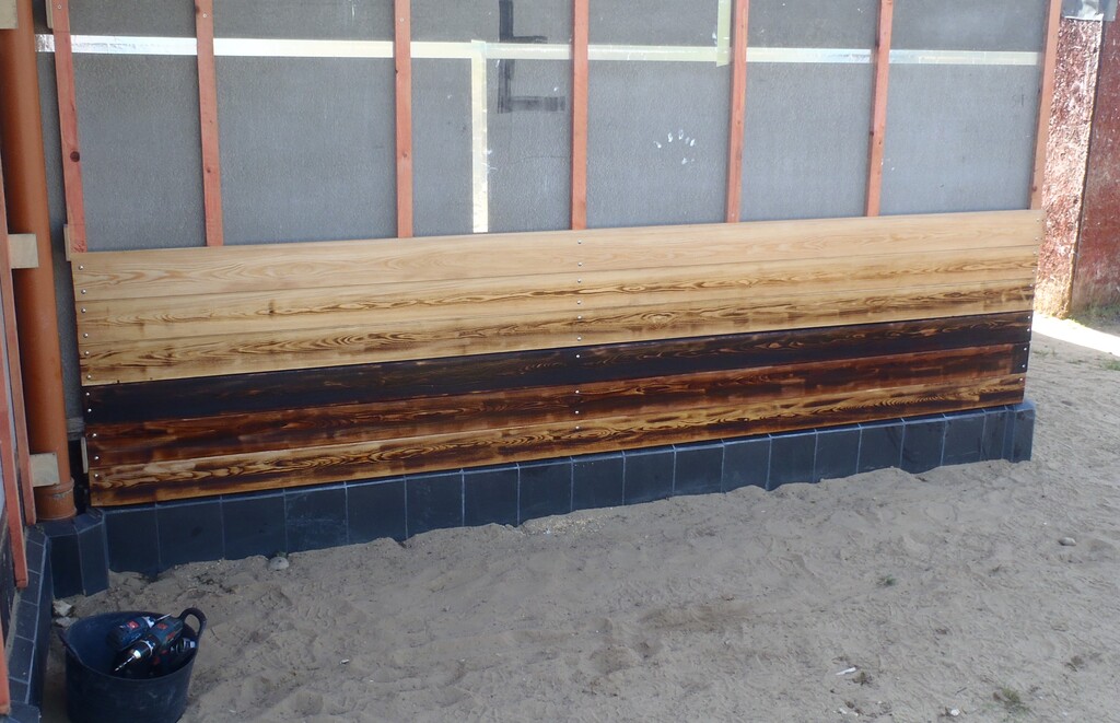
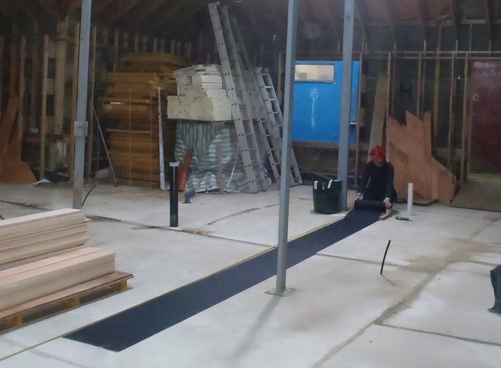
We put up a block of different burnt timbers on our house wall in the full sunshine to examine it and decide on what patterns we might like on different walls, taking into account their compass orientations, the windows sills and headers etc.
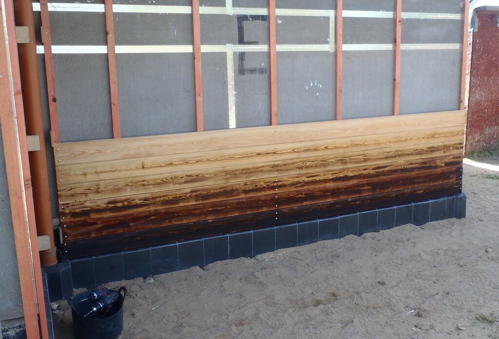
First-set-of-graduated-boards-on-a-wall

We-decided-to-flip-the-bottom-rows-
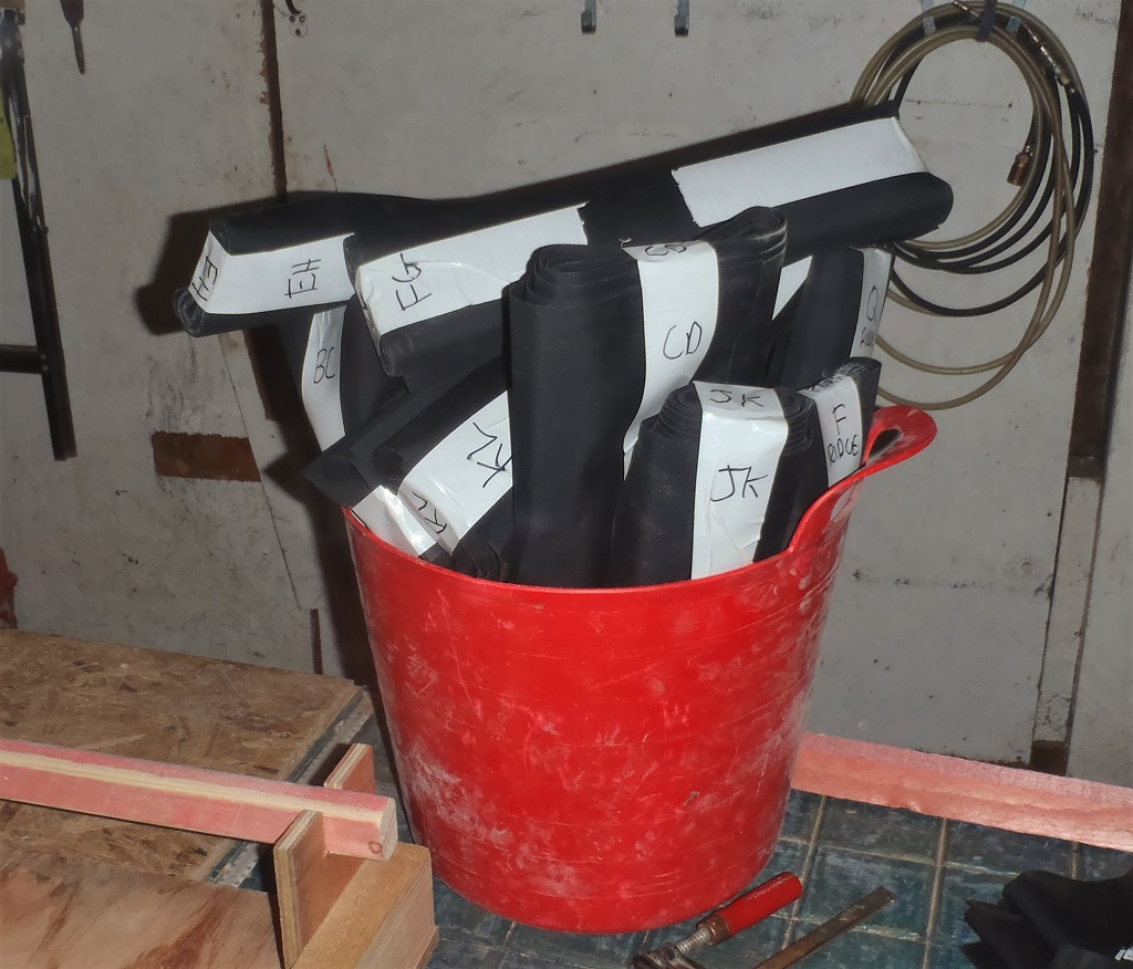
The next job was to build a spreadsheet of all our walls (fifteen of them), with their compass orientation, whether it is under a porch, then divide the wall up into three vertical sections (under the windows, beside the window itself and lastly above) to allocate what level of scorching is desired and then find solutions to the pattern of plank widths to fit into each section. This resulted in a table of quantity’s vs plank width and scorch level.
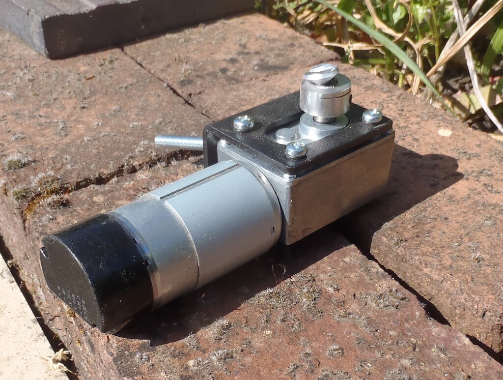
We started to process the wide planks first (they are nearest) and we had lightly scorched (#1) some planks when a plank got stuck. Shaun was running the machine whilst Stephen was wire brushing the finished planks so We did not notice for a while until Stephen looked over and saw the smoke poring out! We shut off the burners and when we examined the machine we found one of the motors had sheared it’s flexible connector…

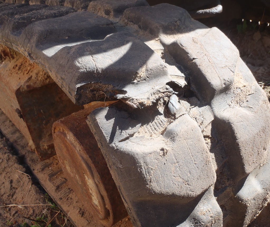
Drive-adapter-sheared-off
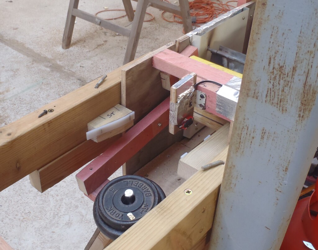
We repaired the machine and carried on but a few planks later we had a jam again (the plank sometime wanders off or bends), we caught this one earlier and no damage was done. At this point we decided (being nerds and all) that we would add sensors to the machine to detect any stall and sound an alarm. In hind sight we should just have carried on whilst keeping a good eye on the machine as getting sensors to work reliably took 2 weeks (but that’s hindsight for you)!
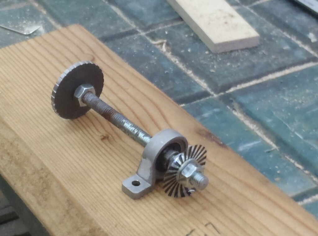
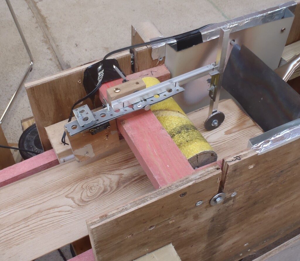
The machine needed to know 3 things – When the plank enters, when it leaves and if its moving. The first two should be simple just put a switch near the plank to be pressed when the plank is in. The movement detector devised initially was a metal wheel on a shaft which had a sensor measuring the shaft rotation, the shaft being mounted on a pivot which kept the wheel in contact with the plank.
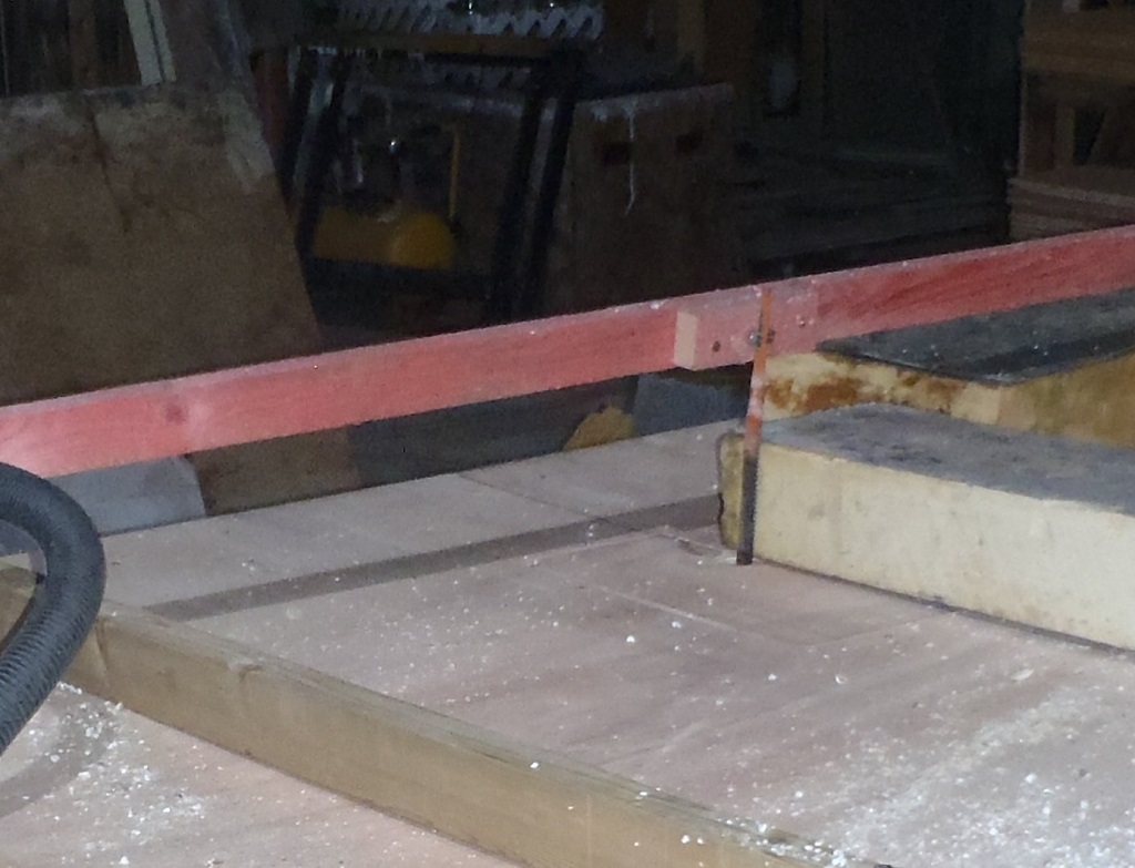
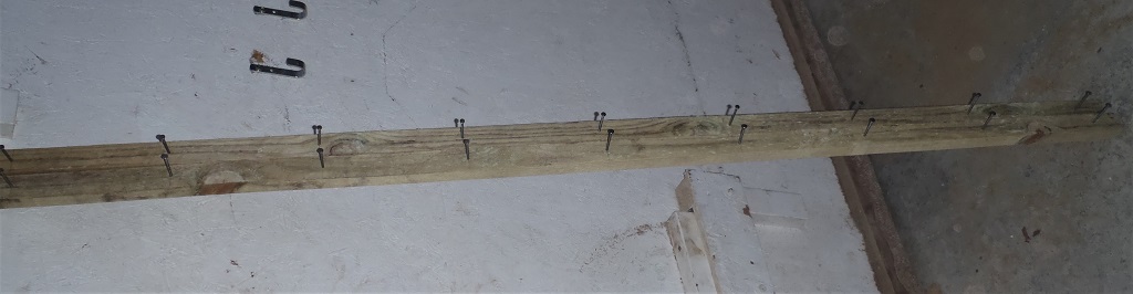
Input-plank-sensor-switch

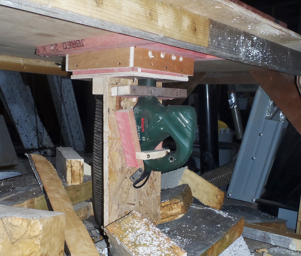
Rolling-encoder-mechanism
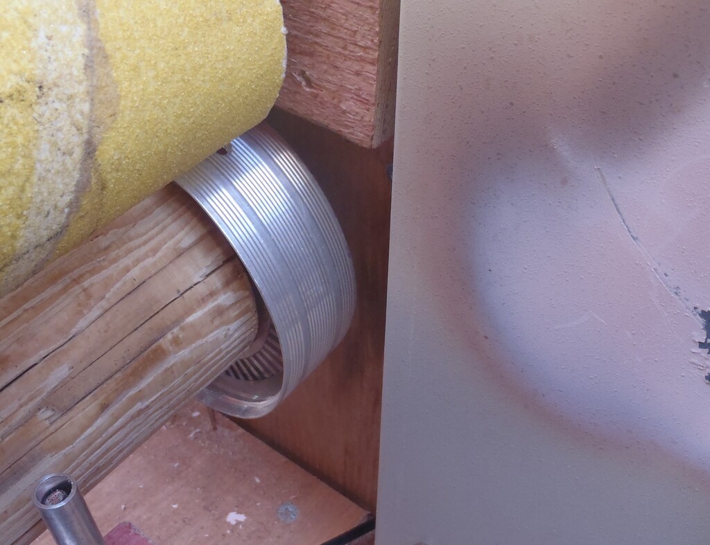
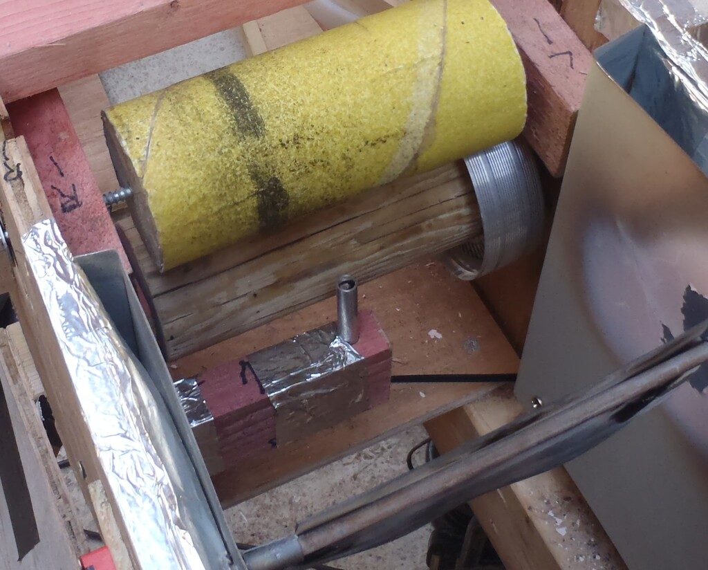
So having built the sensors and fitted them it took a day to write the software to run the machine and start testing. The metal wheel did not run very consistently on the plank even after filing some ‘teeth’ on on it so after a while a new system was devised to put encoder disk and sensors on the pinch rollers which force the plank against the drive rollers (an all together better way but you don’t always think of the best way first). This was fabricated, installed and worked reliably.
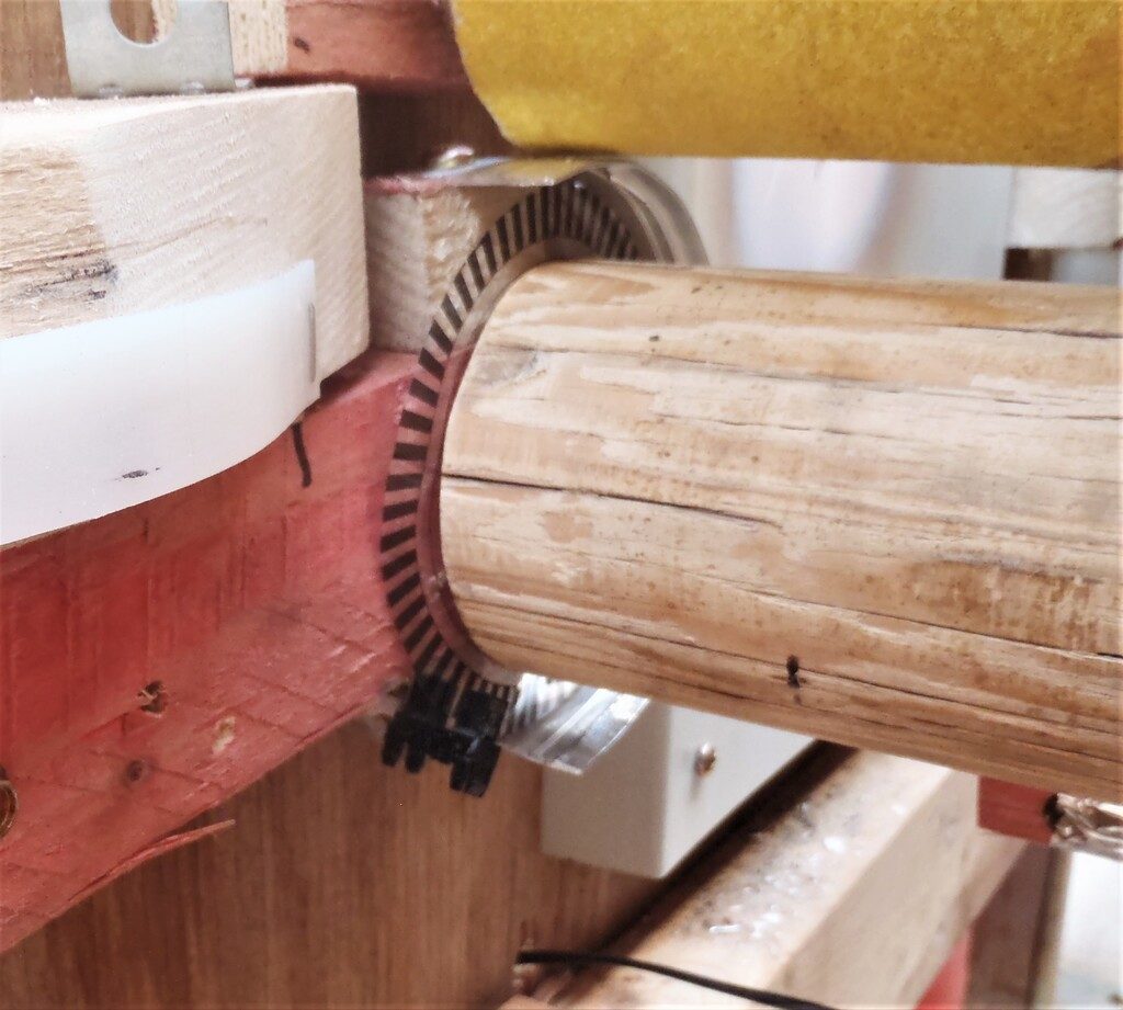
Encoder-disk-and-sensor-on-a-pinch-roller
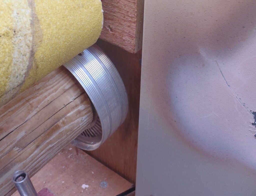
Protecting-the-plastic-encoder-from-the-heat
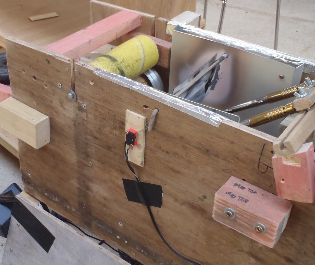
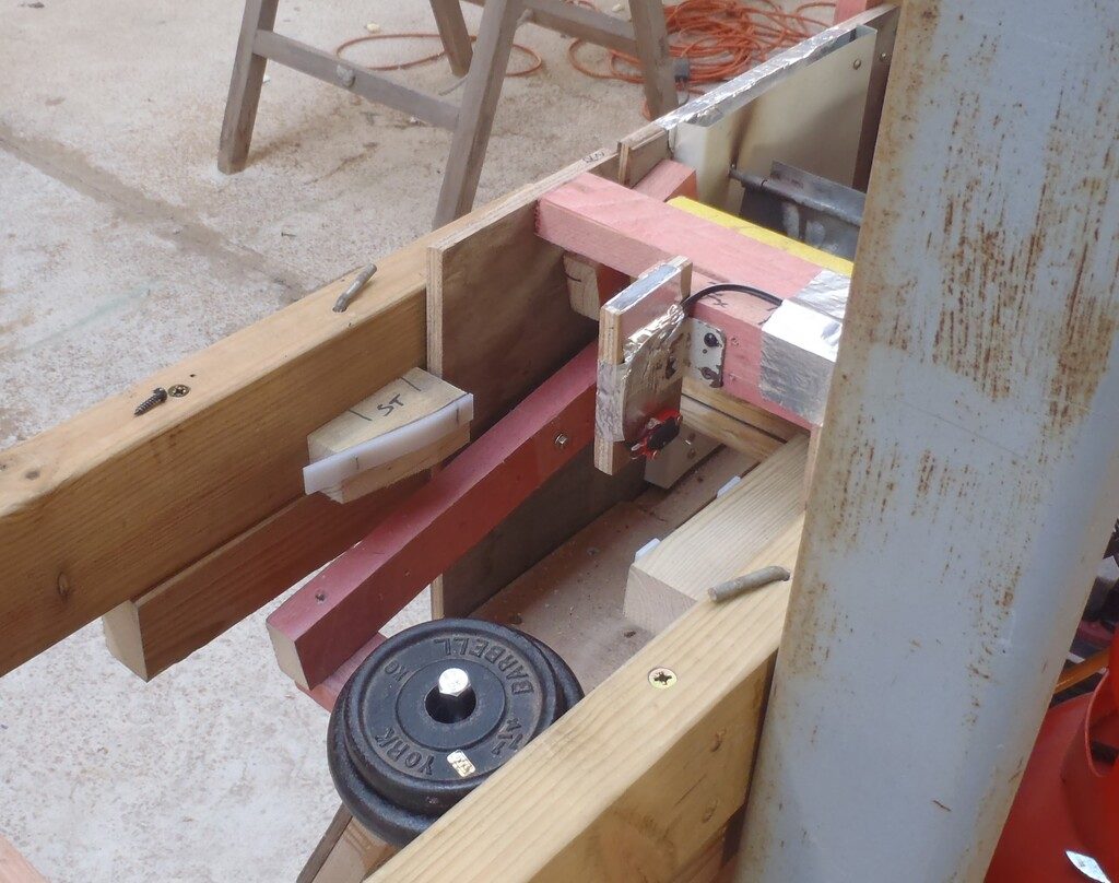
The next problem was that when we turned on the burners the output switch got too hot! Again a different system was needed, we needed to get the switch away from the heat so various pivoted arms where fabricated, tried and modified. But after a long time trying to get them to work reliably we gave up on this idea as well.
Wheel-lever-output-switch
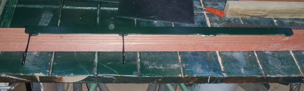
A non contact sensor was needed and a light sensor placed just below the plank would give different readings to show when the plank was present or not. This was fabricated and fitted and worked! We finally had a working machine and just a bit of fine tuning of the software was done. On the last Saturday a revelation was had! in that there had always been a lever to activate a switch built in to the machine from the beginning. The output flame guard was hinged on a rod which come out the side of the machine and this rod was turned when the flame guard was pushed up by the plank. This rod happened to have a bent end which was ideal for pushing a switch so we fitted a switch so now we have two output sensors which work…
Optical-output-plank-sensor

Output-switch-using-the-flame-flap
So we finally have a machine for processing the planks, which will probably only take a week!

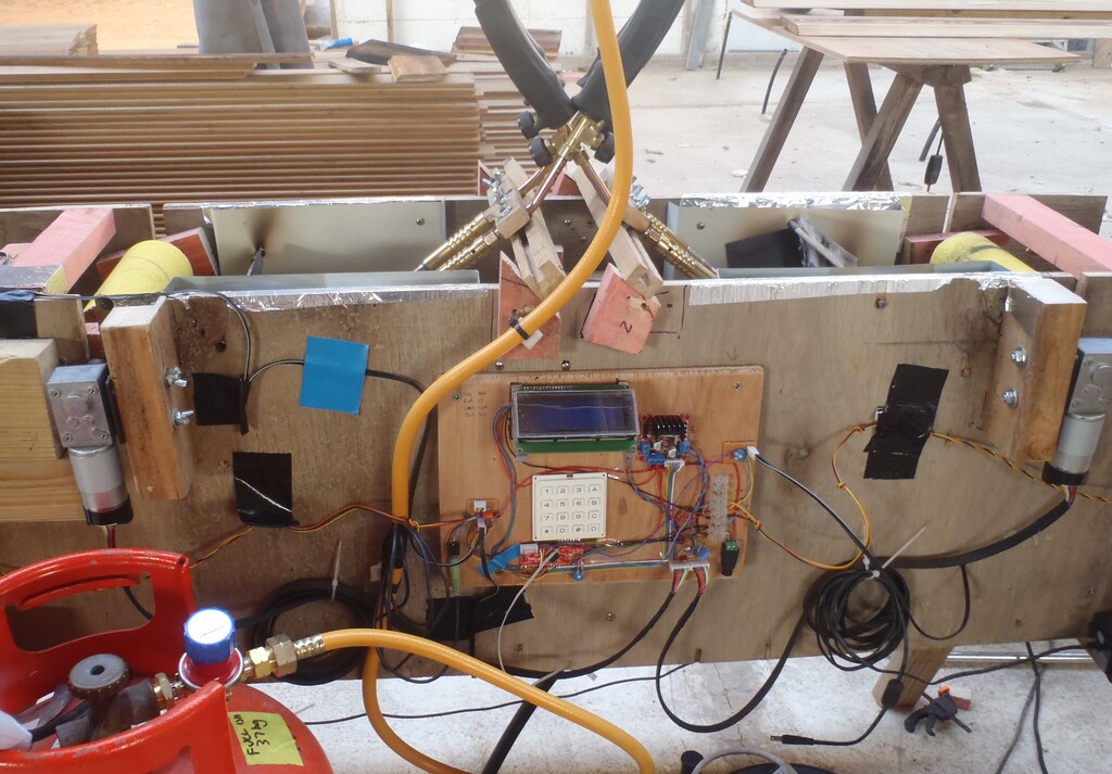
Final-Control-board-and-wiring