Category: Equipment and Tools

The Tools we are using on this Project

  • Planer Machine Has Been Extended

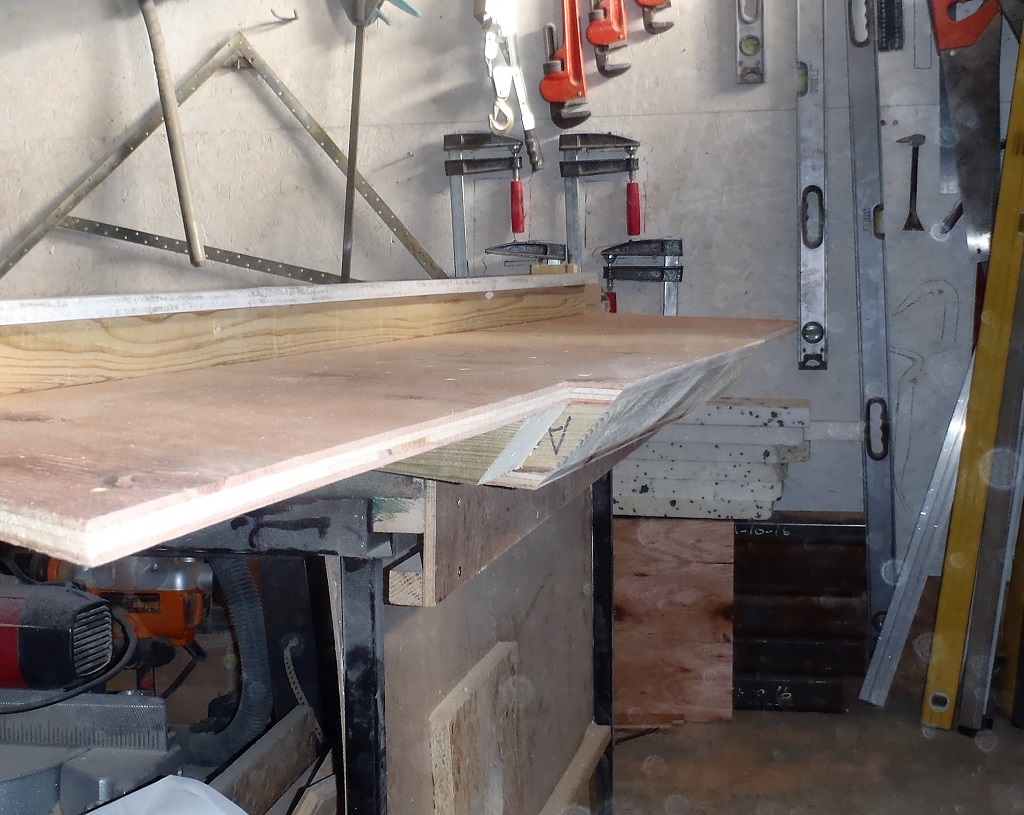
    Today we finished off the task of building two extension tables for our Planer Machine. On Saturday, we had our double thickness OSB boards all set from the gluing and it was sliced down to required size. Then a clearance hole was made in one of these OSB platform for the large knob sticking out the end of the metal table platform (this knob adjusts the depth of cut the planer does) and also we made four wooden legs with an extra plastic cabinet adjustable foot fitted and glued up inside the end of each leg. Today, we mounted these legs to each extension table, bolted on two metal arms and assembled the table to the end of the planer. While we were adjusting the height and level of the new extended table, using our 6 foot spirit level, we noticed that the wooden surface wasn’t quite flat and had a bulge here and there. So we spent the next hour or so sanding the high ridges until it was all flat all over. We did the same with the second extension platform and then proceeded to set each one into place, using glue and screws to fix the wooden bases to the metal arms (plus using several clamps to hold it together while the glue dries).

    Planer-Extension-Table-made

    Planer-Extension-Table-made


    We now have a 3.4metres (11feet) long platform (1.7 metres, a bit over 5½ feet, on each side of the planer blades) and this will, We Hope, Fingers Crossed(!!), bring a much better and more consistent results of achieving a straight and flat edges and surfaces on our Oak Timber!! Tomorrow will reveal all! Grin!

  • Planer Machine Grows Longer!

    Today, we settled down to analyse the planer machine to learn what is happening when we try to plane larger pieces of Oak timber and why it is coming out with a slight dip in the middle. We wondered whether the heavier pieces was causing a slight ‘bending’ of the metal platforms that guides the timber in and out of the machine but carefully putting a series dumbbell weights and watching the surface against a steel rule (using a bright LED torch to shine through any gaps opening up) but nothing happened even after we put 17½ kg load on the very end of the table. The machine has 500mm long input and output tables and reading more about these types of machines on the web, we were concluding that the long pieces of timber is too long for the machine. The cylindrical rollers don’t give enough support because they only hold up at one point and as soon as the timber slide pass, it loses support and ‘moves’ which is part of the problem.
    This means we needed to extend the flat tables to provide a much longer surface to keep the timber on the straight and narrow and the planer then can do it job on removing the excess material that is causing the bow or dip.
    So this afternoon, we created two thick wooden platform made from two layers of 18mm OSB board, measuring 300mm wide by a metre long and these were sanded smooth and then glued together. Next we got out of our metal supply two lengths of 50mm wide by 3mm thick steel strips, both being more than 2metres long. These were cut to form four 1metre pieces. Then a triple set of 8mm holes were drilled in both the steel strips and also into the sides of the metal (aluminium) tables. Finally, we drilled a series of 5mm holes down the other end which will allow us to screw our thick wooden platform pieces into place. We will slightly enlarge the steel holes (the set of three holes) so we can wiggle up and down the whole extended platform so it becomes dead level and aligned up with the rest of the machine. Finally, we will put on two legs underneath to help support these extended guides as the whole machine will suffer and tilt over when it tries to handle heavy and long Oak timber pieces.
    This is taking quite a while to analyse, design and implement this necessary modification to our planer machine but we want something that will be solid and long lasting so we can deal with all our Oak timber for the whole building project. So just a couple of days of work here will save many, many days of frustration and problems later on!

  • Top of Walls Slicing Jig

    After lunch, we thought it would be a good idea to make another template jig to help with the task of slicing off the tops off the cement boards of the walls that protrudes up between all the rafters around the building.

    Top-wall-trimming-Jig

    Top-wall-trimming-Jig

    Top-of-wall-trimmed

    Top-of-wall-trimmed


    The router machine is guided between the two lines of the plywood support and the cutter is positioned just so it can move and slice off the cement boards at just the right angle and flush to the height of the rafters (as you can see in the photos above).
    Shaun can go around doing this job while Stephen is doing analysis work on our Oak Timber. Yes multi-tasking!

  • Bevel Slicing Machine Is Completed

    This morning, we concluded the creation of the new Bevel Slicing machine with the addition of of a G-clamp to anchor the required angle for the bevel.
    Then we created a much simpler guide template that fits over the end of a rafter and provide both a starting platform to rest the saw machine and then another platform on the other side to receive the saw machine as it comes through the cut to arrive safely without falling off or anything like that.

    Bevel-Saw-1

    Bevel-Saw-1

    Bevel-Saw-2

    Bevel-Saw-2


    The guide rail (a flat 89mm CLS timber) has an extra thin strip of wood to make sure that the saw machine on its sled won’t tip upwards.

    Angled-guide-for-bevel-saw

    Angled-guide-for-bevel-saw

    Bevel-saw-on-guide

    Bevel-saw-on-guide

    Sawn-Bevel

    Sawn-Bevel


    This template is only suitable for 32degrees angled ends and orientated to the left direction. We will have to adjust or make another template to do the right handed orientation, until we have finished all the rafters that has the 32degrees ends on them.

  • Bevel Slicing Machine Designed and Nearly Finished!

    Today, we turned to making a new tool to help us slice angled ends to a certain number of our rafters that needs to fit up against diagonal hip or valley  beams in the roof.

    We took an old portable electric circular saw and cut away the original blade shroud to allow a much larger diameter blade to be fitted. To this reduced metal plate, we mounted a sheet of plywood that is bigger than the new blade (300mm diameter) and then put a half a box over the upper section of the exposed blade to protect us from the spinning teeth!!

    Bevel-cutting-machine-Day-1

    Bevel-cutting-machine-Day-1


    We then put on a double hinge near the bottom of the saw machine and mounted a thick 18mm plywood base which will serve as the sled to run across the surface of the rafter, with an arm sticking out so that it can be fixed down to achieve the desired angle we need when slicing the bevels. We can now get any angles from a minimum of 22 degrees and go all the way up to an impractical angle of about 85 degrees! We only need to get to 60 degrees for our maximum angle!

    The second part of the machine is a template to fit onto a rafter which will provide the support and guide for the sawing unit. We wanted to have the template to flip around from doing a left handed cutting to a right handed cuts without having to unscrew and refit various parts. The design calls for a parallelogram aligned set of bracing arms (to hug the edges of the rafters) and the second set to provide the guide for the saw unit itself.

    But it proved to be very difficult to get everything exactly measured and aligned. We tried several different methods and measuring schemes to position the mounting screws but we couldn’t get it working.
    So tomorrow, we will have a rethink and come up with a much simpler design and just work with the main premise of just needing a straight guide for the saw unit, set for the required angle and also parallel to the end and then clamp or screw it to each rafter in turn. Perhaps have a second one made to do the flipped around cuts. We will see what comes out with a night of sub-conscious thinking!

  • Ripped Up Neighbour’s Hedge!

    After lunch today, we helped out our neighbour by driving our Mini Digger up the Loke and then proceeded to rip and grub out their Hedge fronting the Loke.

    Neighbors-Hedge-grubbed-up

    Neighbors-Hedge-grubbed-up


    It was very rewarding for us, especially for the fact that we haven’t used the mini digger for months and months, but the machine started first time! It took only about 30 minutes to do the job!

  • Vacuum System Construction Continues

    These last two days have seen more work on the new Vacuum System for the workshop. Yesterday saw the electrical wiring, switches and sockets being fitted to the machine module (housing the two motor units). The idea is to have a high current 32Amp lead coming from the utility rail to enter into the box, split into two 13Amps lines. One for the vacuum motors and the other line, via a socket on the back of the unit, going onto to the work table, next to the vacuum pipe.


    A rotating switch (taken from an old fan heater) provides the means to switch one or both motors into action, to provide two levels of vacuum power. This is not exactly correct way to describe this as the level of the vacuum doesn’t change when both motors are running, but what actually happens is, there is a great increase in air flow and this feels as if it has a higher vacuum power. It is more true to say that it is a case of how fast the air moves up through the pipes and the faster the air gets “sucked” up the pipe, the broader the effect of materials being caught and dragged along with the air and disappearing up the pipe!
    One result of all the unit being connected together (the vortex separator chamber and motor unit), is the noise! The motor noise is not so bad and we could reduce the noise with some wadding inside the motor unit, but the loudest noise was coming from the Vortex Separator chamber! It was very loud, like a tornado .. which is what it is!! We probably will build a box around the vortex unit and put more wadding inside to keep some of the noise in – We Hope!
    The last job of the day was to electrically connect the new “second” line to the work table so we can immediately continue to make use of the equipment in and around the table. The final task left to do, is the vacuum 50mm hard plastic pipe that comes across the floor from the box, and redesigning the existing pipework (this providing the connections to various equipment for collecting the saw dust and the like) so everything is joined up and ready to Go Go Go!

  • Final Wheel Is Completed for Scaffolding Tower

    This morning, we finished off the fourth wheel by drilling the holes into the foot plate and bolting the wheel together to the foot. We then shortened down all the fatter metal pipe (this is the support pole that goes up inside the scaffolding leg and bolted down) so we can minimised any extra height we would put on the tower (we are wary of this factor because we need to move the towers around and have to slide underneath any rafters we may have put up), the new length of this pipe is 110mm.
    The fourth foot had its nut plate welded back onto the support pole and the threads were all heavily greased to avoid any further rusting problems!!
    These are now ready to be re-installed back onto the tower when we are ready to put up another completed rafter beam.

  • Scaffolding Tower Has Wheels Fitted To Its Feet!

    While we waited for the rain to stop, we rescued the castor wheels from some old tool object which served in the past to help move around the massive steel I-Beams. They were unbolted and set ready for fixing on the scaffolding feet, which we went out at the point the rain was almost stopped and took the flat metal feet off the scaffolding tower. Then, we unscrewed the fat pipe section off the threaded rod and the flat plate (we really had trouble with the fourth one! It was so badly rusted inside that it took us an hour of bashing, blow torching, oiling and everything else under the sun to get the damn nut to move! Eek!). Then each plate (10mm thick by 180mm square) had four holes drilled into them and had the castor wheel bolted on, we finished only three of the four before we stopped for the day, .

    Casters-for-scafold-tower

    Casters-for-scafold-tower


    Tomorrow or Saturday, we will do the final fourth foot and then put the new feet with wheels back on the scaffolding tower and this will allow us to easily move this second tower around, just like the other one!

  • Vacuum System Almost Done

    Today, while half the work force is away at a meeting, the vacuum system was continued to be created and assembled. The various holes and boxing were created, the motor units mounted and electrically tested, and each module having rubber draught excluder stuck down around all the edges to seal the various chambers.

    Vacuum-System-Nearly-finished-1

    Vacuum-System-Nearly-finished-1

    Vacuum-System-Nearly-finished-2

    Vacuum-System-Nearly-finished-2

    Vacuum-System-Nearly-finished-3

    Vacuum-System-Nearly-finished-3


    The two boxes are now connected together, the vortex and “big” stuff collection box and the motor units and the “small” stuff collection box as you can see in the photo.
    We have hooked one motor up for a real test run and oh wow, what a suck! Grin! We went around the workshop and vacuumed lots of surfaces, large pieces, dust and wood bits and pieces and all was sucked up. Opening up the final “small” stuff collection box to inspect the filters and what was in there, and it revealed very little stuff! Just a few particles blown into the corners and a little bit on the paper filters themselves and that it! Very good indeed!! Excellent Stuff!
    So to finish off this little project, we just need to put in dampening material inside the motor unit chamber to reduce the bouncing noise and put on a lid with switches to control one or both motors, and maybe need to put a box around the vortex module as well to keep the noise down too. We will see!