While half the workforce is disabled, Stephen was busy designing and building several new pieces of equipment and tools to help with various future jobs that will be needed to be done as part of building the rafters and walls.
The tools were created approximately in the following order:
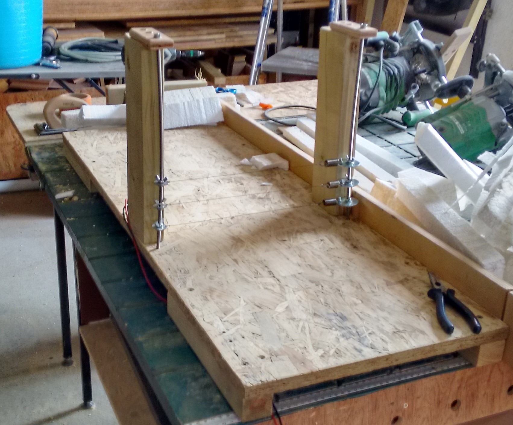
Polystyrene Foam Board Hot Wire Slicer

Insulation-slicing-Triple-hot-wire-cutter
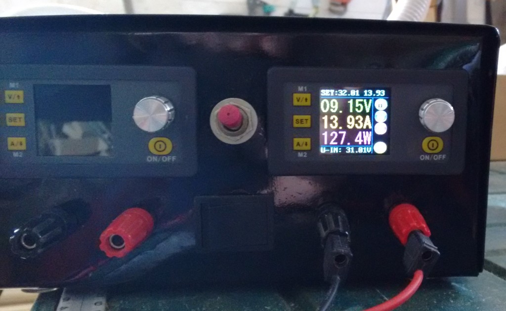
Hot-wire-power-supply
We needed a tool to slice our pile of 8 foot by 4 foot 120 mm thick boards into much thinner sheets (38mm thick) and a few different heights (between 248mm and 265mm). We couldn’t buy the correct thickness of sheet (only 35mm or 40mm) and 120mm thick boards were much less than 3 times the price of the the thinner sheets so we decided to slice the thick sheets down.
Using high resistance wire to form the basis of the machine, we can have 1, 2 or 3 wires, fully adjustable to different heights and separations, and connected to a high powered electrical generator to heat up the wires to melt the polystyrene foam.
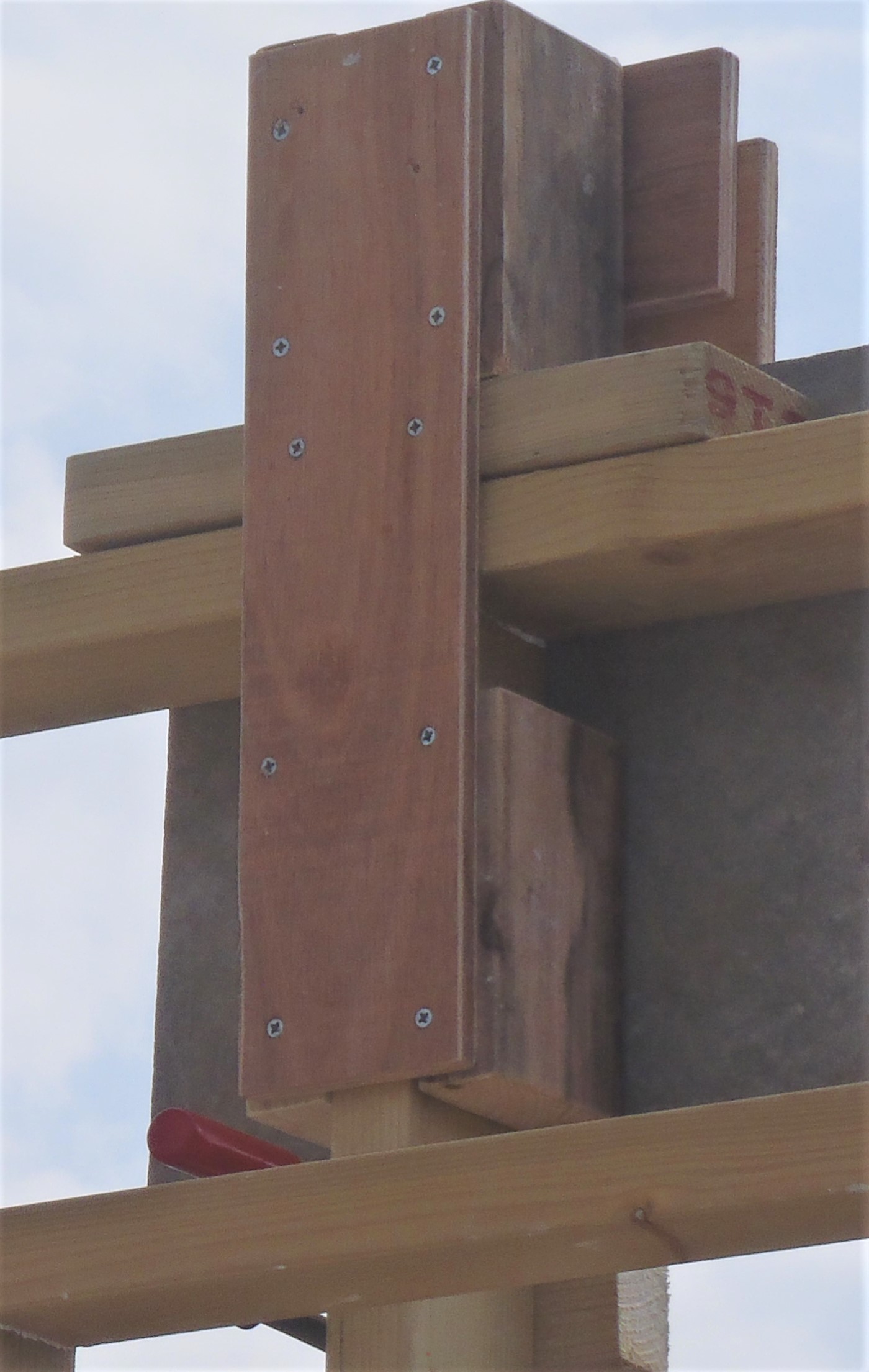
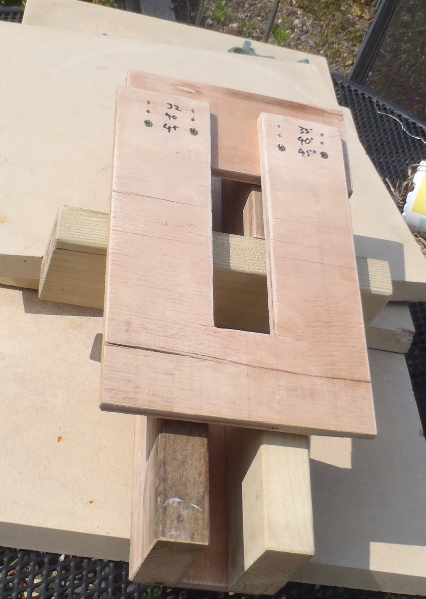
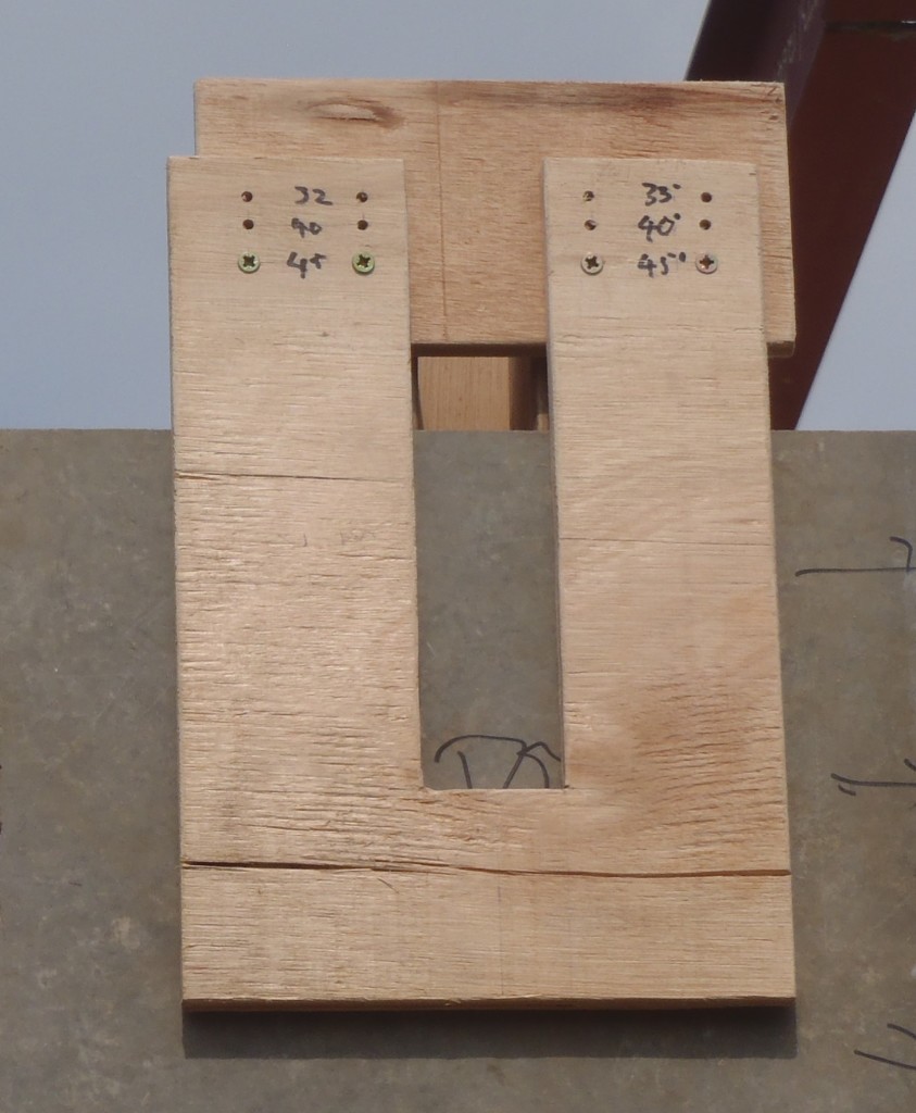
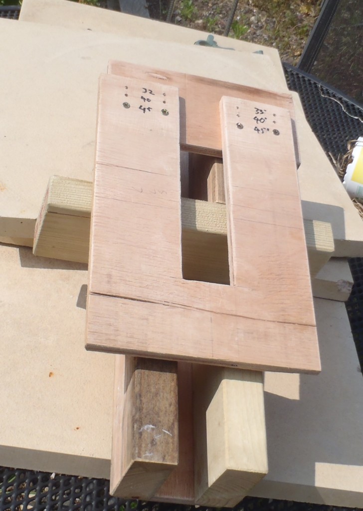
Router Jig to Cut Rafter Slots in Cement Boards
Rafter-end-slot-cutting-template-1

Rafter-end-slot-cutting-template-2
Rafter-end-slot-cutting-template-3
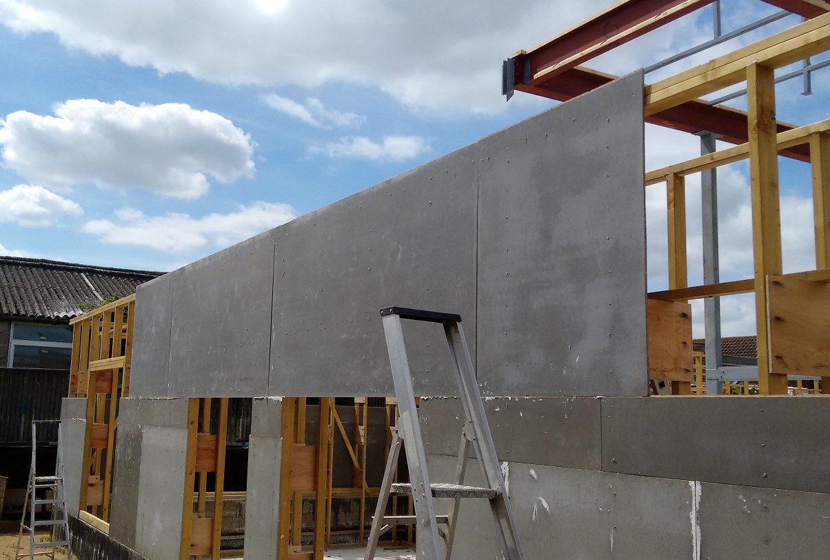
This template slots on top of the wall, at each rafter and leg position, to guide a router to slice out a vertical slot in the wall cement boards. These slots allows the top flange of the rafters to pass through the wall and stick out to form the eaves.
It is adjustable to accommodate the different angles of the rafters.
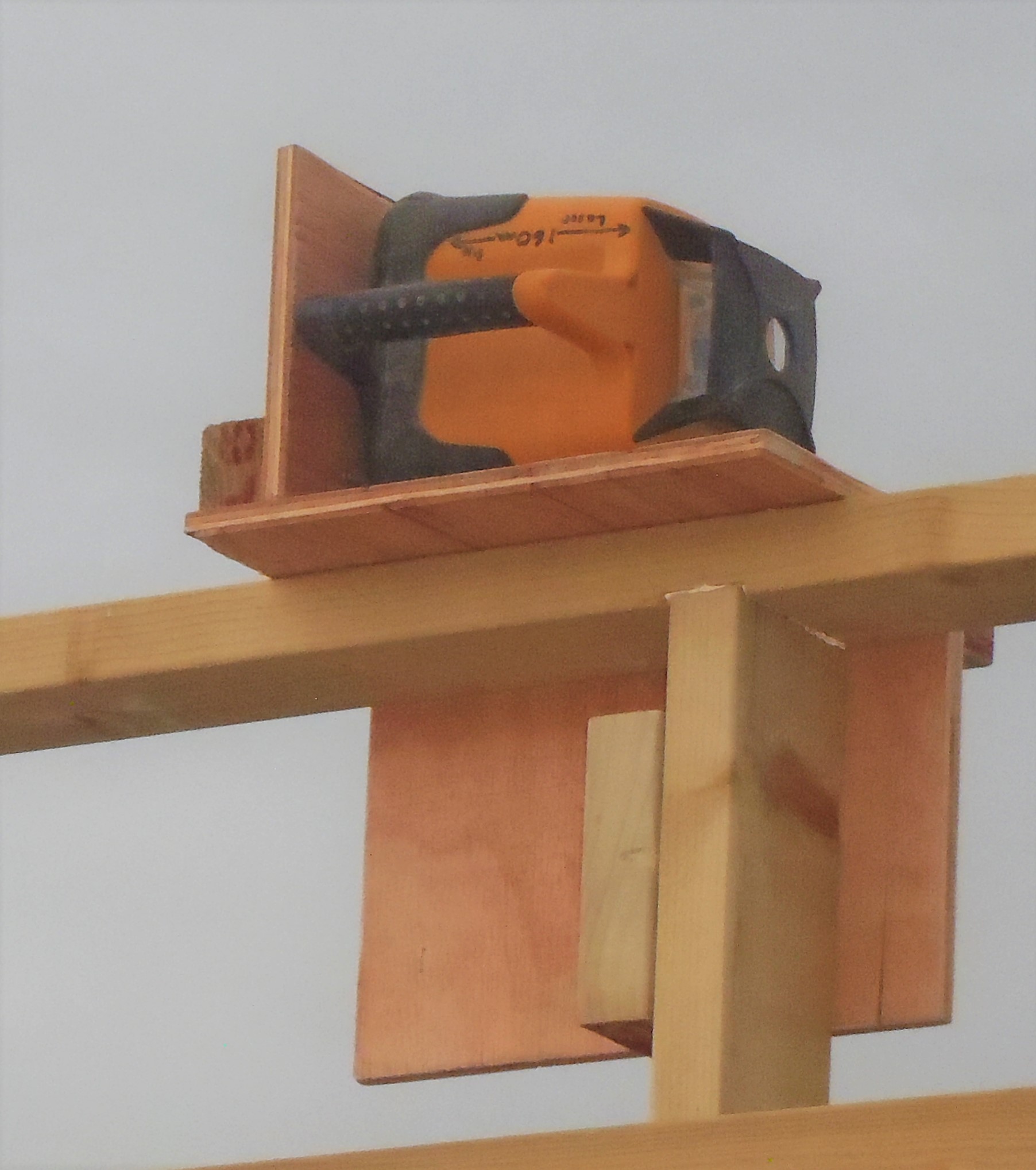
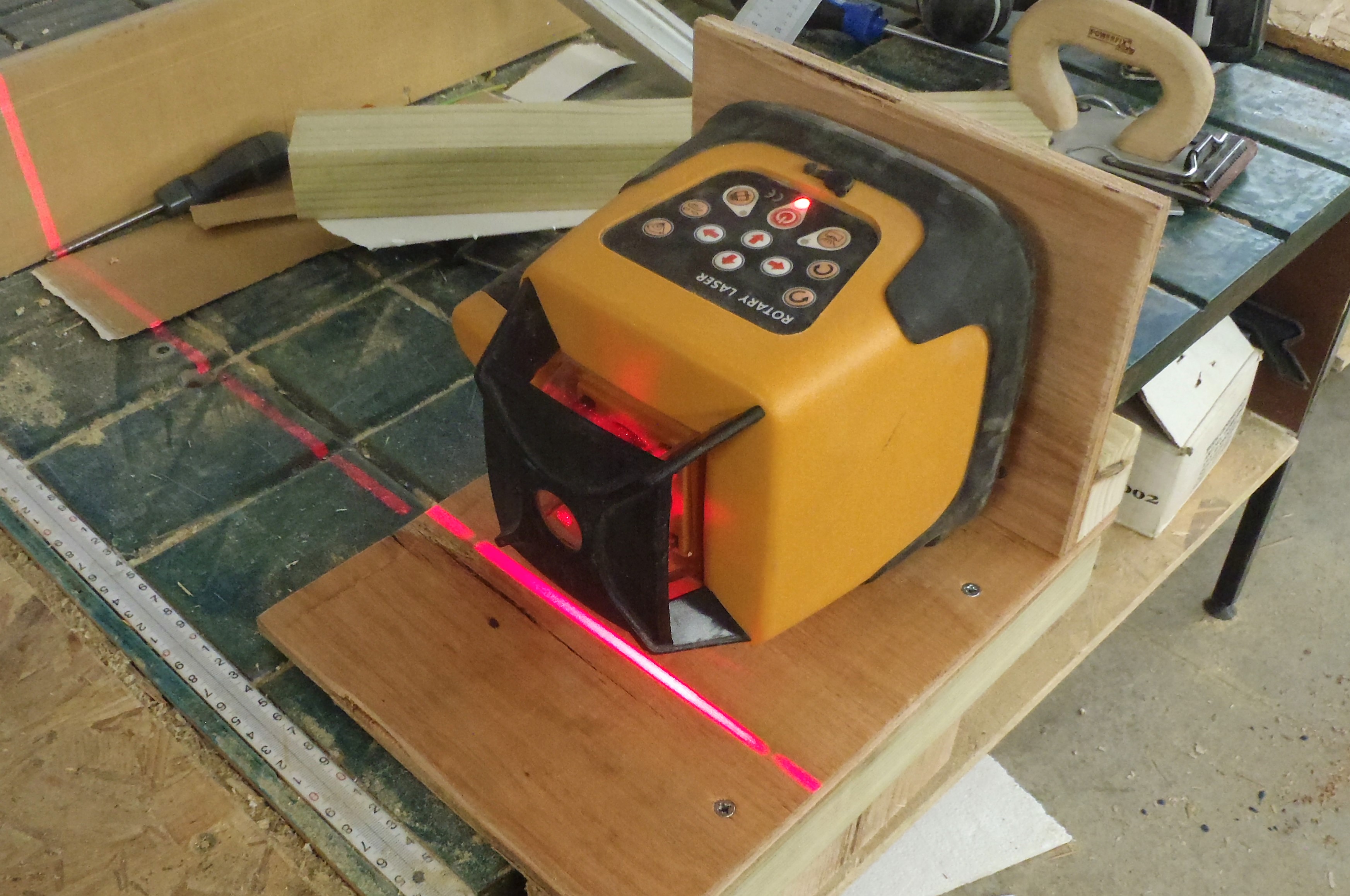
Laser Guide for Wall to Steel Framework Alignment

Laser-Rafter-alignment-jig-1

Laser-Rafter-alignment-jig-2
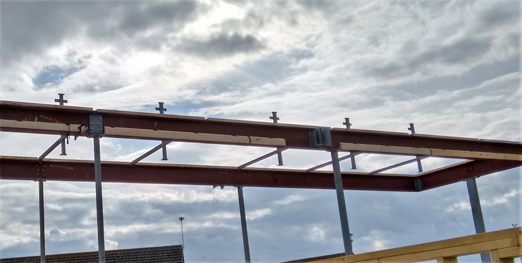
We needed to transfer the position of the Wall Legs where each Rafter sits on, up to the Steel framework so the rafters will be exactly in the correct orientation and be locked into place. The steel framework will have planks of timber glued and screwed against the webbing and flanges of the steel i-beams, but also these timber pieces will have a series of 10mm deep slots sliced in, at the regular 612mm spacing. We need to make sure these slots are perpendicular in relation to the wall legs that the rafter will be joining onto. The laser is aligned to a leg and projects a line at right angles up to the steel beam.
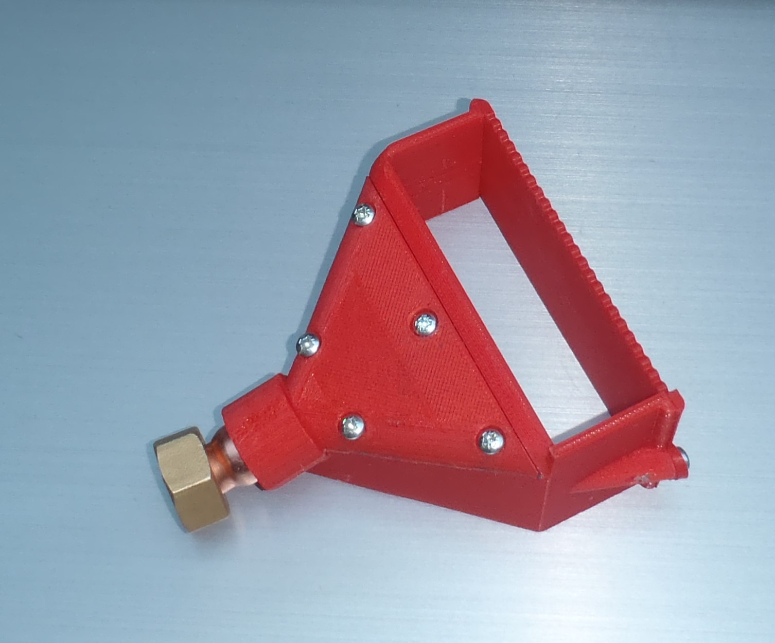
Glue Spreader
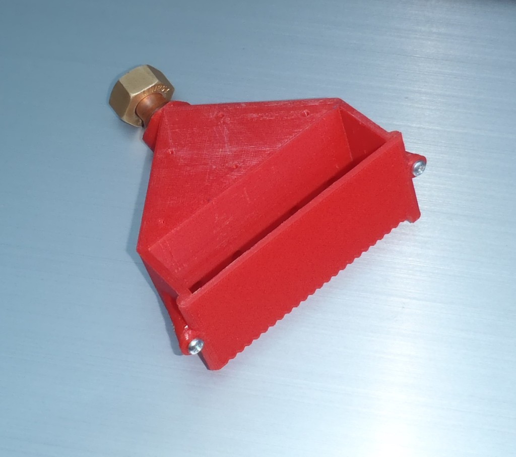
Glue-Spreader-MK1-2

Glue-Spreader-MK1-1
Using our 3D printer, we designed a glue spreader to help us lay down a thin film of the glue on to the timber and stick down other materials like plywood etc. The glue is pumped into a the open space via small tubes, the chamber has a notched side to allow a controlled amount of glue to be spread as the tool is dragged along. The first version was drawn on the computer and then converted into a multi-layered object for the plastic extrusion printer to build, layer by layer, into a solid object.