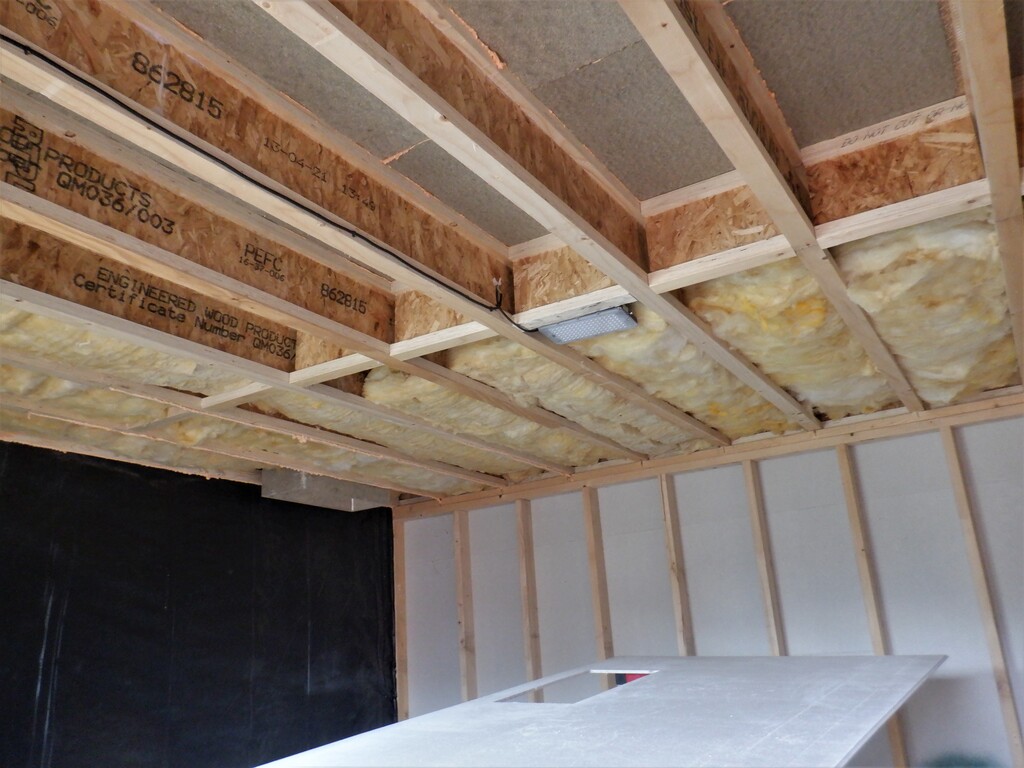
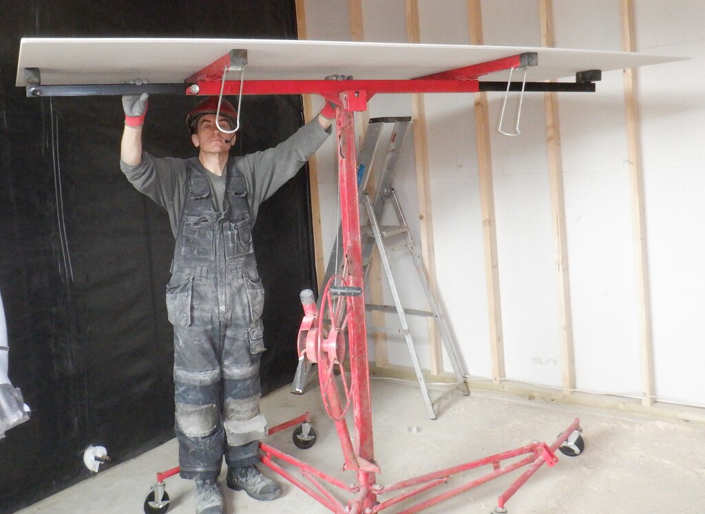
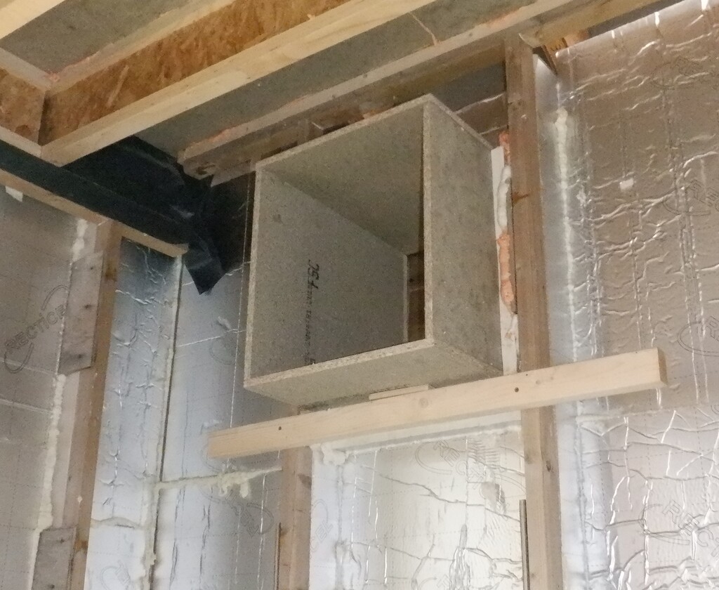
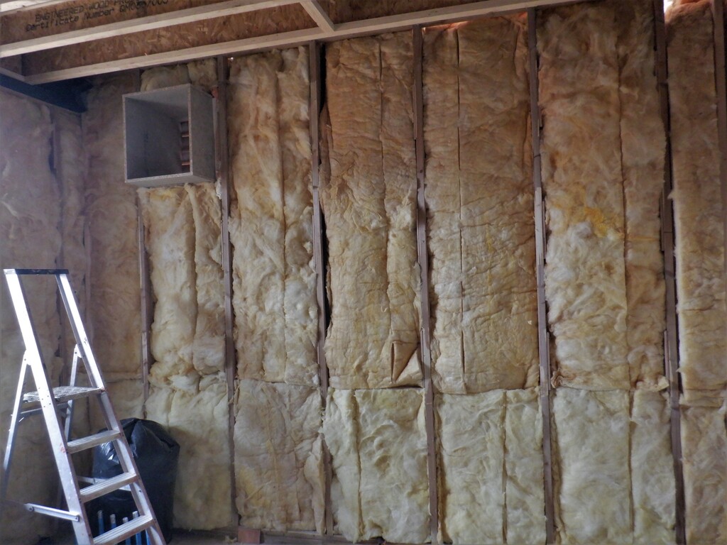
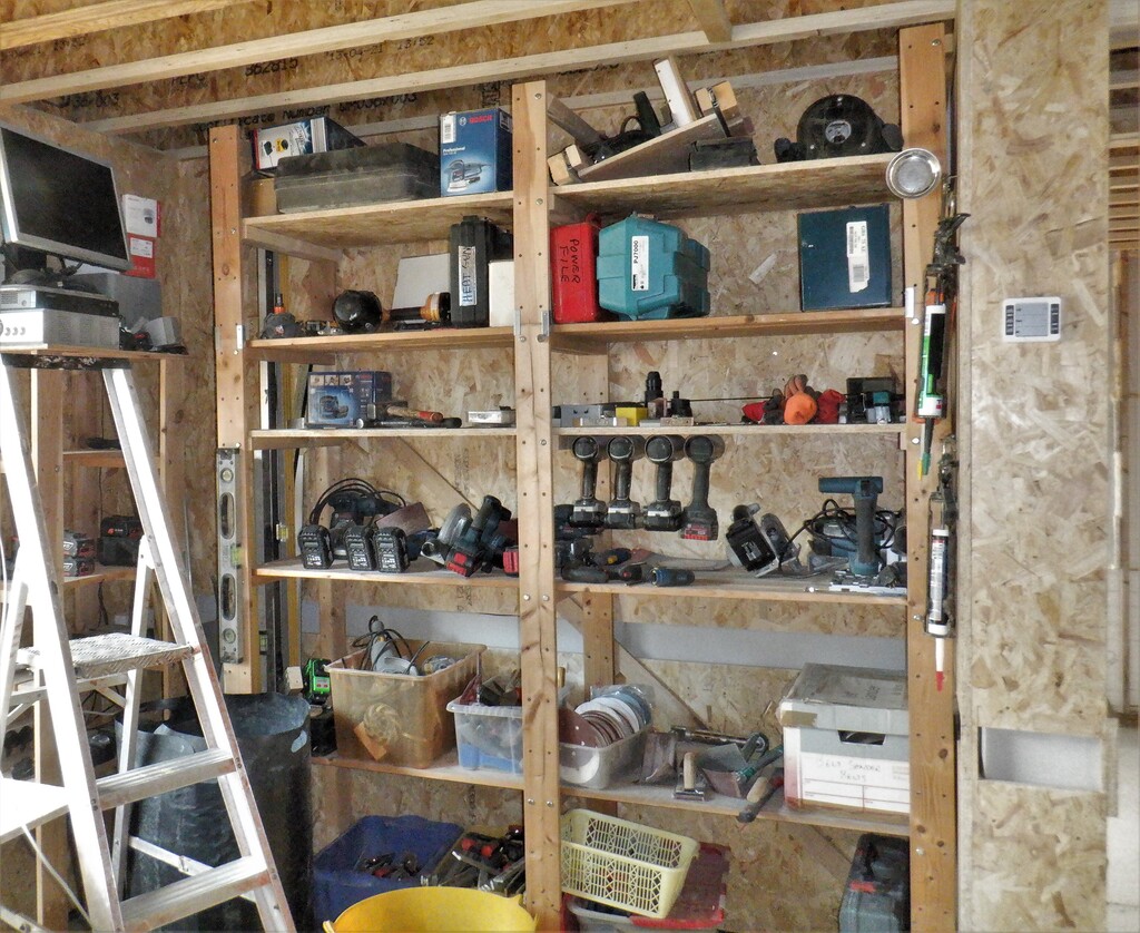
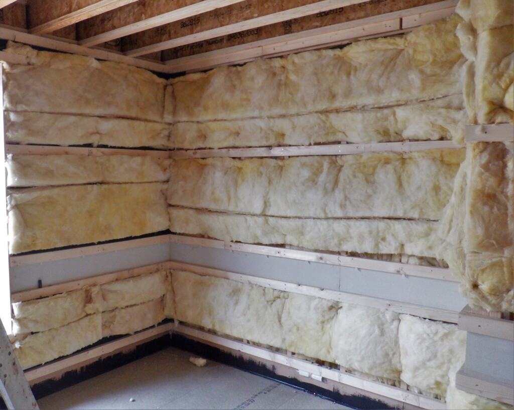
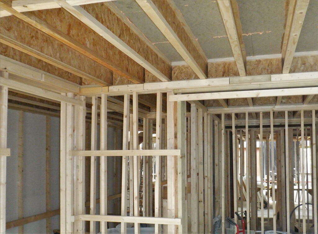
We resumed work on our “Engine Room” within the Utility Room this week by putting on the thick heavy roof to the equipment cupboard. It is three layers of the fermacell boards, making use of left-over pieces where possible especially after we had put on the first layer which was tongue’d and groove’d to stop the edges sagging under the weight. We dug out quite a fair bit of old pieces of fermacell off the rack in the Garage that has been there for years. All to try and improve the sound absorbing qualities of the whole cupboard, to keep any “engine” noises from disturbing the household.
Cupboard-ceiling
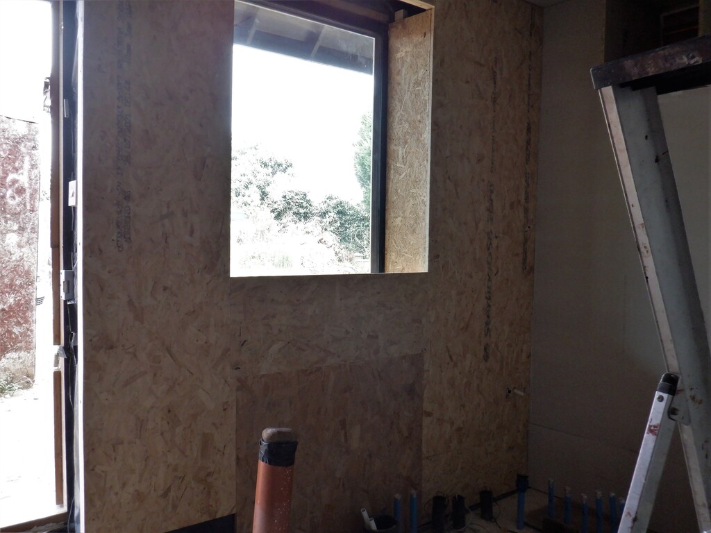
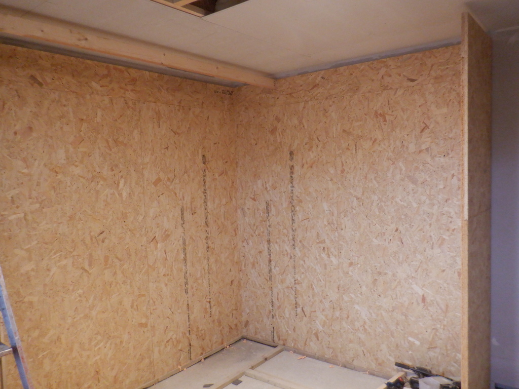
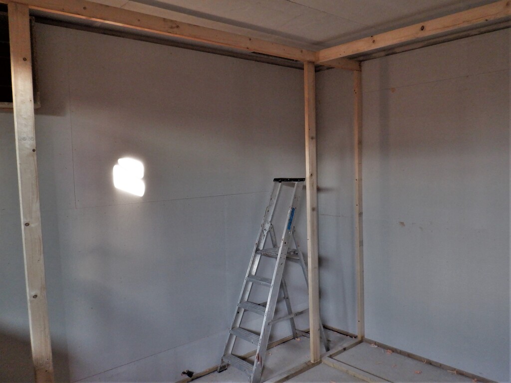
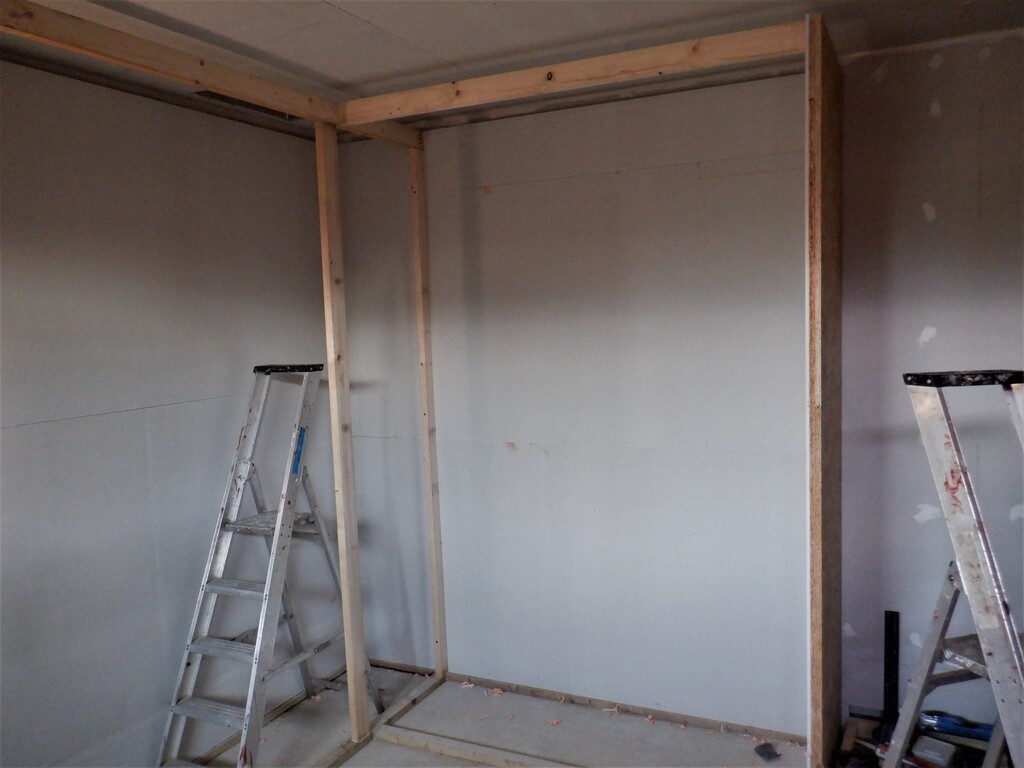
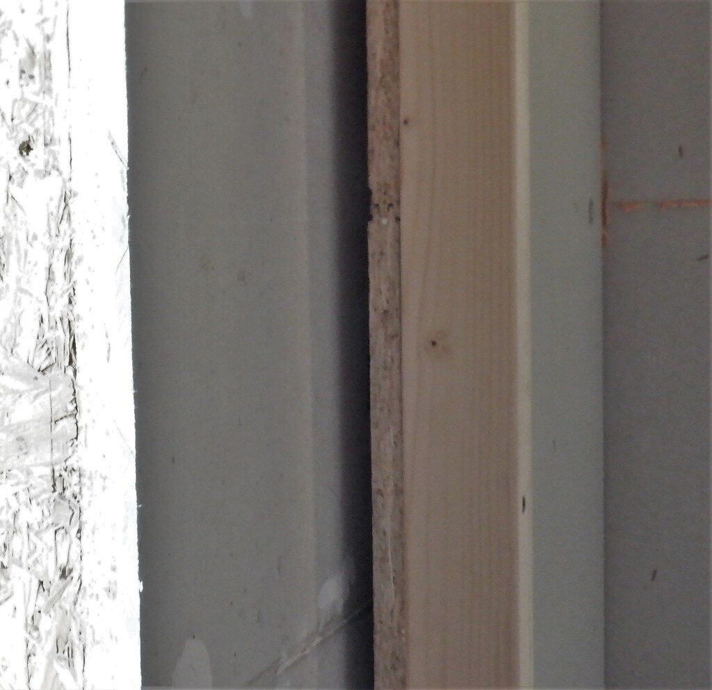
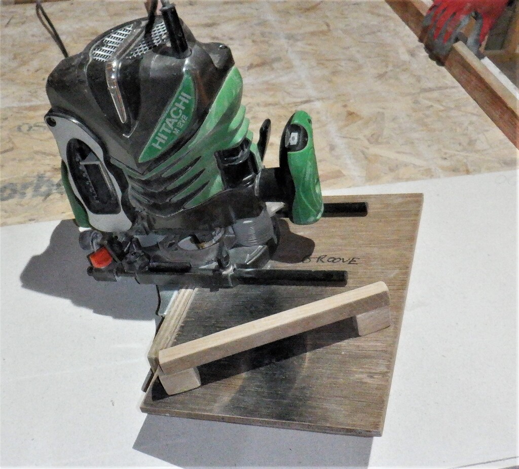
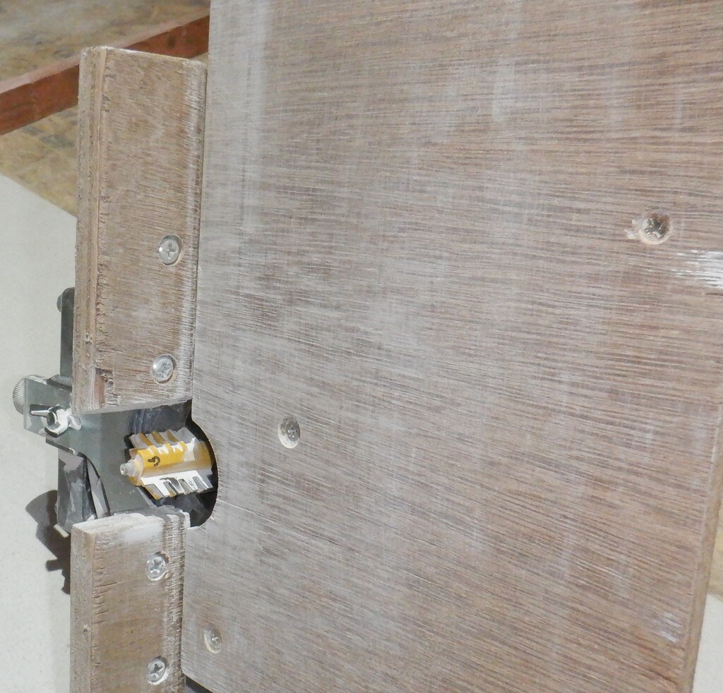
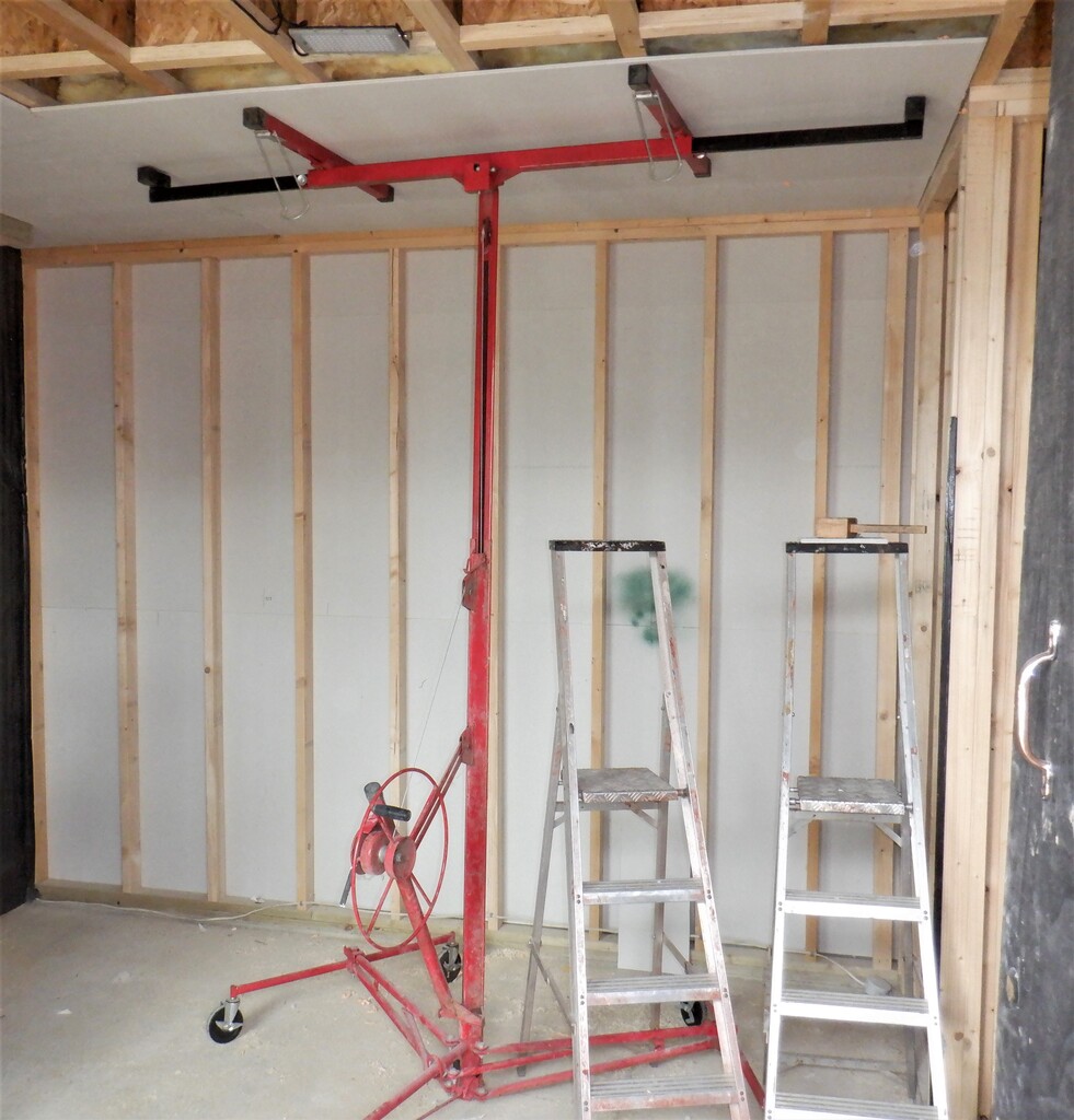
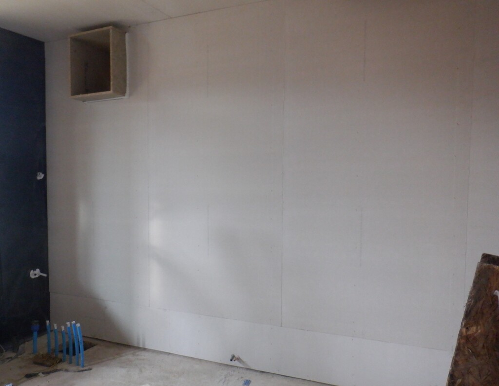
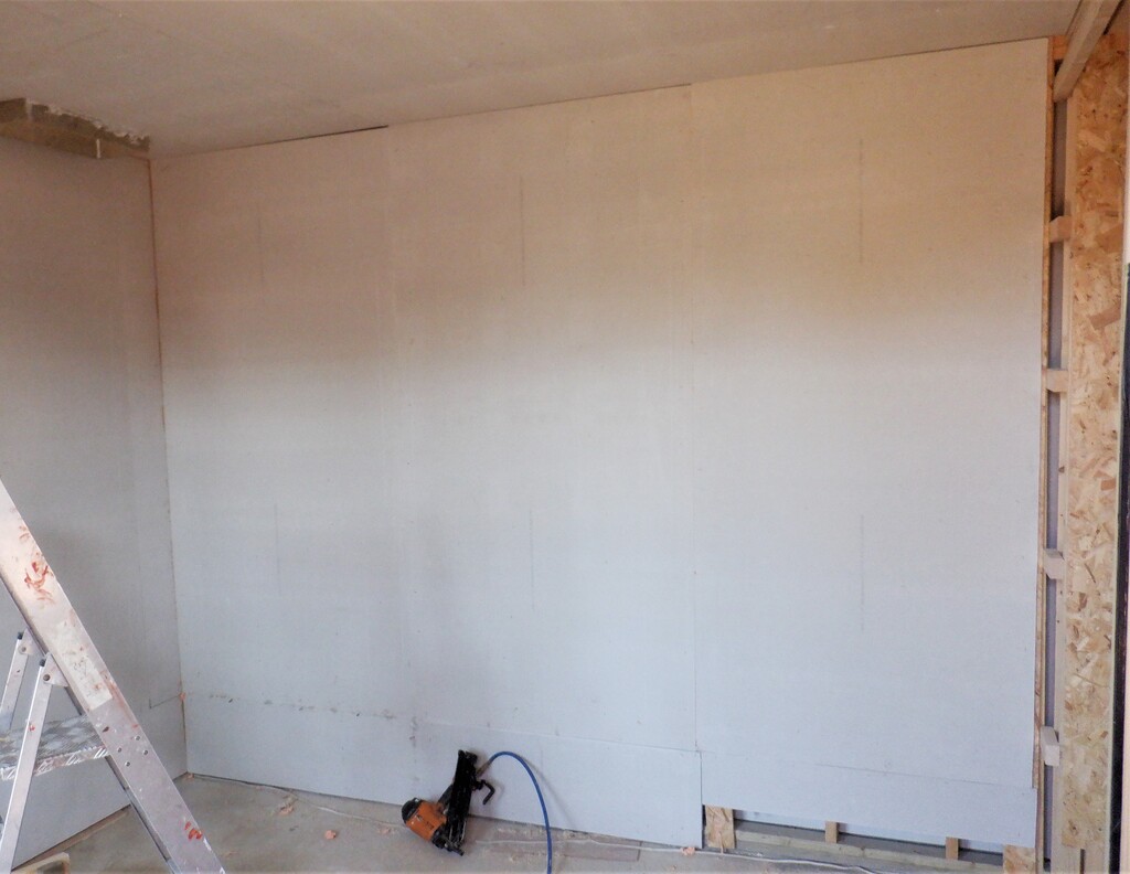
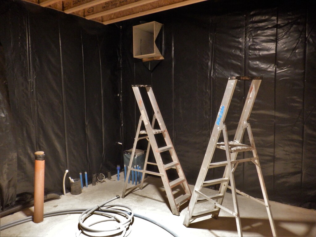
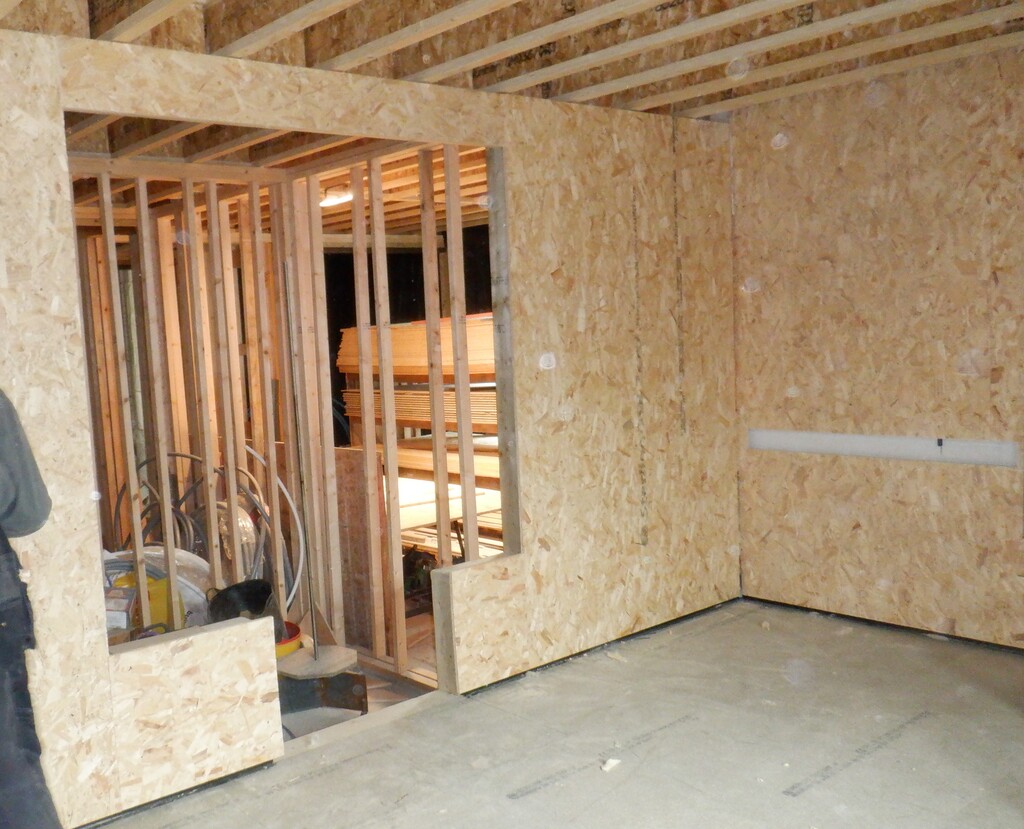
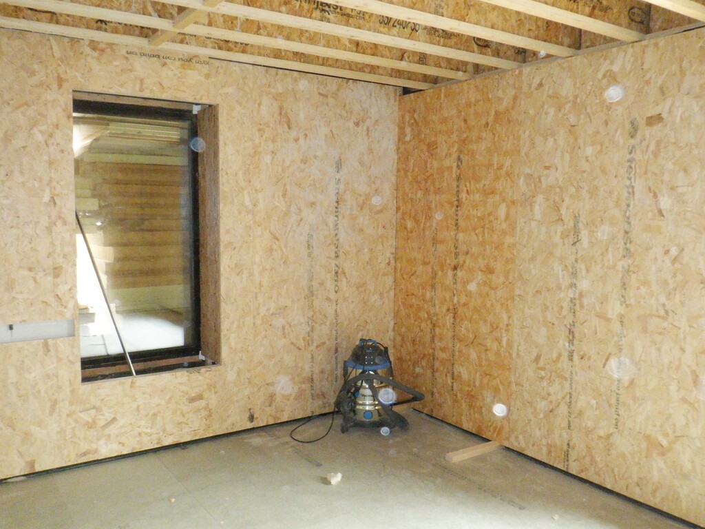
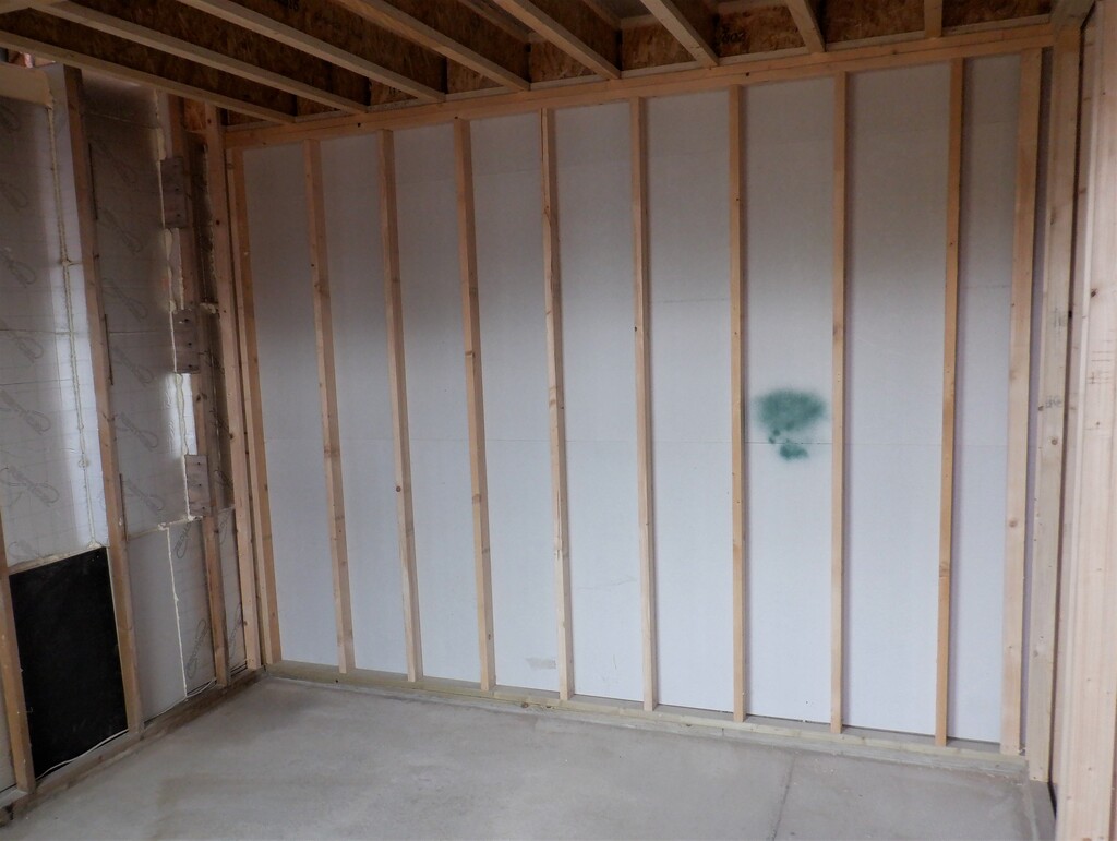
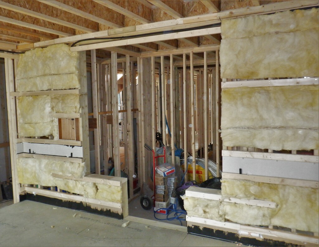
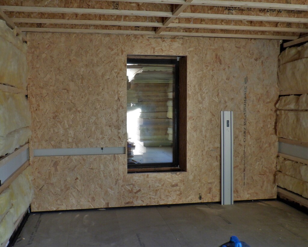
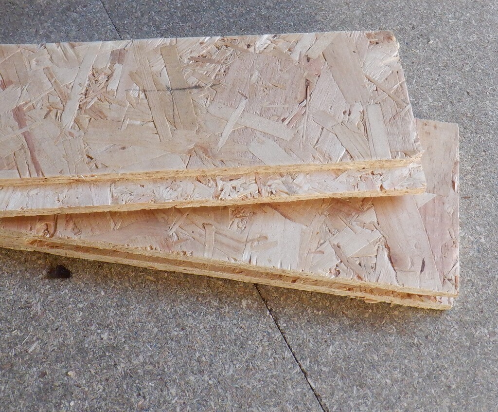
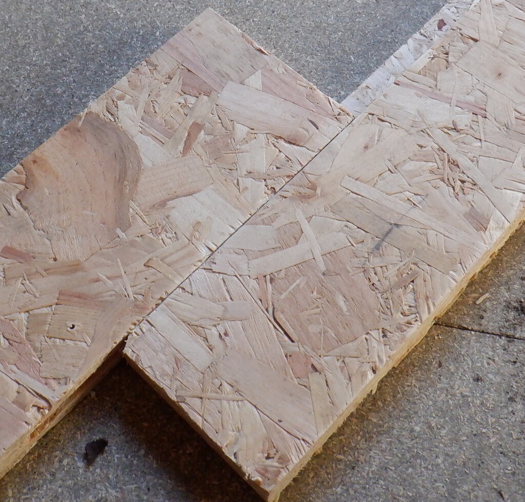
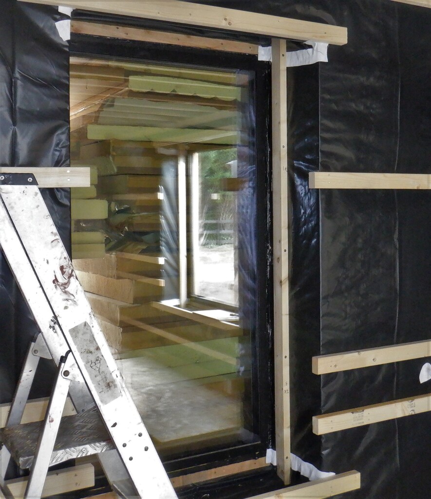
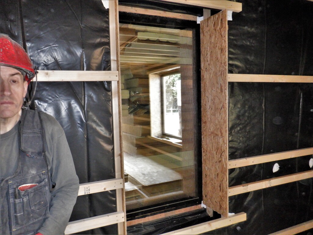
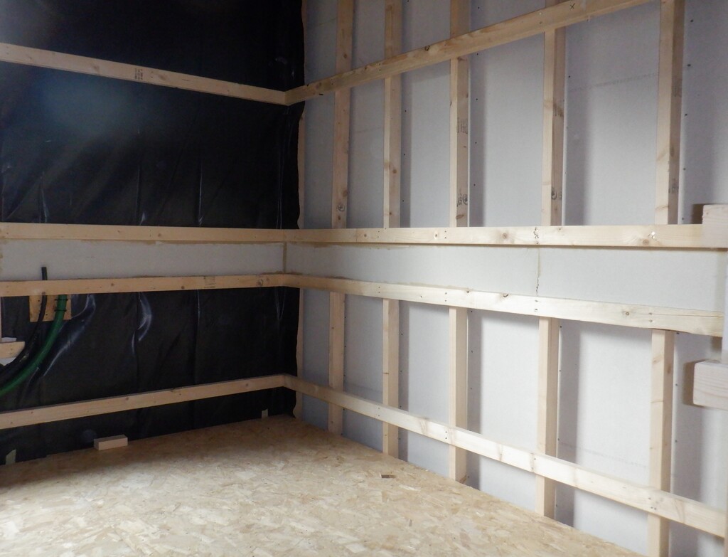
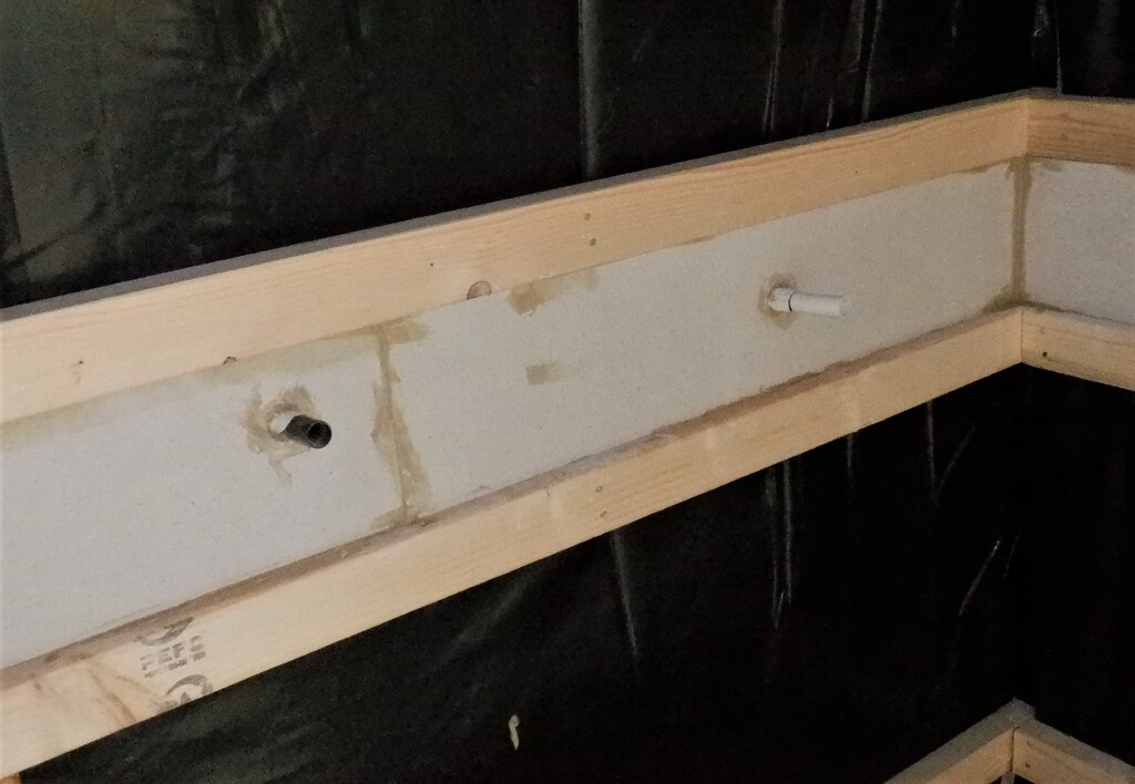
We then built up the front of the cupboard, to continue with this sound proofing technique by putting on two lines of horizontal CLS rails positioned at the floorboard support point and another one higher up at just above the plinth feature that will be constructed around the bottom of the cupboard frontage. We also did the floor support frame for going around the sink worktop zone (under the window) as well. Then, using these two new horizontal rails, we proceeded to insert two layers of OSB 18mm thick boards to squeeze in between the upright posts, to fill in the gap and make a smooth internal surface (we had to insert thin 2mm shims to pad out the two layers of OSB sheets because the posts where 38mm thick and the two layers of OSB only came to 36mm, hence the little thin shims) at which point we went around putting on a layer of fermacell on the inside surface, again for both more sound proofing measures but also to provide a better fire proofing protection too. With all this plasterboard like material now covering all the internal surfaces, we went around filling in all the joints and rounding off the corners with Polyfilla which we then use our new bulk sanding machine that we bought several years ago, just for this purpose. It is connected to our DIY vacuum machine and it was a dream to scrub down the wall, and ceiling, surfaces, removing the excess filler everywhere. All that was left to do by hand were the corners which didn’t take too long to do either.

Cupboard-boarded-at-bottom-1
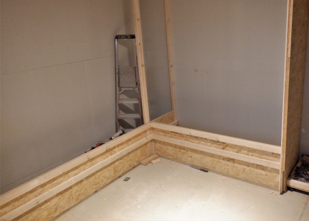
Cupboard-boarded-at-bottom-2
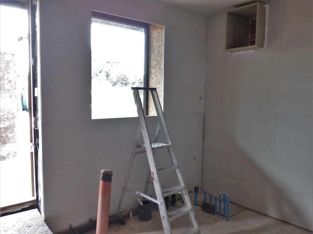
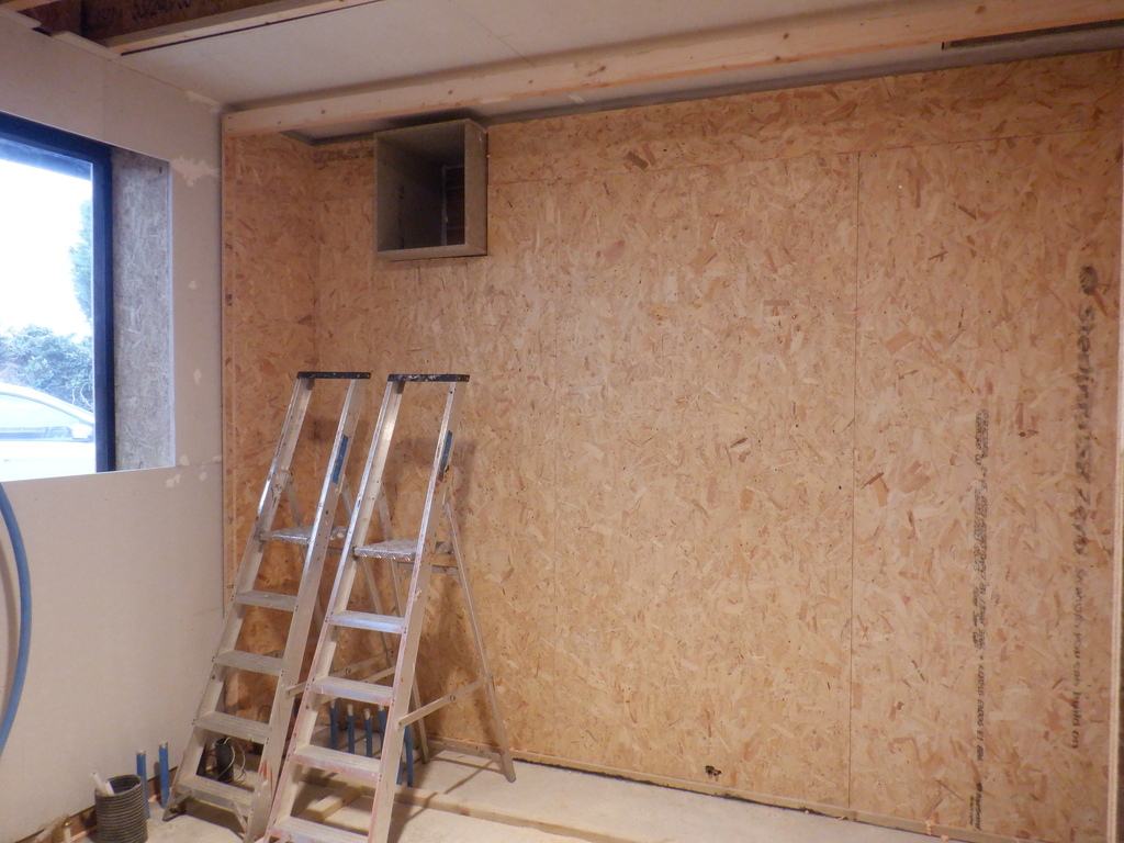
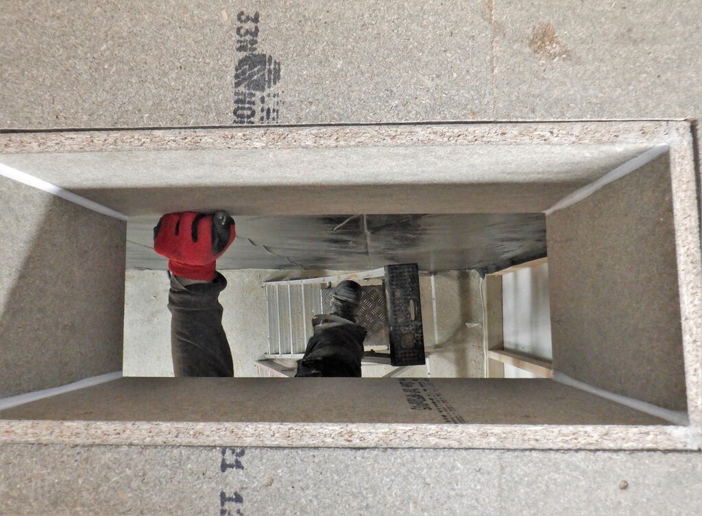
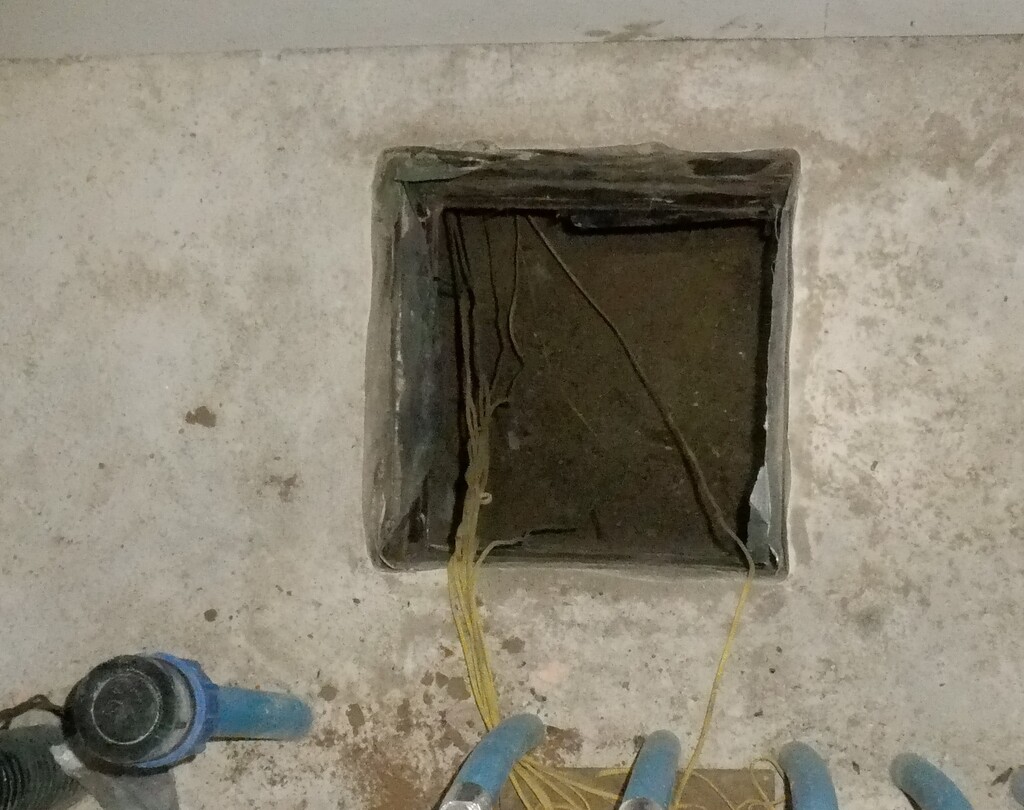
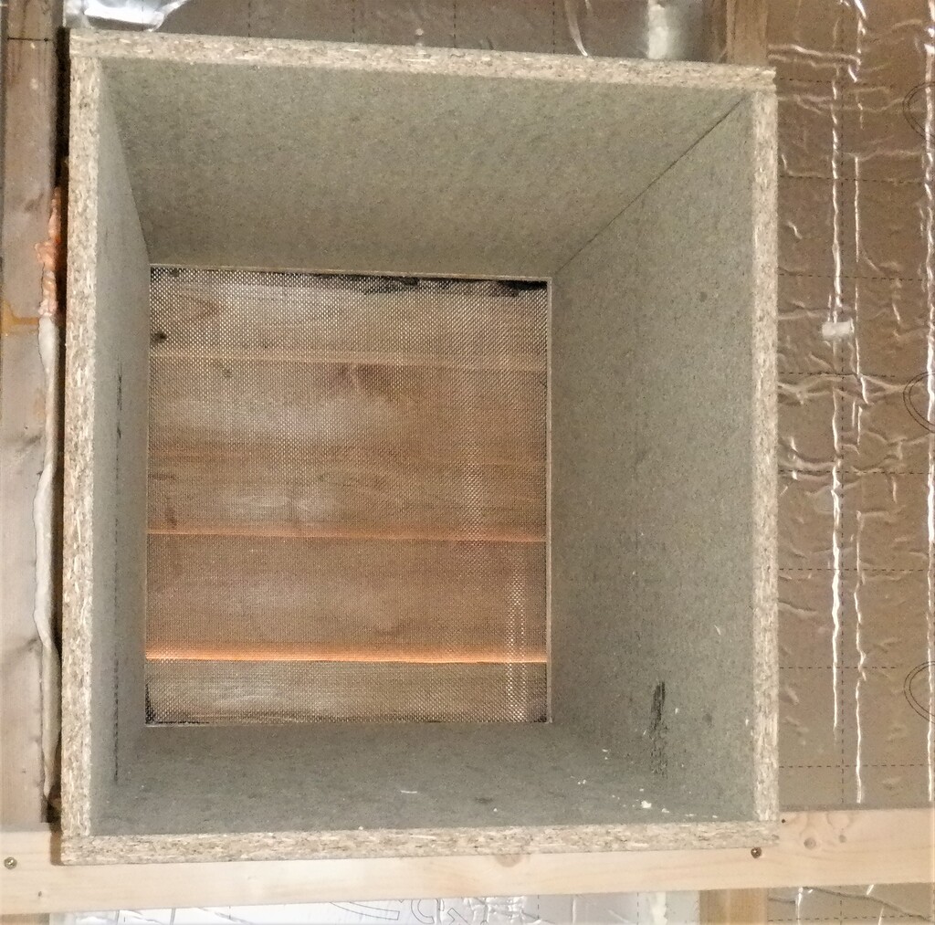
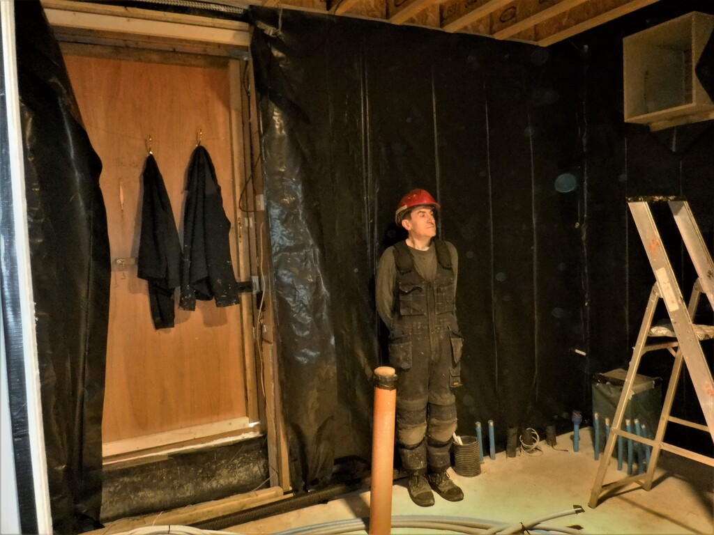
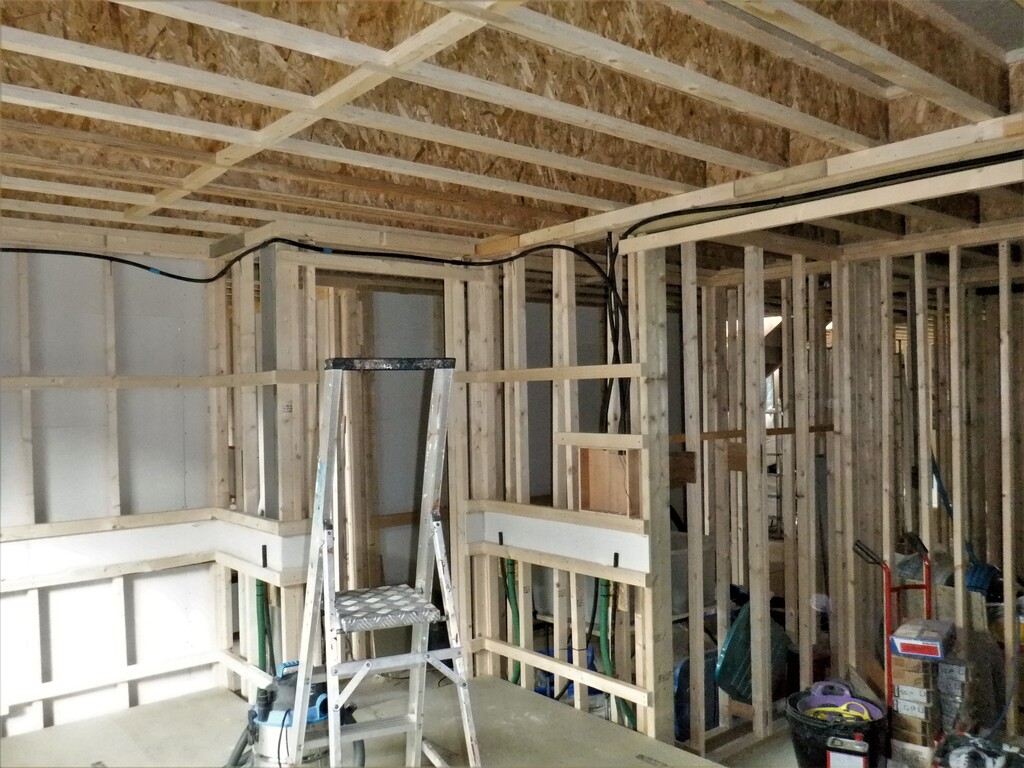
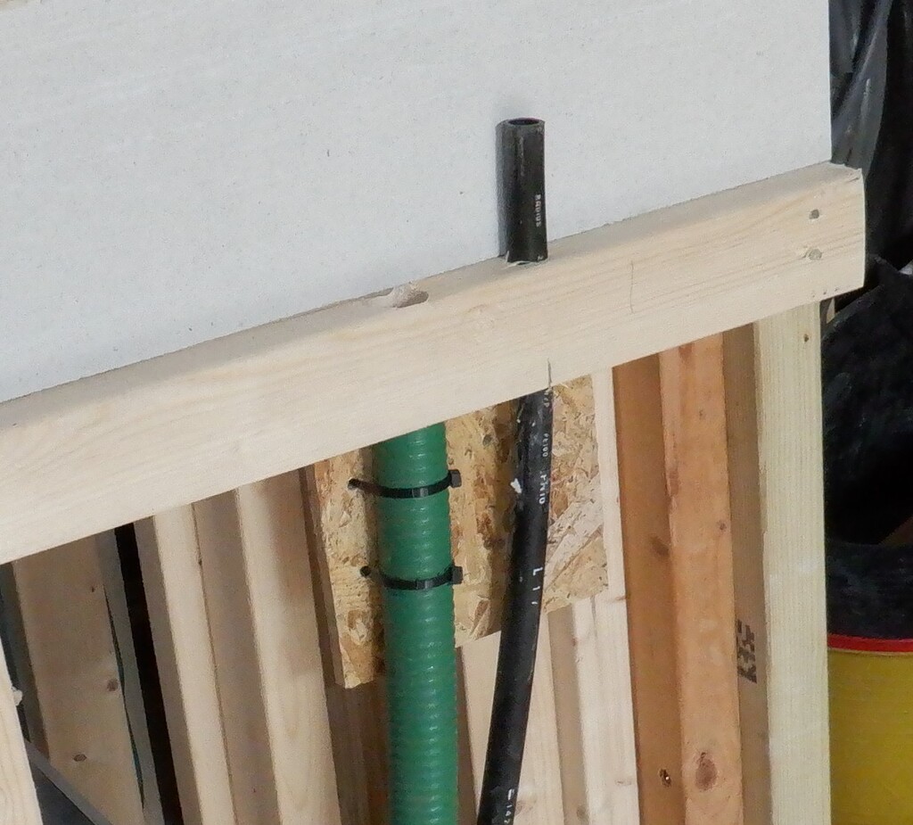
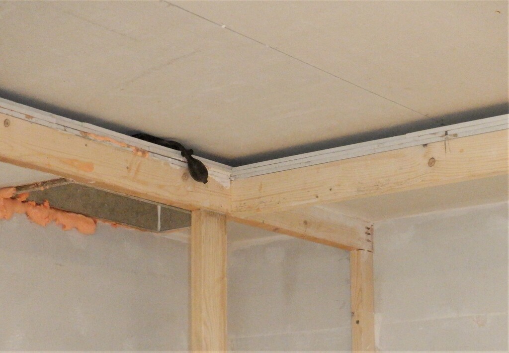
One of the jobs we almost forgot to do was to cut a chimney hole up through our new roof so that we could have our air ducting chute to come down from upstairs. It took a few hours because of the tight close quarters but we managed it and we now have connection for our “waste” air returning from every corner of our house, ready to be refined, processed, recycled and discarded.
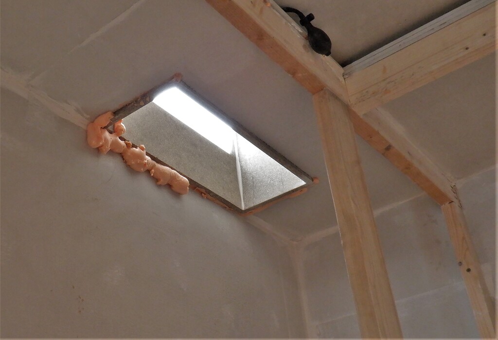
Return-air-duct-through-cupboard-ceiling
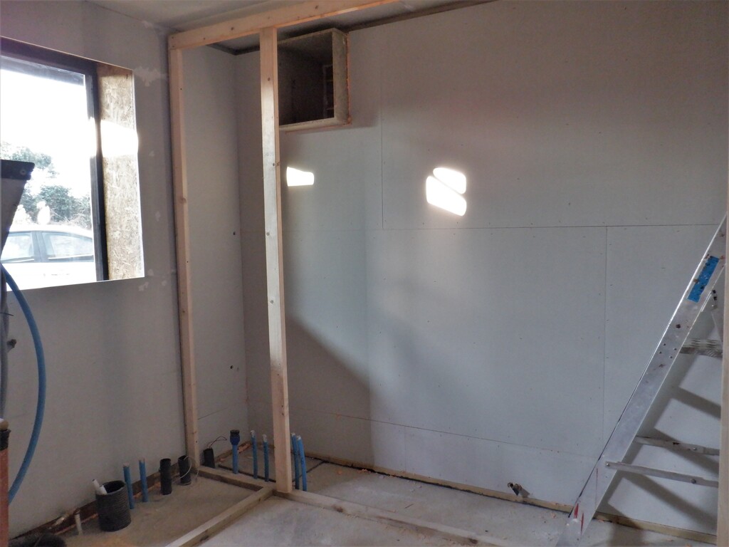
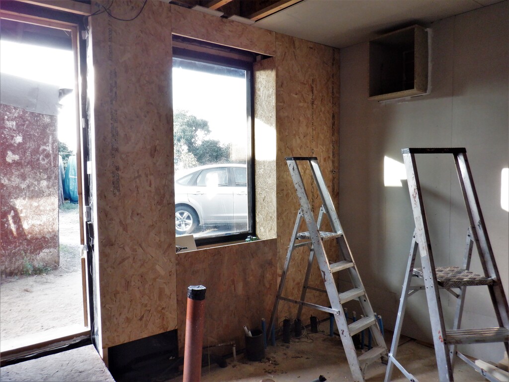
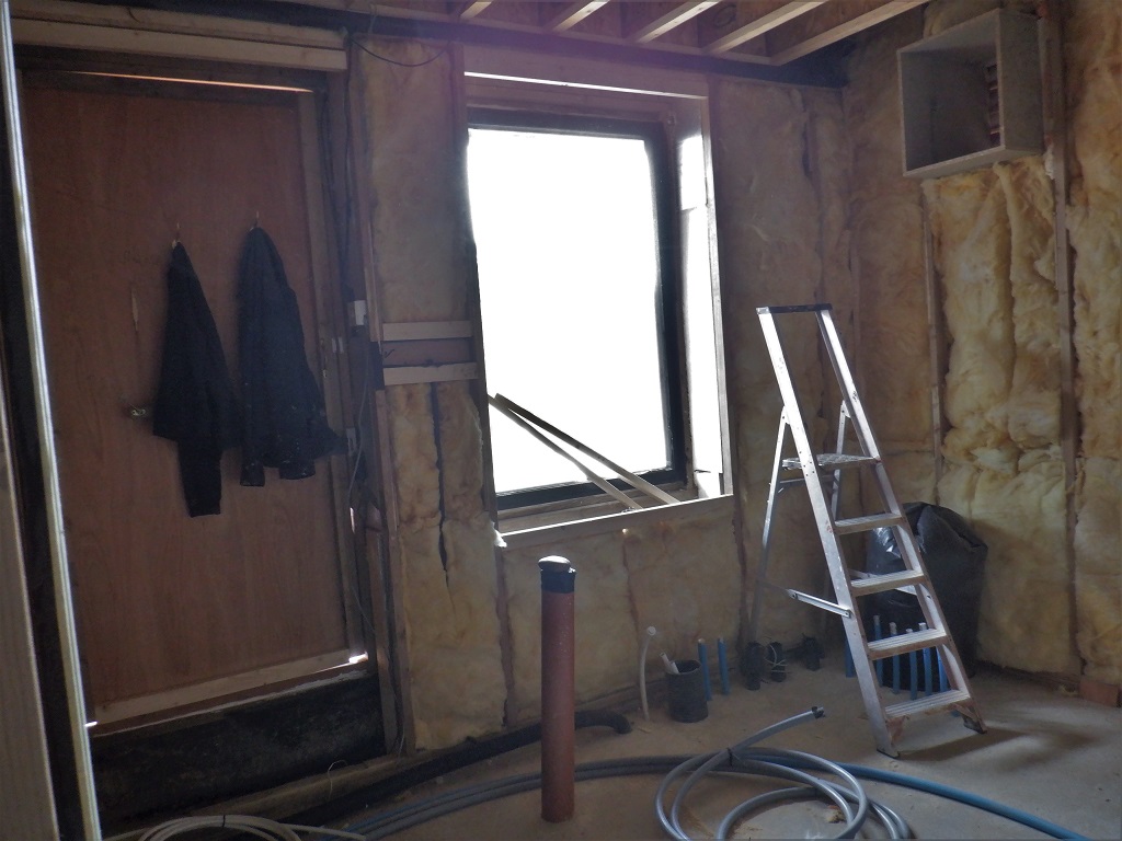
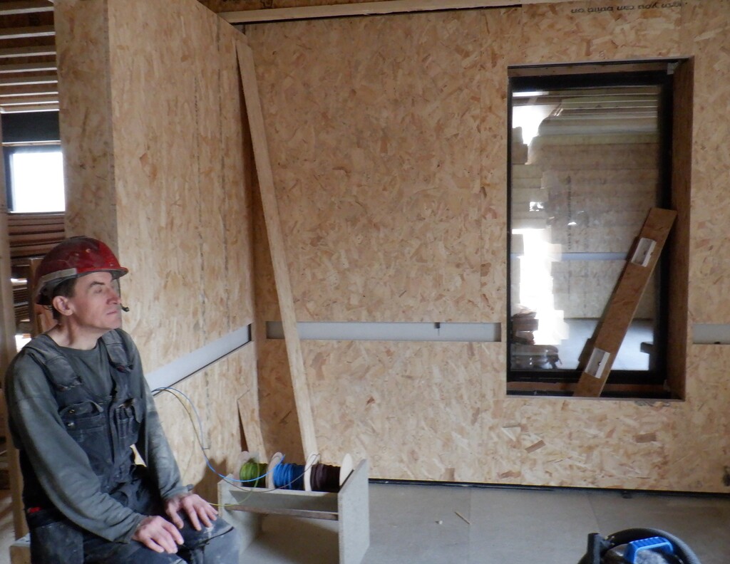
Now that we have the basic shell of our cupboard completed, we could move and build a proper electrical switchboard, to hold the consumer unit, fuses, junction boxes etc. all in the new cupboard. We have located this equipment to be at the left end of the cupboard, just near the window so we can just open a door above the worktop and gain access to the cut-off master switch and individual switches for each piece of equipment that will be inside the so called “Engine” room for our house. We also installed a row of temporary sockets to use whilst building. It took a day to get everything moved, sorted and made neat and tidy but we now have a solid foundation to grow the electric system for the whole house, the only bit left to do, is to hire an electrician to “plumb” in a unfused tap into the main distribution panel in the garage immediately after the smart meter etc.
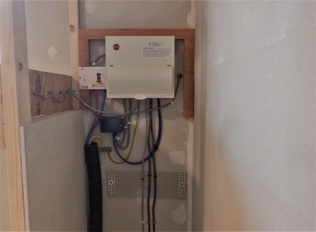
New-consumer-unit-and-temporary-wiring-1
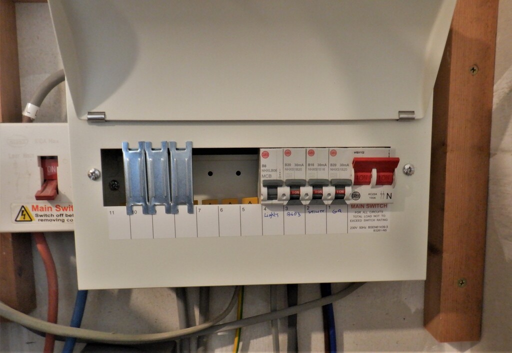
New-consumer-unit-and-temporary-wiring-2
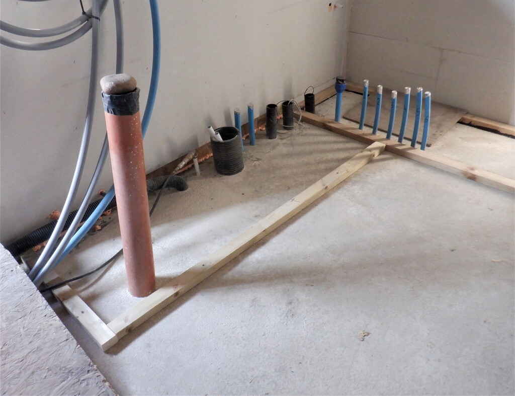
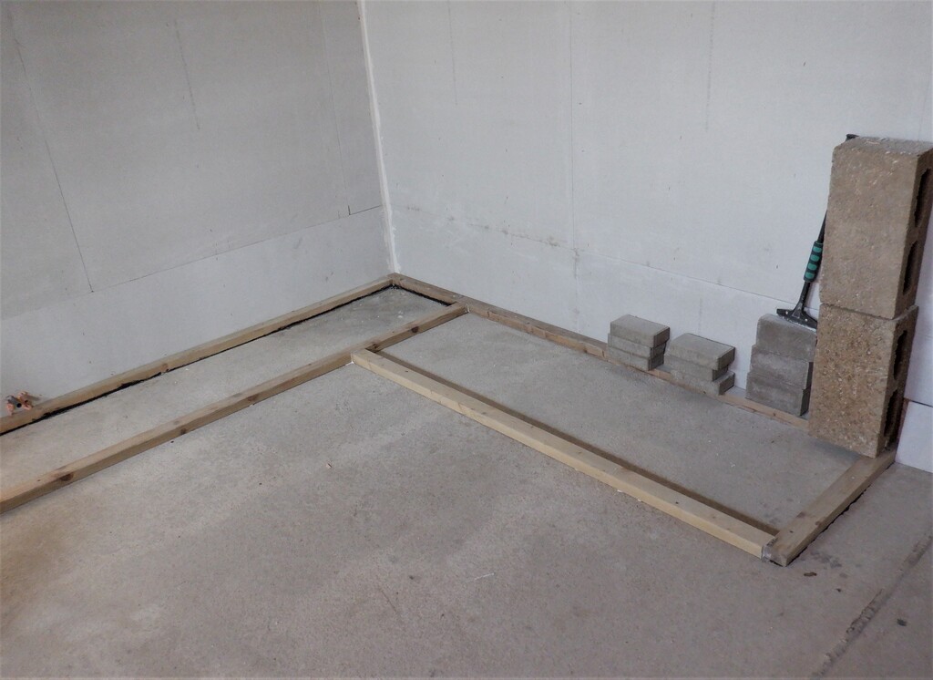
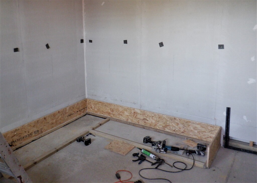
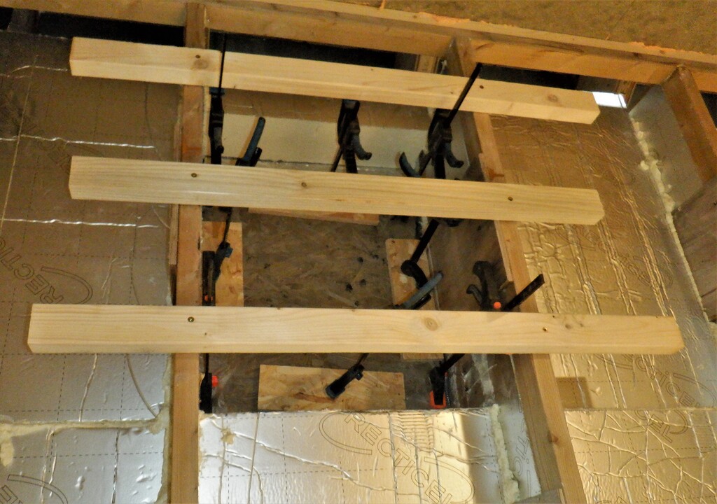
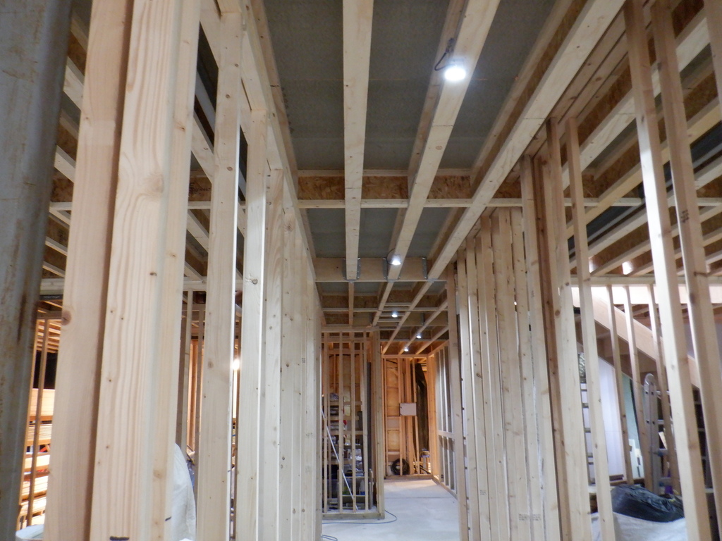
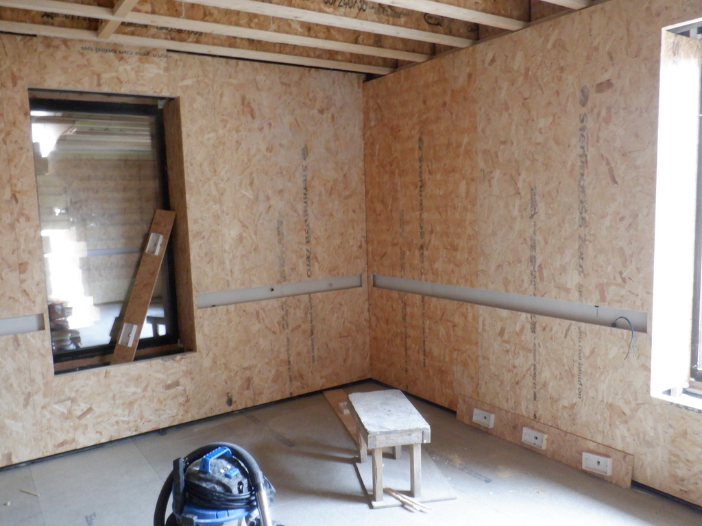
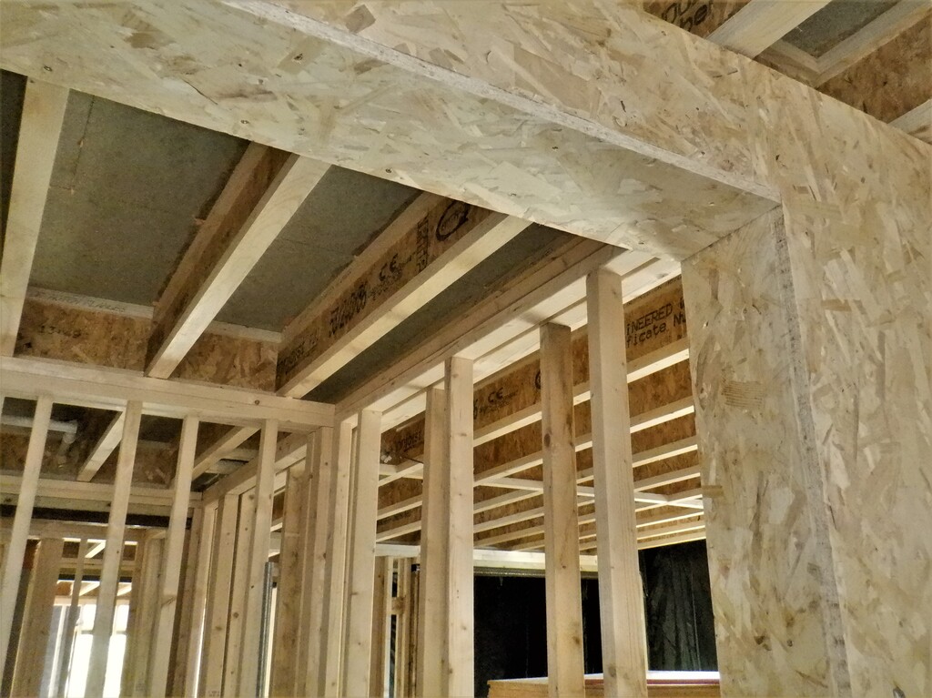
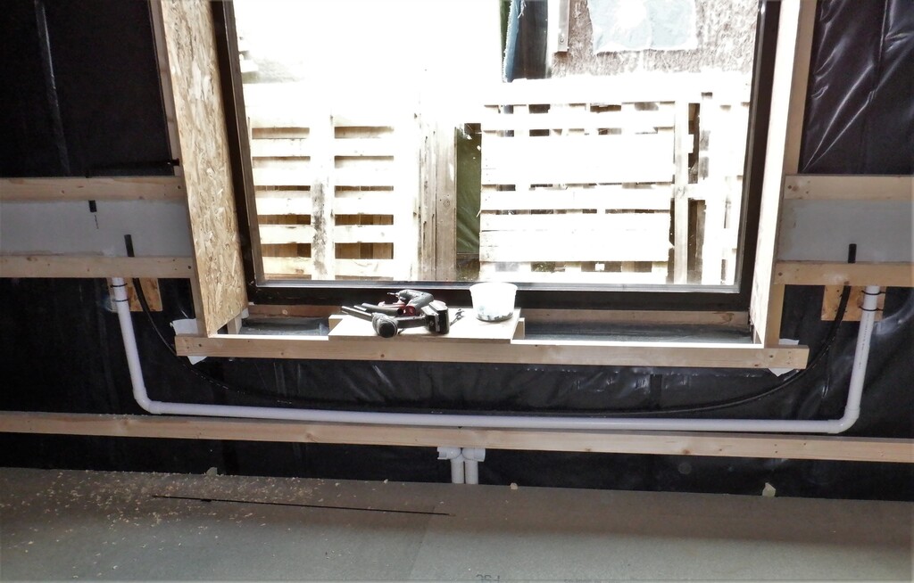
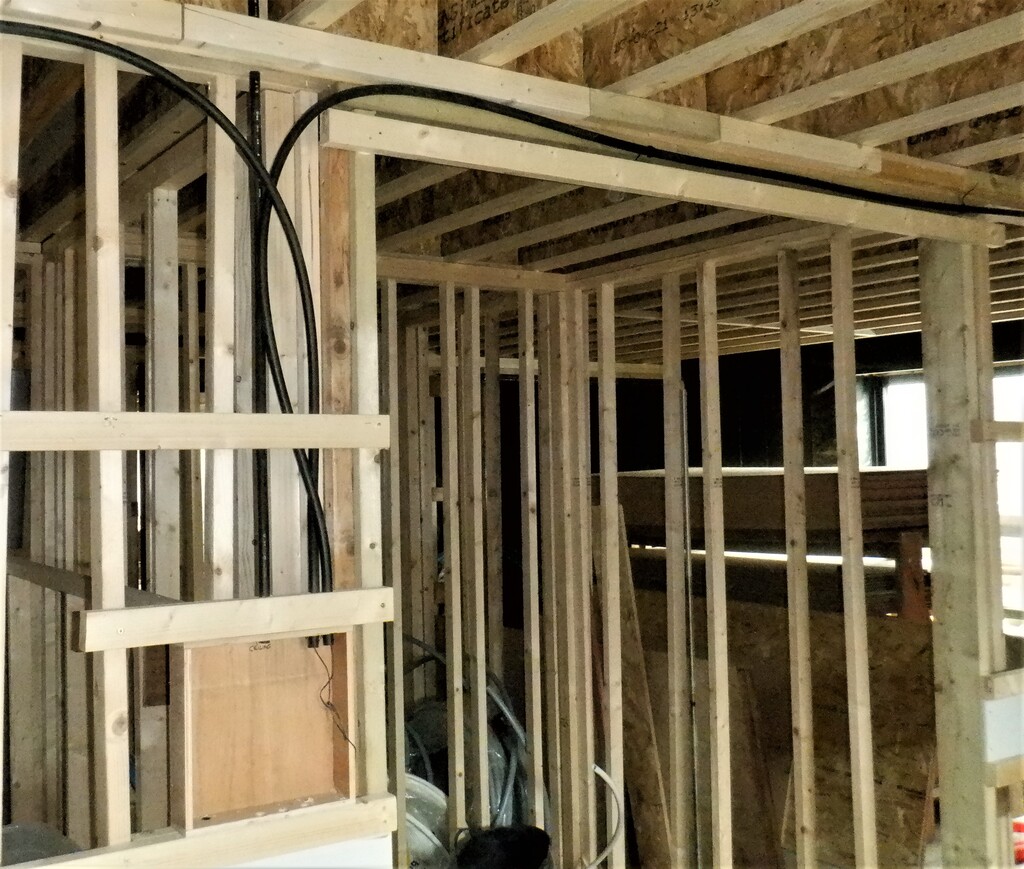
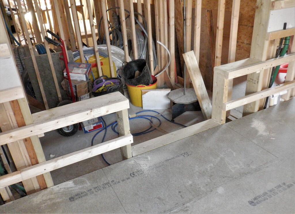
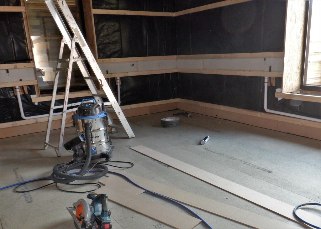
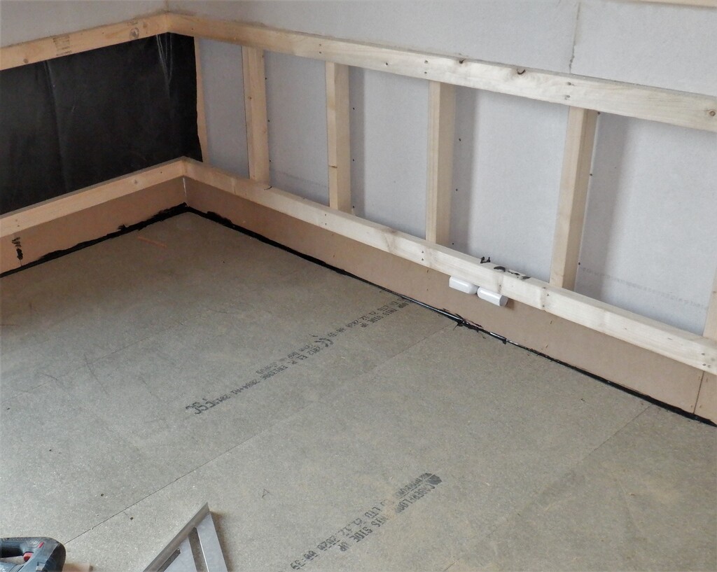
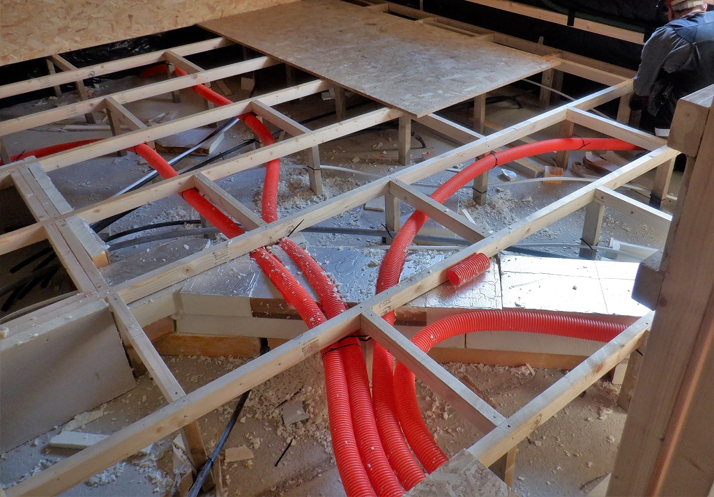
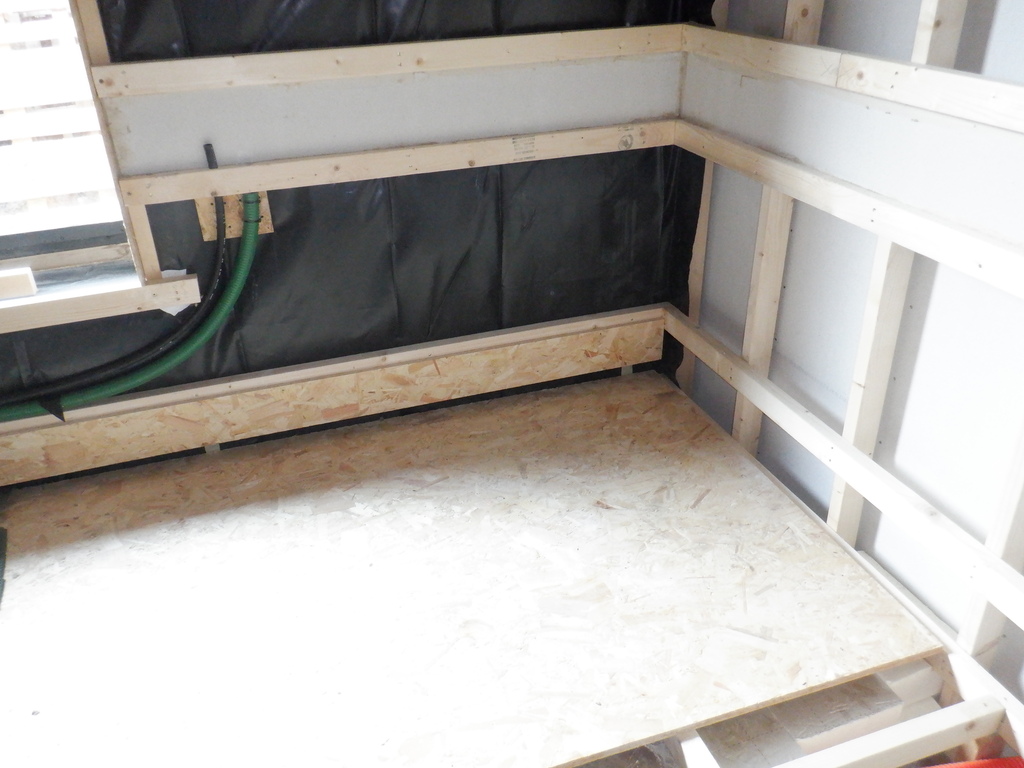
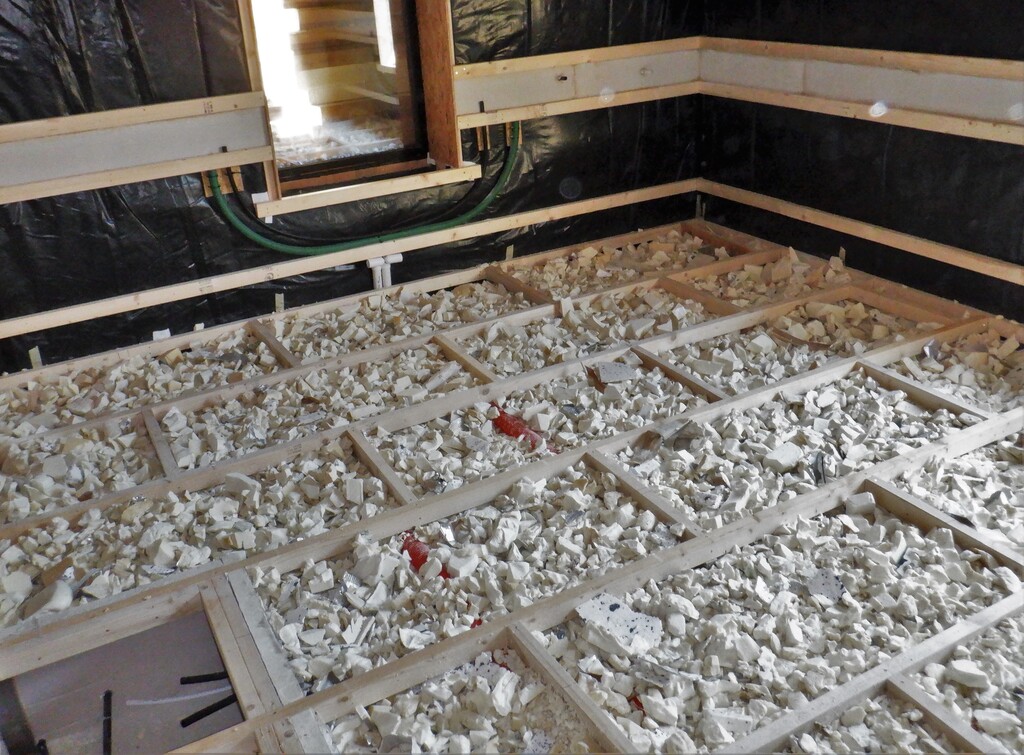
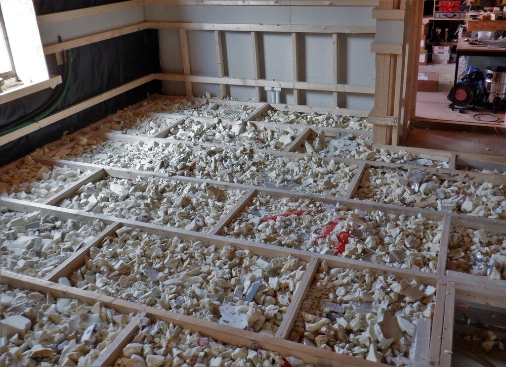
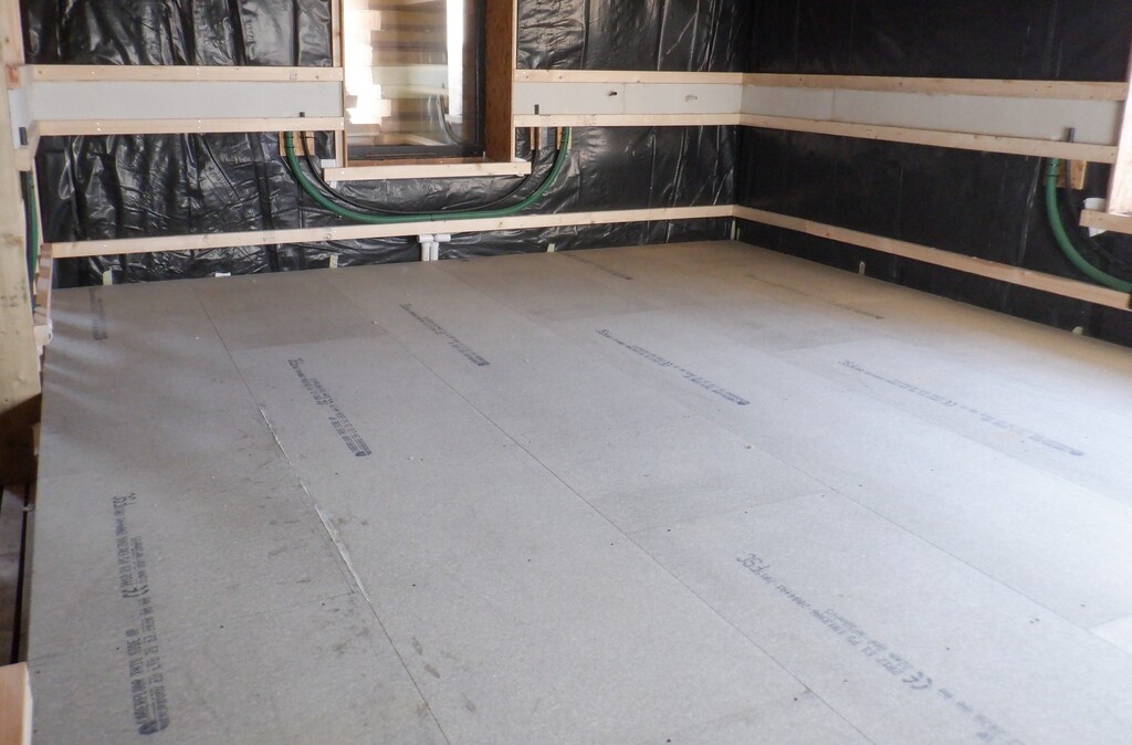
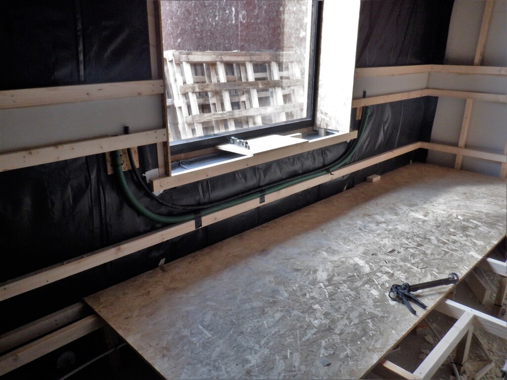
The remaining day and a bit was spent constructing the grid like support framework for our floorboards going across the room, making sure we had room to lay down our air ducting which is our largest item that lives under the floorboards, to get across the room and diagonally towards the door and into the hallway.

Utility-floor-support-grid-1
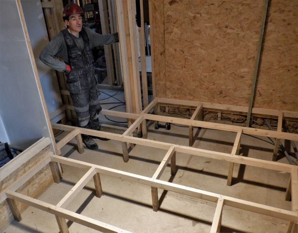
Utility-floor-support-grid-2
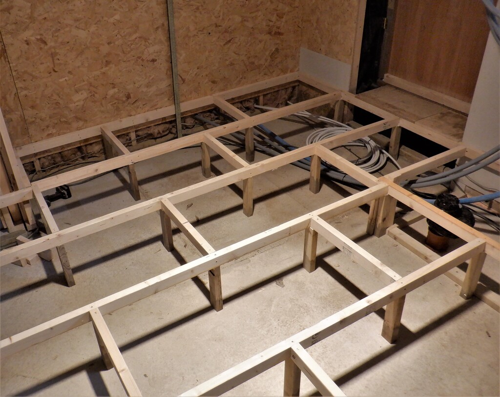
Utility-floor-support-grid-3
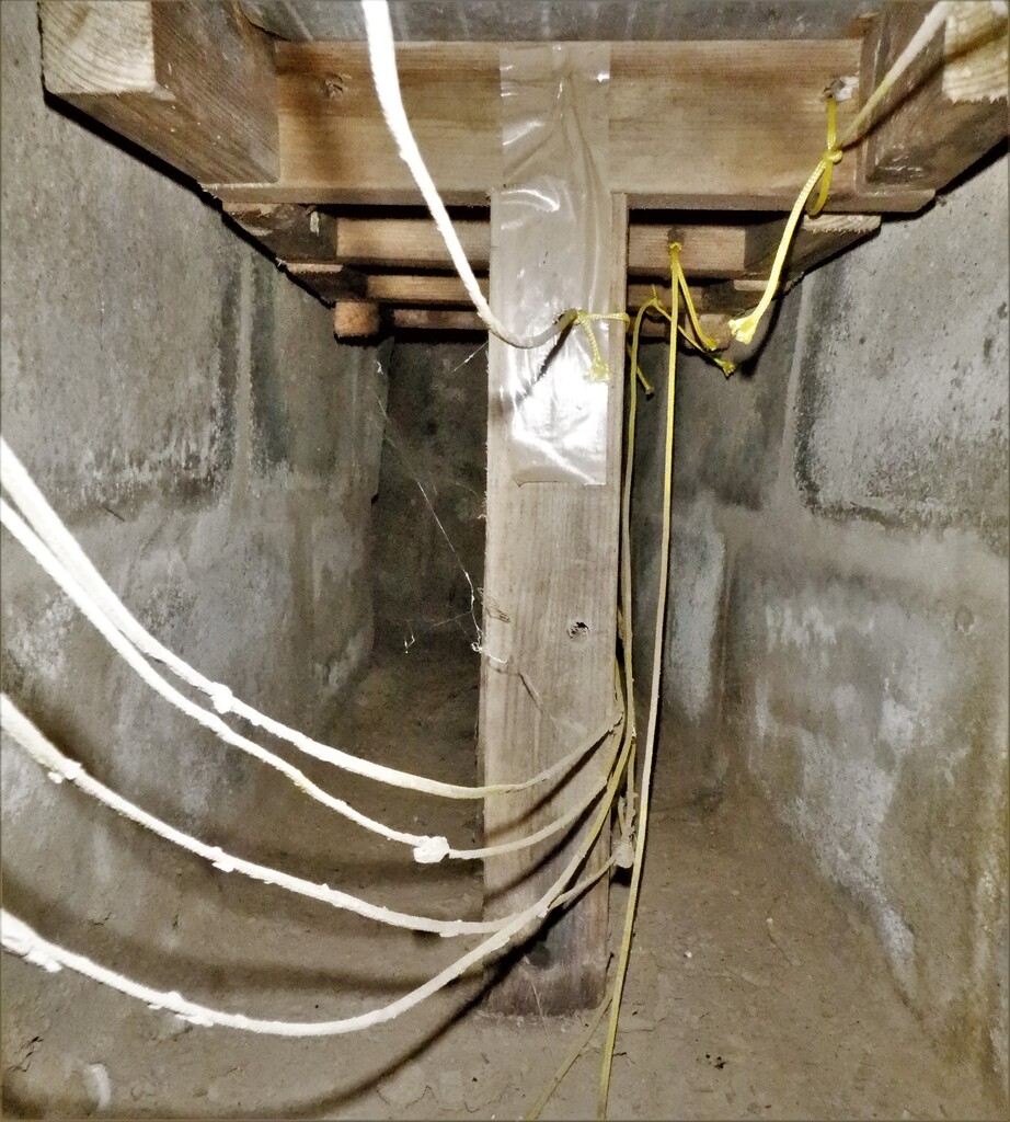
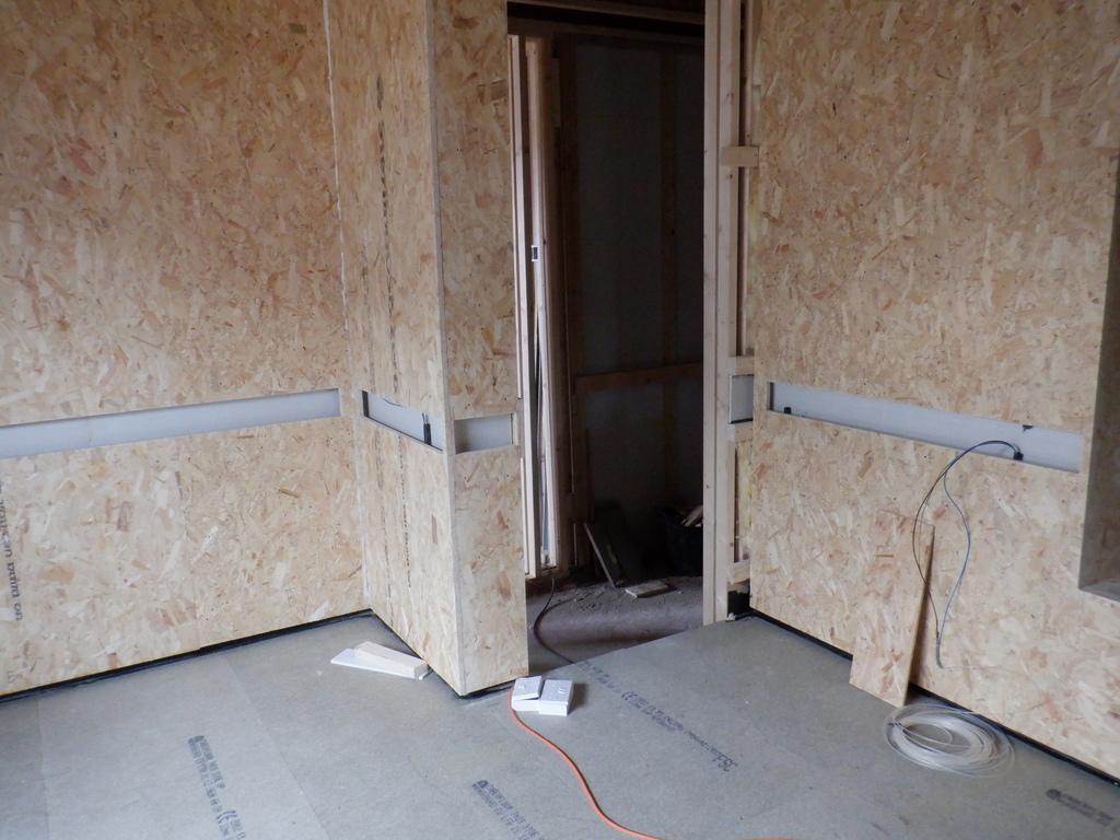
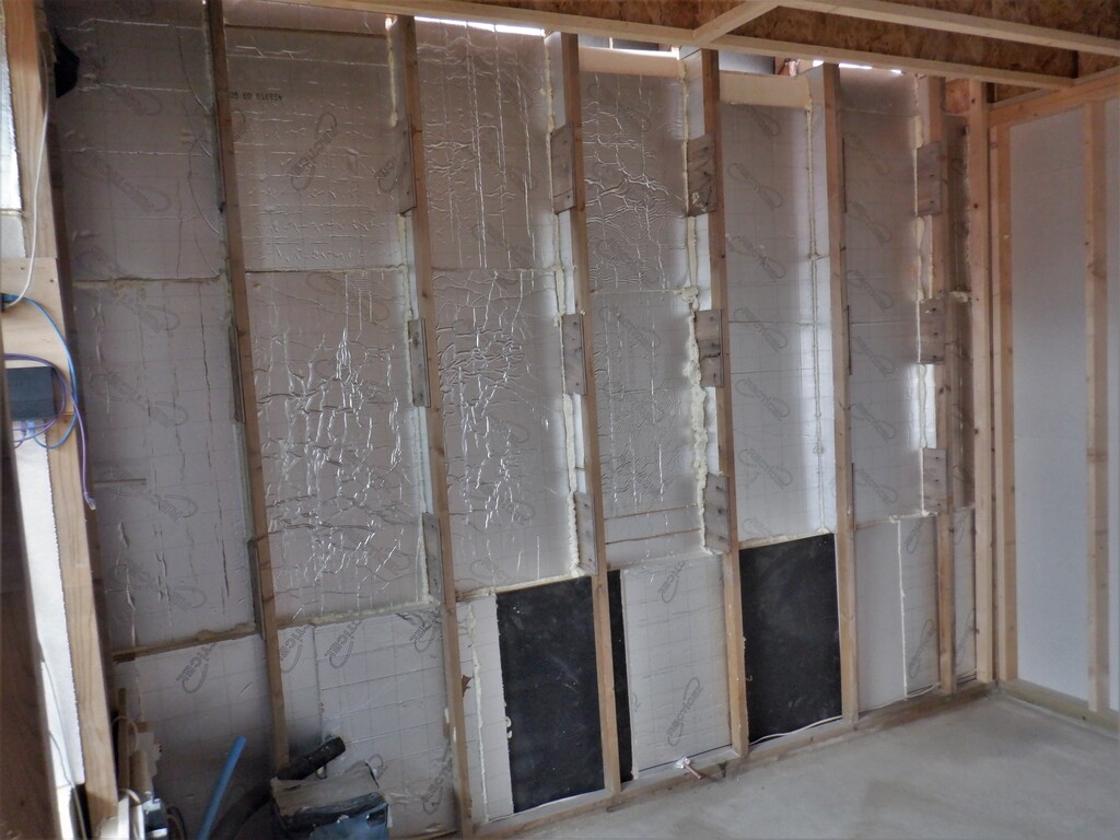
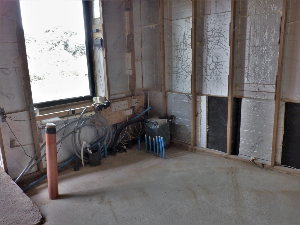
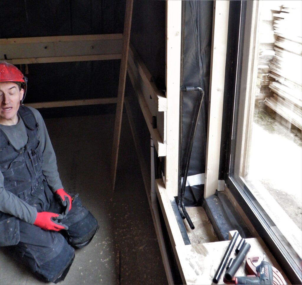
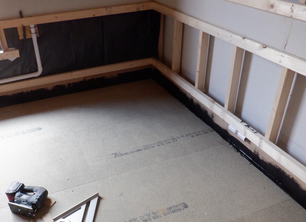
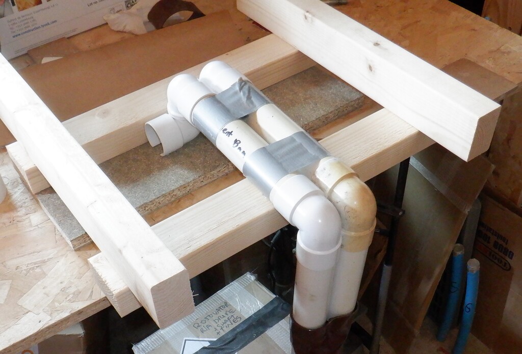
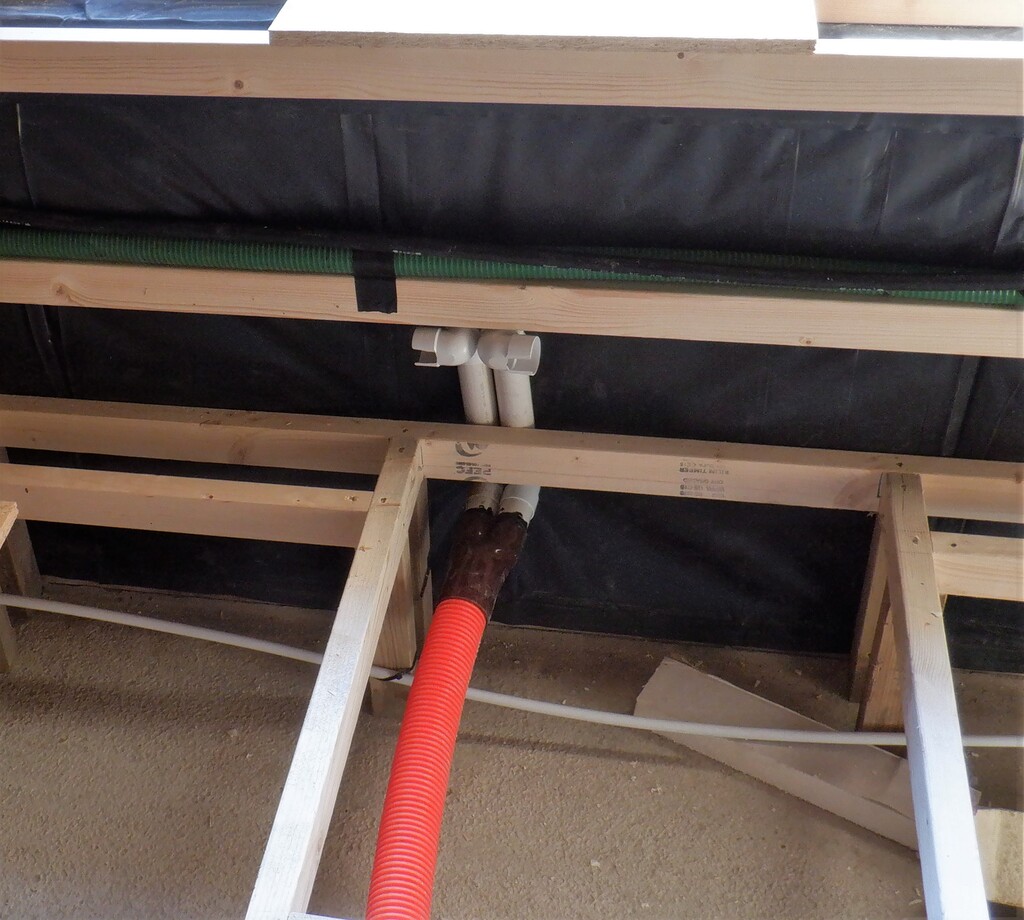
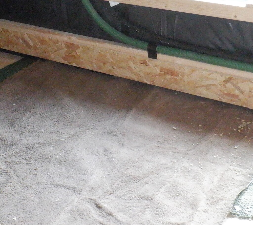
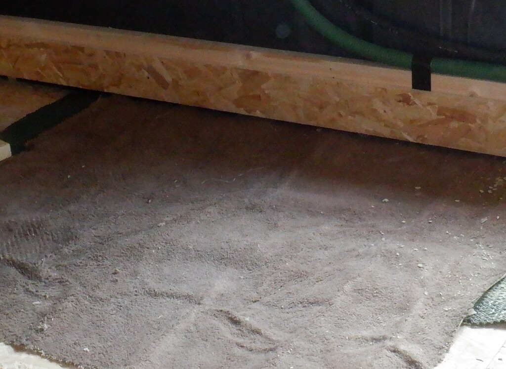
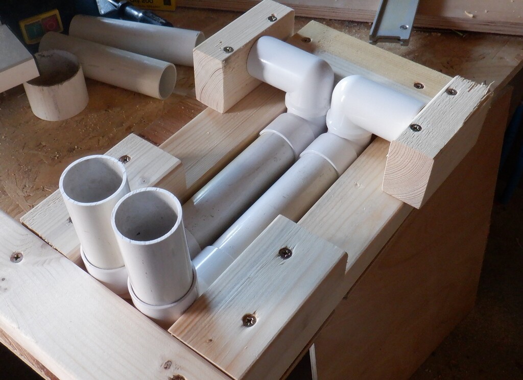
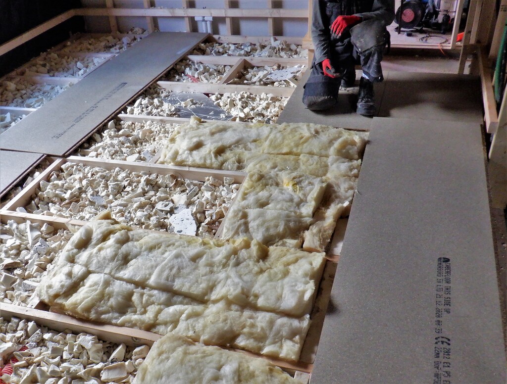
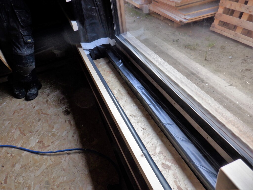
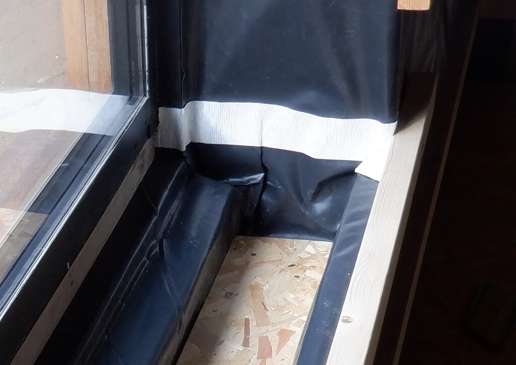
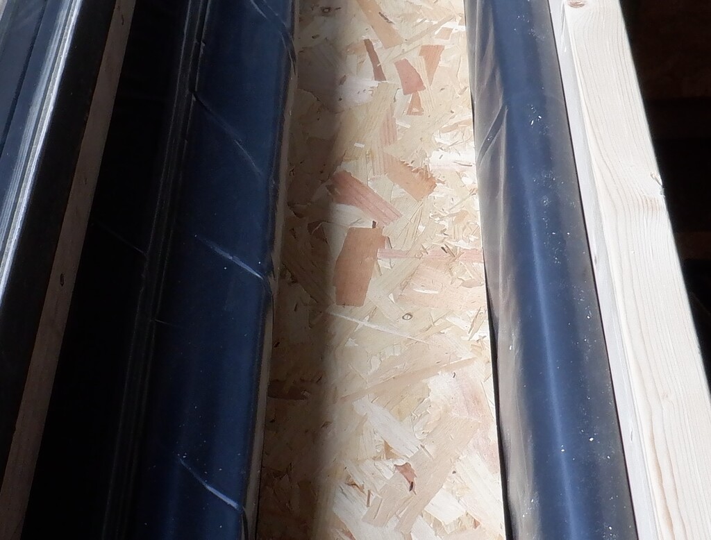
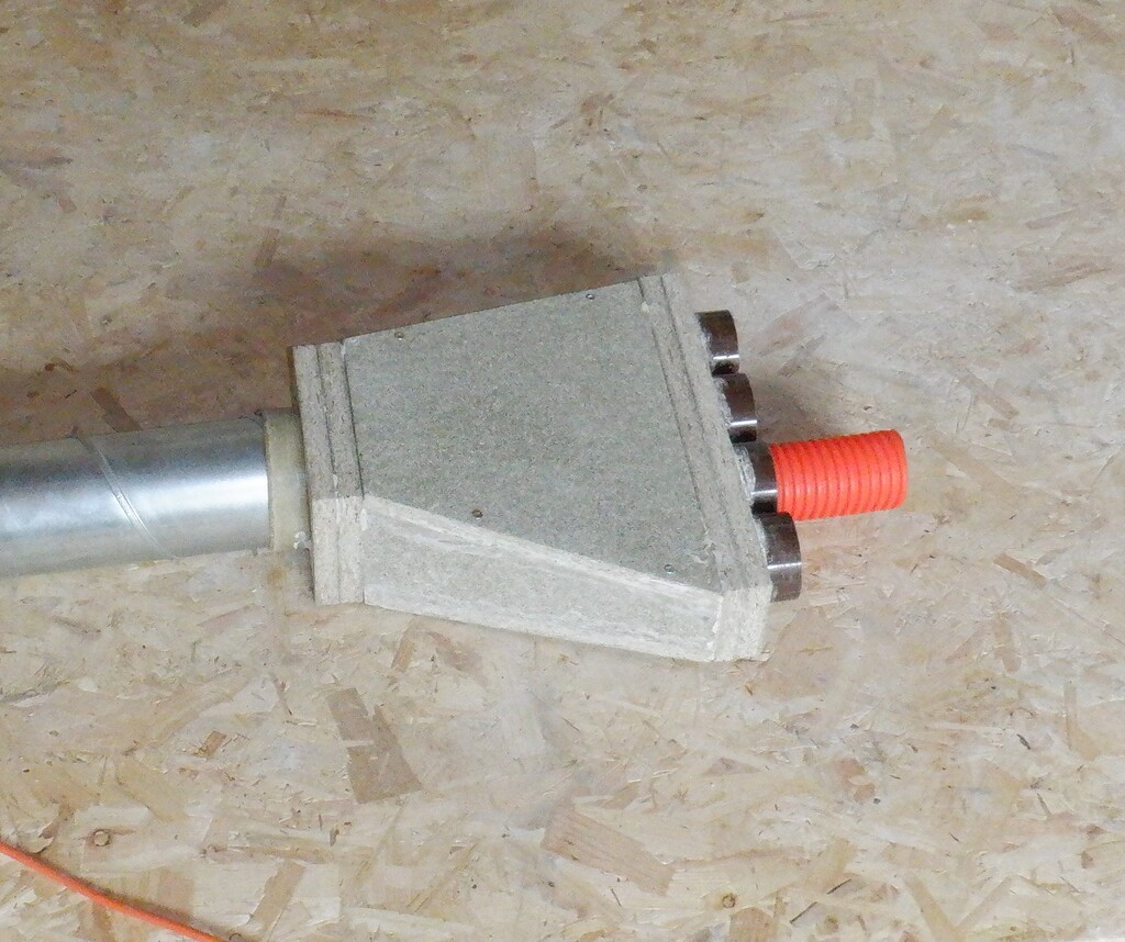
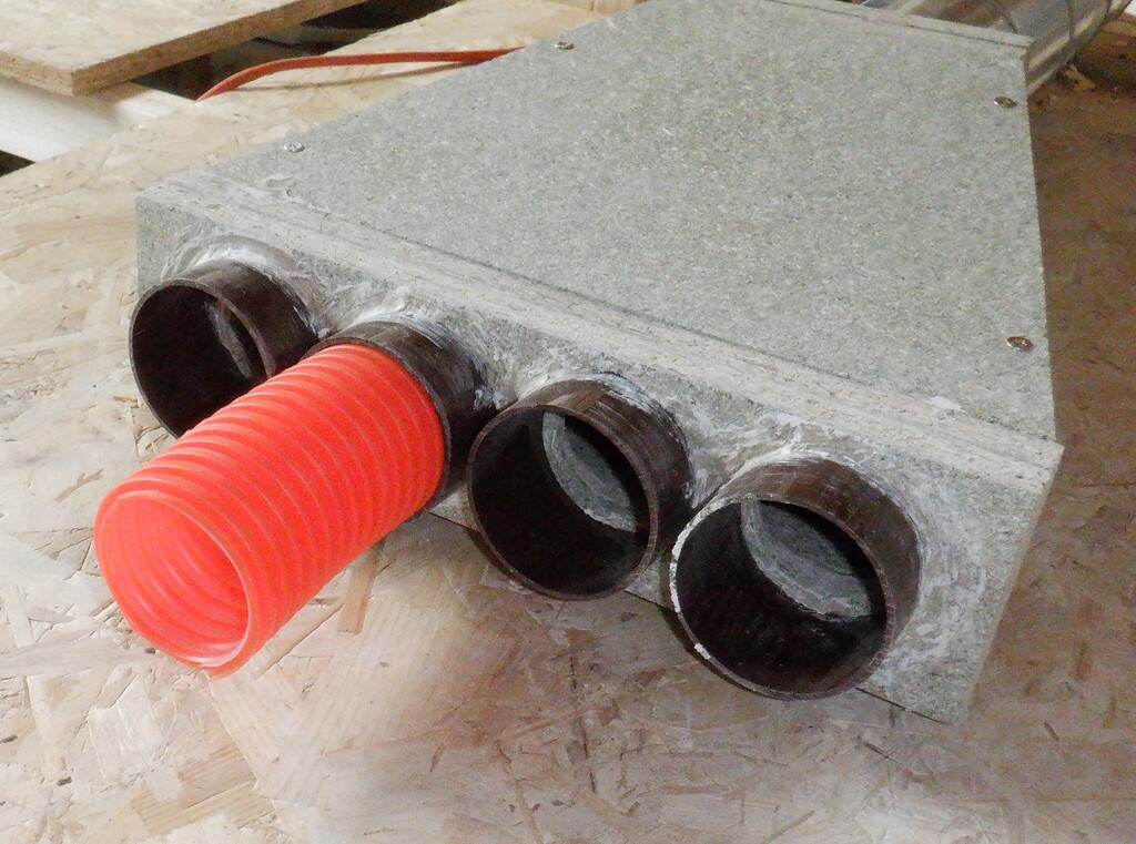
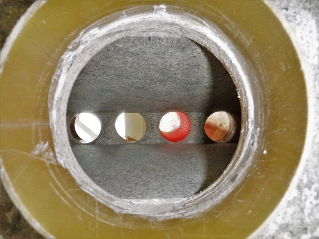
And then start putting in the insulation pieces that encapsulates the hot water “flow” and “return” pipes, snaking across towards the sink under the window and sorting out the conduits that needed to cross over etc. One of those pipes, is the main sewage pipe going down into the concrete and we bought a module that allowed us to have the ability to plug in four separate 40mm diameter waste pipes, coming from the sink and washing machine plus also any condensed water that drops out in the air conditioning sub-systems.

Start-of-Heating-pipe-crossing-the-room
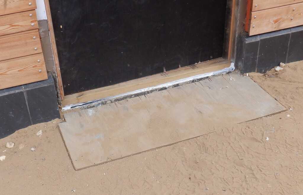
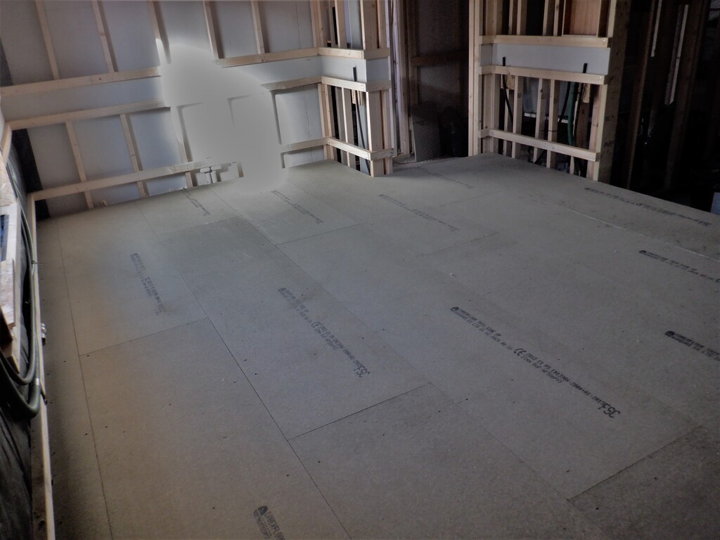
Next week, we will continue with that process of sorting out the hidden pipes and conduits so we then can put down a strip of proper and permanent floorboards in front of the door and window which in turn means that we can build the sink worktop and the cupboard and drawers that goes underneath. We are just planning a rough and tumble worktop for the time being, just using some OSB material we have lying around so we can have a working sink sooner than later.