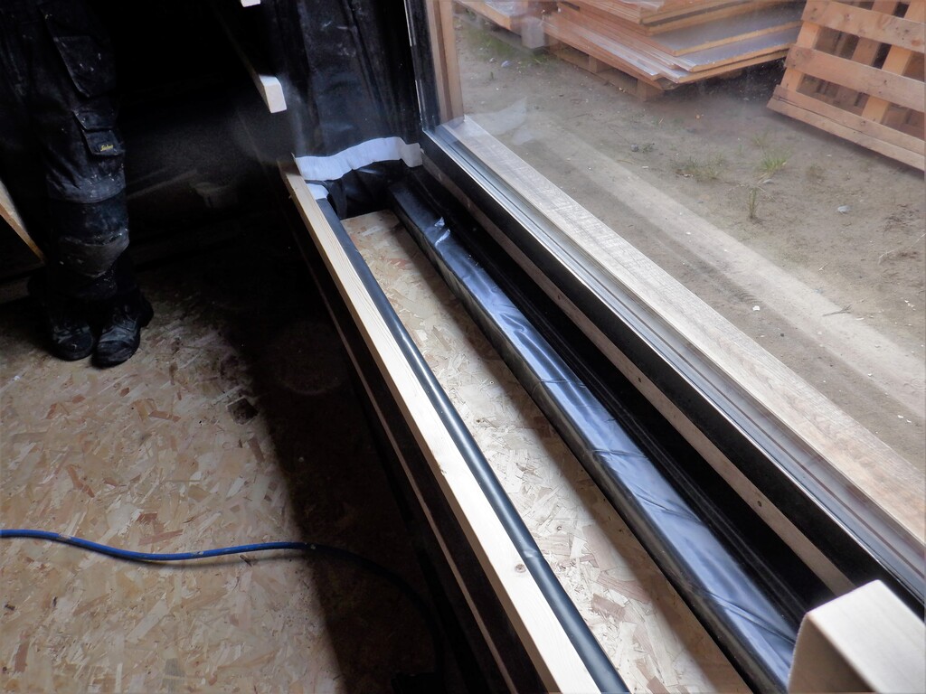
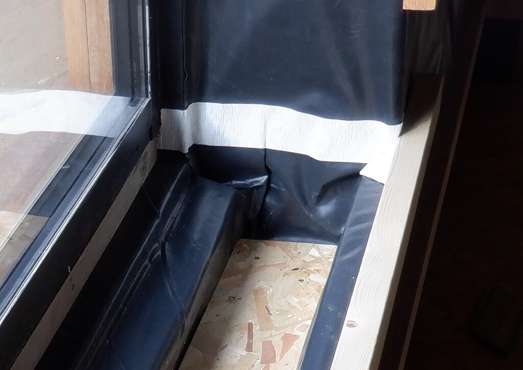
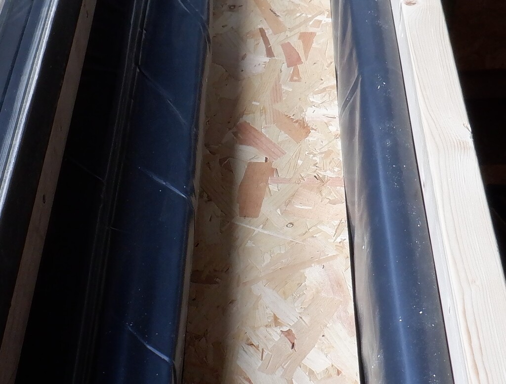
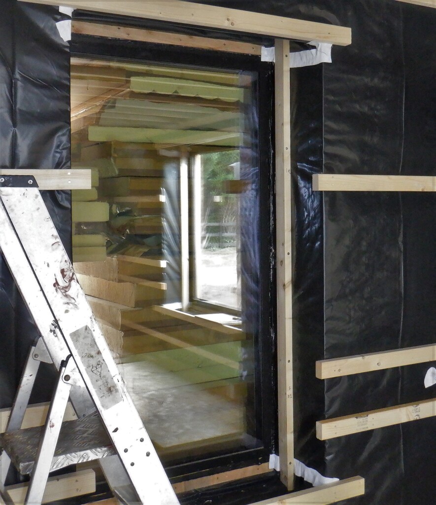
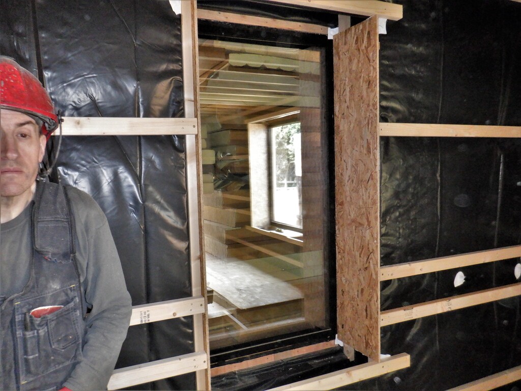
We continued with the work on Bedroom 3 and getting the floor, walls and windows ready. Whilst we are waiting for the deliveries, we got on with finishing the windows by putting the plastic vapour barrier around the bottoms and tops of the two windows. The first task we did was to insert small pieces of 25mm thick foam boards to encapsulate the last exposed bit of the concrete wall under the window and this will reduce heat losses and avoid condensation inside our window module. It was then a case of bending and folding the plastic up and over down into the chamber and back up again towards the oak frame under the glass. A slab of OSB 18mm thick board was then fixed into the bottom of the chamber to provide a mounting surface for the mechanical elements for our automatic blinds that will go up between the two pane of glass. The other piece of the black plastic was then inserted at the top end of the window to basically do the same job of sealing the wall structure from condensation derived from wet air generated by us human beings. The second smaller window was also done in a similar manner.
Vapour-barrier-in-base-of-window-1
Vapour-barrier-in-base-of-window-2
Vapour-barrier-in-base-of-window-3
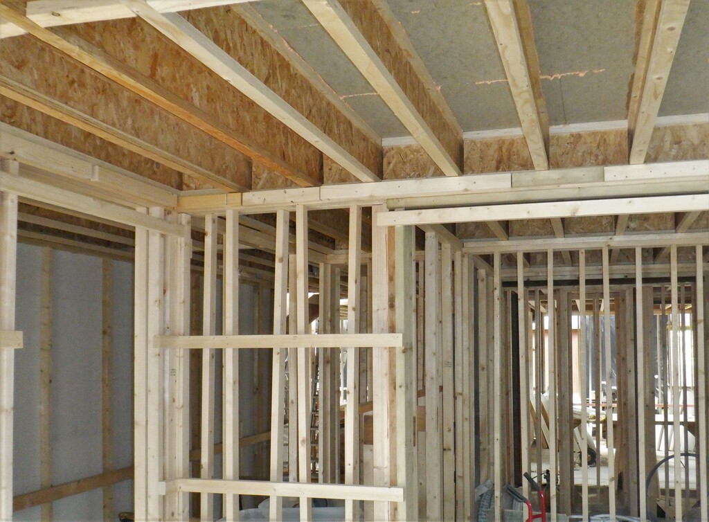
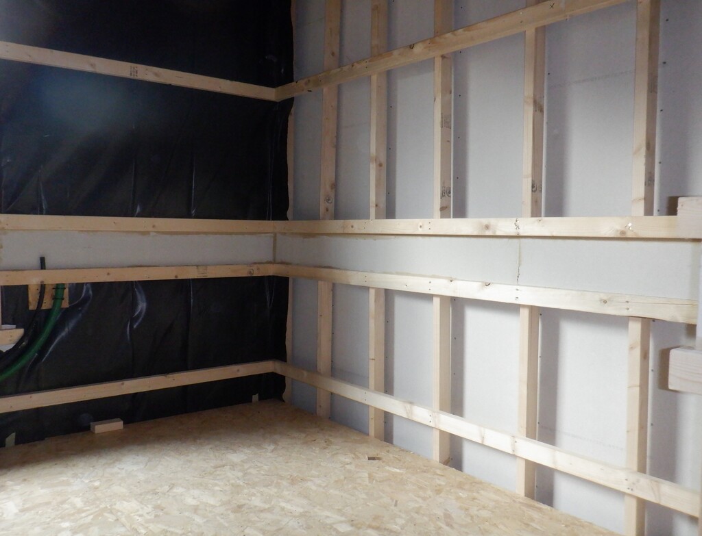
The next job was to attach a line of left-over CLS pieces to run all the way around the room at the ceiling level. This line of CLS timber will support the top of the OSB wall boards, with a short section having had the timber planed down to remove 11mm to cater for the extra strong lintel we built over the large window that is needed to support the first floor joists etc. Then we did the middle support rail as well so that concludes the majority of the support CLS timber all around the room. The next short pieces are going above and below each window and above the main door and the en-suite too. The height of the upper rail will define the internal framework for the structure of the doorway and this distance is 2206mm from the floorboard surface. This will give us room to insert the Oak frames and provide clearance for the flooring covering (like carpets etc) and have a 7foot I.e. 2134mm tall doors.
The windows also are set at this height so that both the windows and doors will match up with their openings, with the seats for the windows themselves will be set at 500mm off the floorboards. The seat will probably be 20 to 24mm thick Oak planks glued together and in the order of 365mm deep with a bull nose front edge sticking out into the room by 25mm or so.
Last-two-rails-installed
Then, still waiting for the delivery of our conduit tubing (we enquired and the supplier is having trouble in sourcing the 40mm twin wall conduits), we got on with doing the side walls for each window. A piece of CLS timber is needed at the back to extend the original framework around the window so that there will be sufficient support to hold the second oak frame that will hold the inner pane of glass . We had do some major planing of these timber pieces to make them line up with the original CLS so that the new oak frame will match up together. Long screws were drilled and driven through the full depth of the 63mm direction, to secure each piece into place. then yet another piece of CLS timber was placed, but this time at the front of the window section, just behind the horizontal rails, to form the vertical corners of the walls where the windows are inset and the fermacell “plaster boards” will provide the finishing surface coming along the wall and turning in towards the windows.
Window-sub-frame-exstension
Window-side-panel
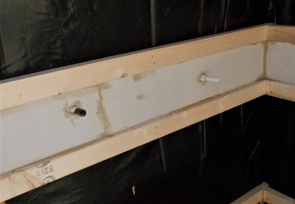
One of the other tasks we did this week for this Bedroom, was to drill clearance holes through the horizontal timber pieces that forms the space for the Utility Channel and these holes had short length of various sizes of conduits and pipes inserted. These conduits helps to transfer the cabling from one side to the other of an opening like a window or door, to the other side so that the cables can carry on around the Utility Channel. There were 20mm diameter polyethene black pipes to carry the mains AC 230V supply and a second larger diameter plastic conduits measuring 37mm overall but 32mm internal, to carry all other types of cabling like network cat5, speaker wires, DC voltage power and other low-voltage types. We did the doorway around the en-suite plus also the two windows too.
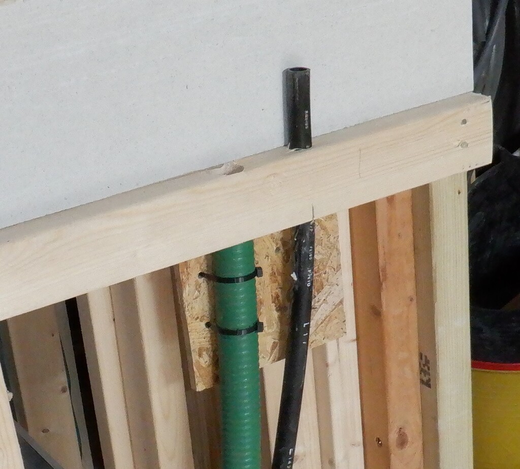
Conduits-fixed-to-base-of-utility-channel
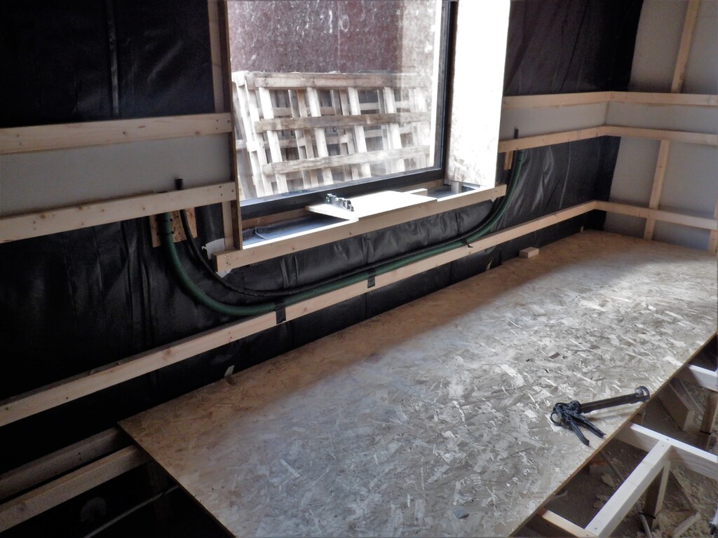
Conduits-bypassing-the-window
At last, our Flexible Twin Walled Plastic Conduits Arrives, but only our 63mm and 100mm types. We are missing the 40mm diameter one as it is in very short supply across the country and beyond. We are looking for alternatives to help us guide our low-voltage cabling around windows and doorways, we had some old wide bore water pipe so we used that one instead (it is the green ones).
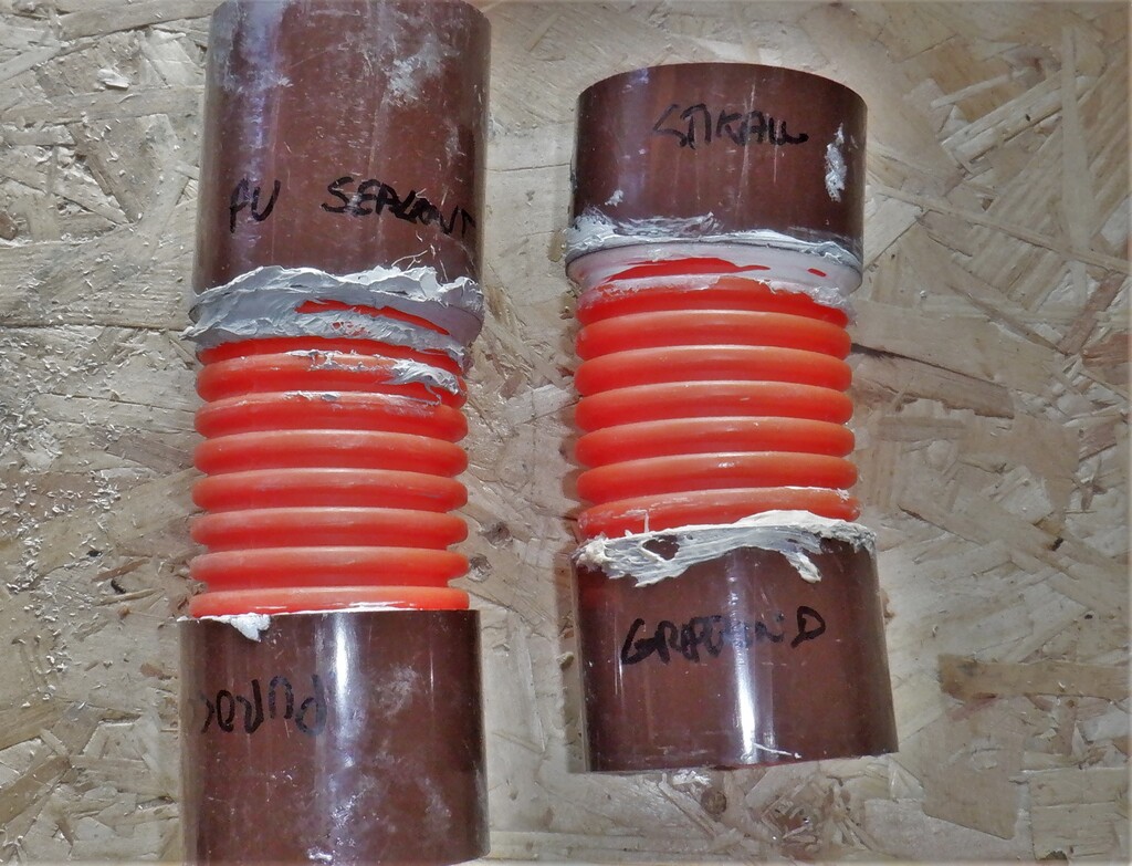
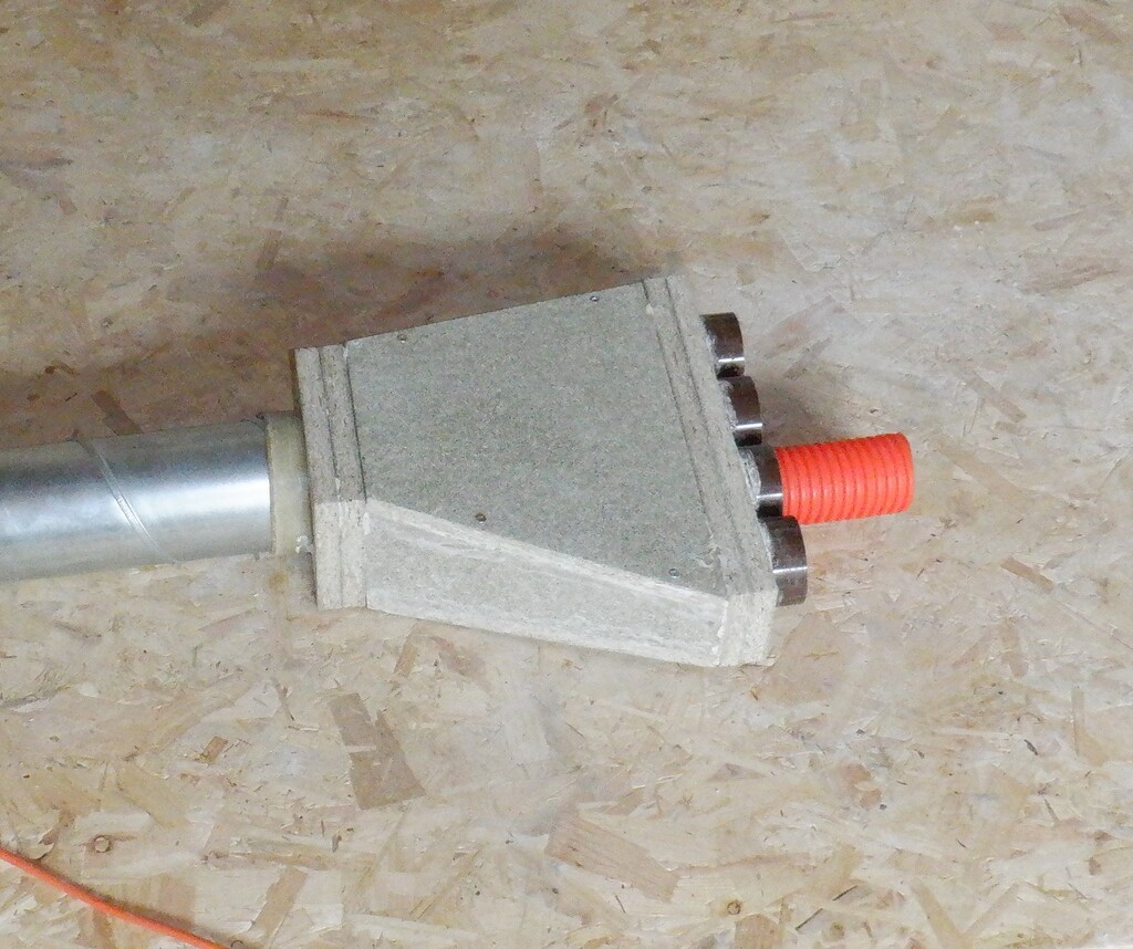
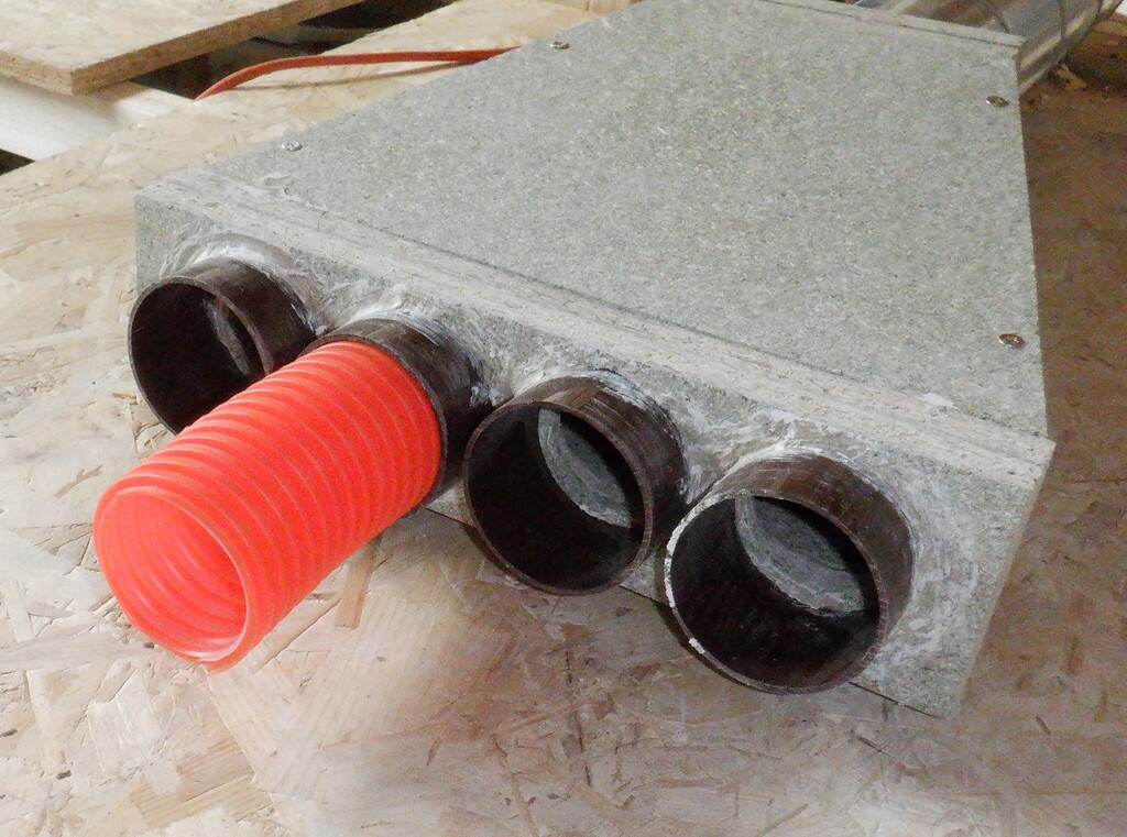
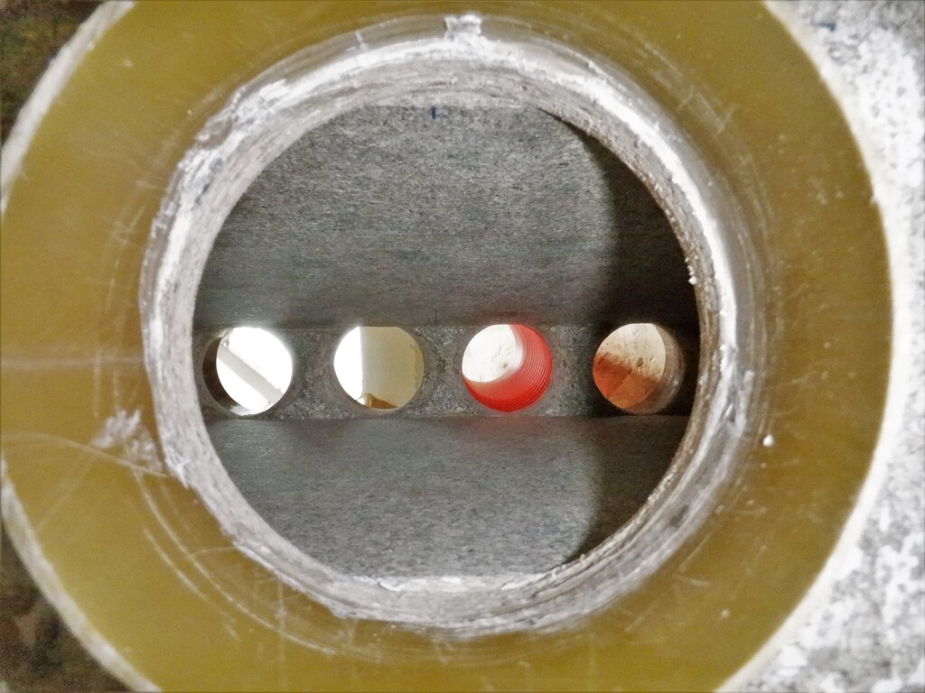
Now we could and did design and construct an air conduit splitter module (a plenum), which takes the 100mm feed coming from the main air duct, and splits the air flow into four separate 50mm streams to go off across the room to the four walls. We used left-over chipboard floorboards to build a triangular shaped chamber which squeezes from a 100mm gap, down to a 50mm spacing to spread the air out sideways, into four holes. The five holes all had short lengths of plastic pipes inserted and glued into place so we can just slide the conduits straight in and out to provide a good strong and tight seal. There were four 68mm wide pieces of pipe plus one 110mm wide sewage pipe, all ready for installation later on. We also did a small test of different glues and sealants to make sure that the plastic pipes we have used will stick to the twin-wall conduits and we can happily report that all four types we tried all worked just fine (PU sealant, PU construction glue, general purpose construction adhesive called Grip Bond and a modified polymer one called Stixall).
Testing-joining-pipe-to-twinwall
Room-air-supply-plenum-1
Room-air-supply-plenum-2
Room-air-supply-plenum-3
The other task, the final one for the week is to slice up a sheet of our fermacell material, a gypsum mixed with recycled shredded newspaper board material, into 175mm wide strips so we can insert a backing panel in our Utility Channel, to both provide a surface to mount hooks and other lightweight items but also the fermacell layer will provide a fire resistant barrier to stop the spread of flames. So we took a sheet and sliced it up on our workbench table saw, set the fence to 175mm and cut six strips off one sheet. We went around the entire Utility Channel fitting each section with our new strips, occasionally having to trim the edges to make it fit and also in one section, we had two 20mm conduits sticking out the wall and had to drill a hole in the correct spot. We used the general purpose construction glue along the bottom and top edges, plus a line on each vertical leg and did the occasional vertical joint between fermacell pieces too.
Back-of-utility-channel-covered-in-Fermacell
Exterior-conduits-passing-through-back-cover
Another little job we did was to try out a test fit of some 6mm thick MDF board material to see how it looks and how it comes together, all to form the air dispersal channel running around the bottom of the wall, all the way around the whole room. We concluded that it will do a very good job so next week, we can look into doing that job.
Leave a Reply
You must be logged in to post a comment.