Blog

  • Fiddly Hidden Elements Completed in First Floor Joist Space

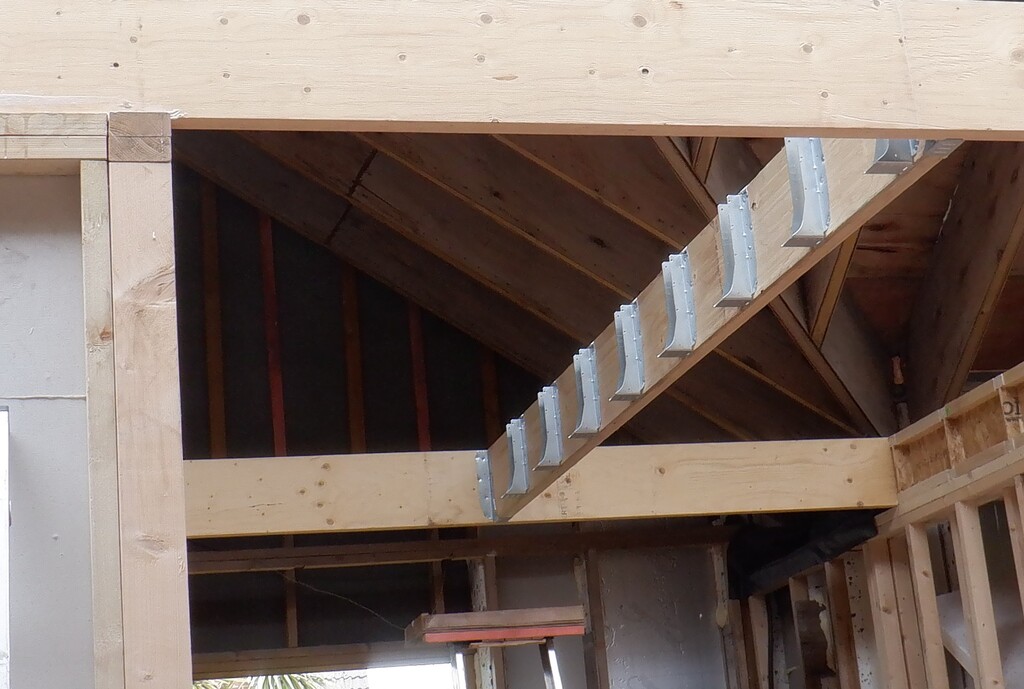
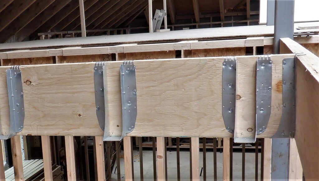
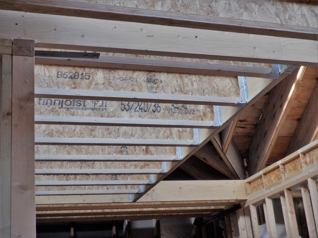
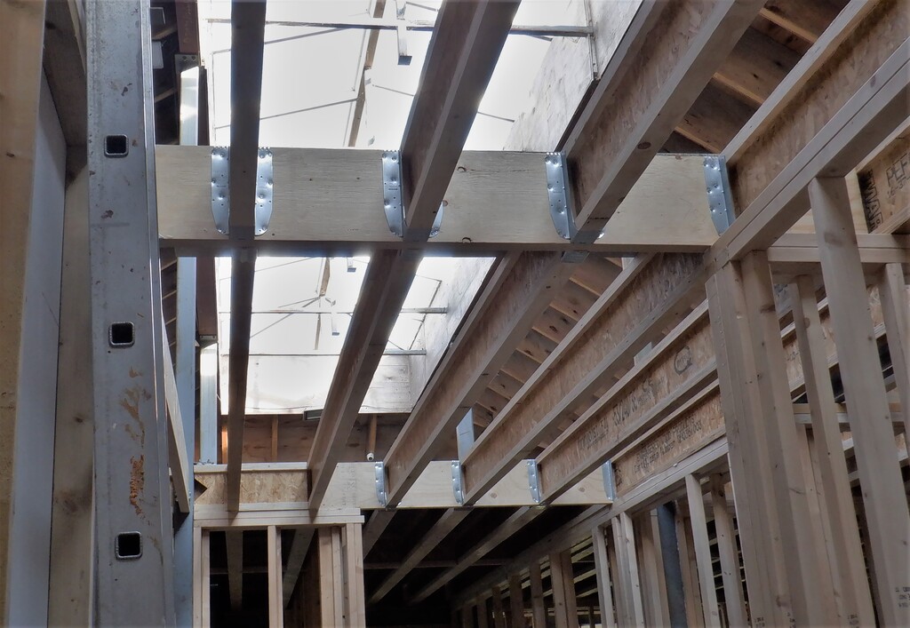
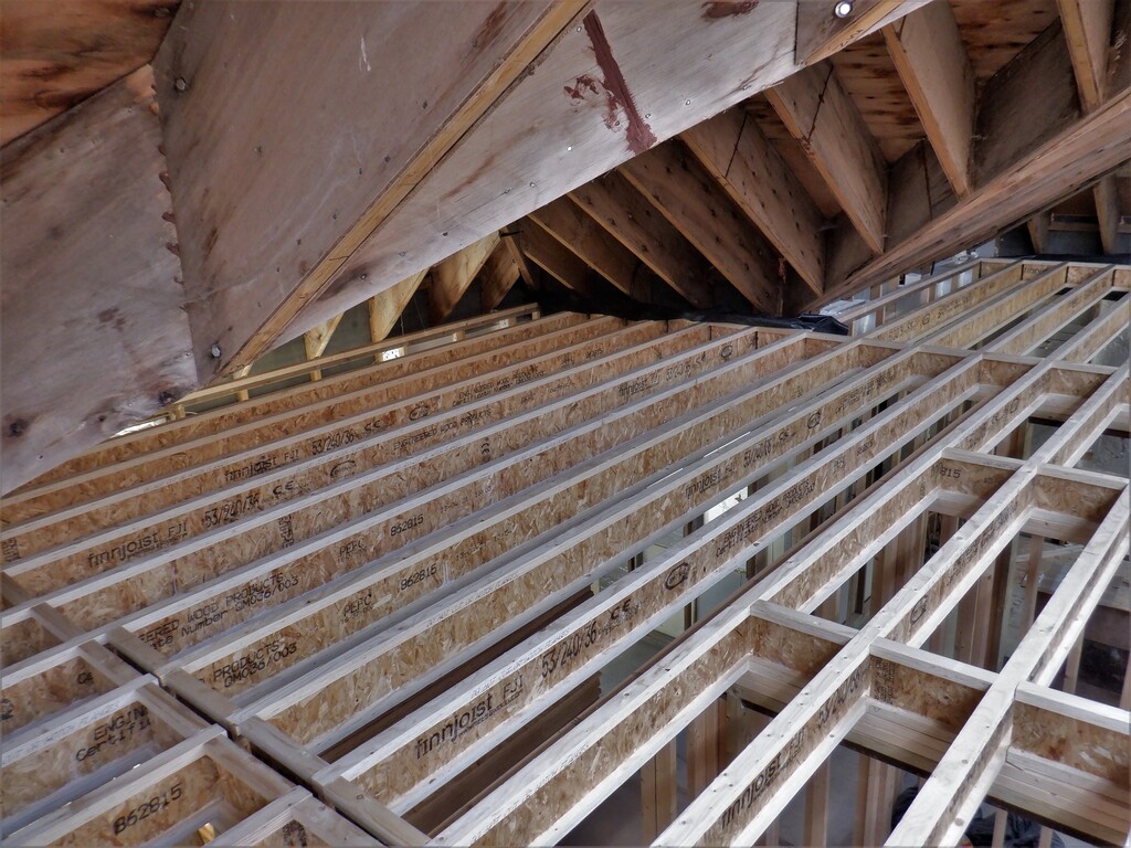
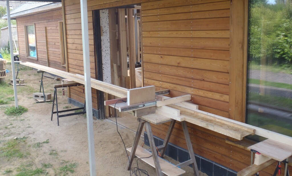
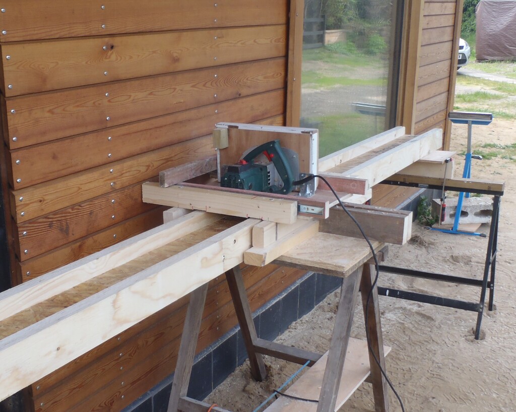
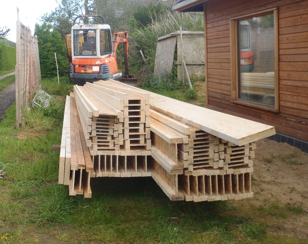
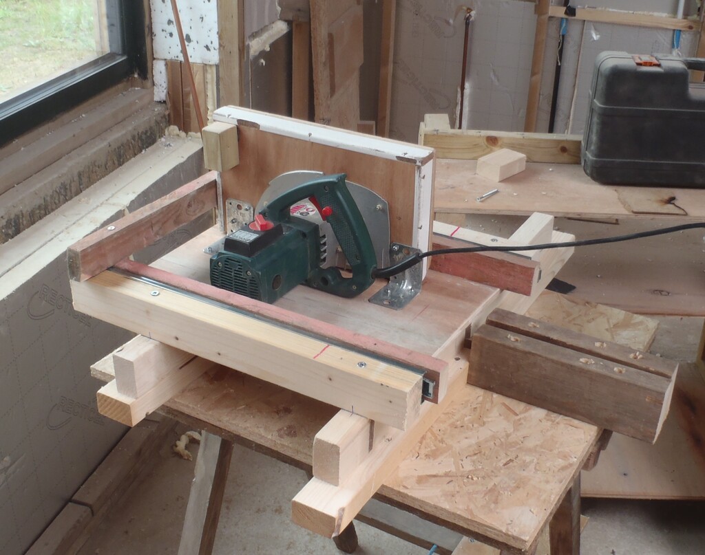
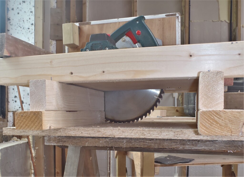
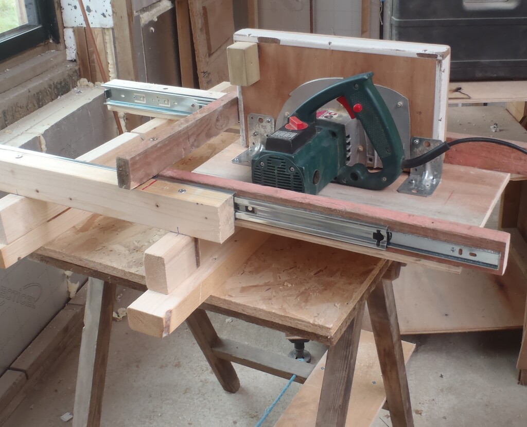
    This week was a chop and change kind of week, working on lots of different elements that needed to be done before we can continue in laying down the floorboards across the first floor joists. One of the last remaining tasks from last week was to glue and and nail the final four long I-Beams into place (these are going down the long hallway from the central part of the house and heading rightwards to the Utility and Bedroom 3 rooms) and put in the noggings to secure them at the ends. Talking about noggings, we looked at the structure of the first floor and counted how many more noggings we would need which came to some where around of figure of 60 individuals. We had 16 still left over from the last grand nogging creation so we sliced up three I-Beam left-overs, about 3metres each and then sliced up one complete 10metre I-Beam, to generate additional 44 noggings.
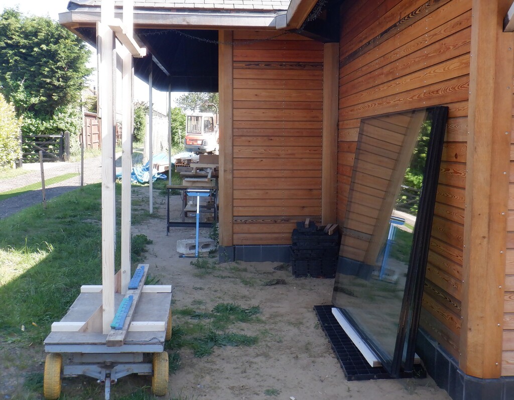
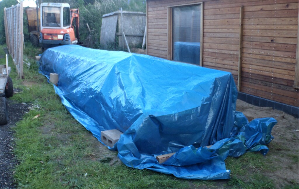
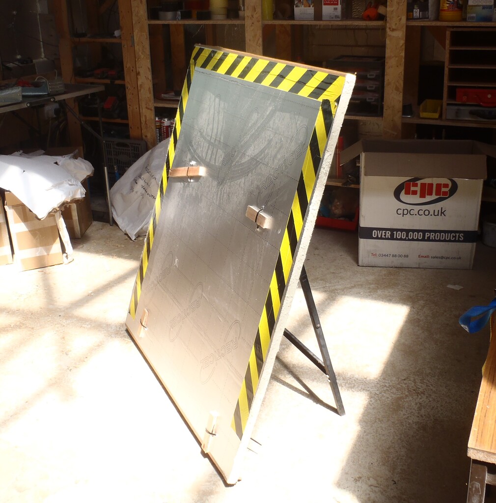
    With this done, our slicing machine have mostly finished all the bulk work so we dismantled the working area under our Front Door Porch, tidied away all the equipment and moved the slicing machine into Bedroom 1 for any odd jobs. Then we moved the final two 10metre I-Beams over to our Swimming Lane storage area for the long term (we will find something for them we have no doubts!!), folded up the tarpaulin, moved twelve concrete blocks and tidied away the wooden bearers. The front of our house is all clear again – hurray – Smile!

    So having done that, we could resume laying down floorboards but only a couple of rows. It took us almost an entire afternoon just to do one row, because it was the transition of entering into the larger space plus also there was two metal legs of the Skylight to navigate around too and we reached the next challenge. This is where we needed to install additional hidden elements that lives inside the joist space as follows ..
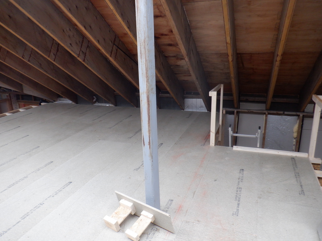
    The Cold Water Header tank Support lintel being the first one, we had made provisions during the construction of the walls by putting triple posts in the location where the ends of the steel lintel will sit so we just needed to hoist up the steel lintel. This steel object is another one of our left-over piece, this time, it is a 2.1metre large fat steel leg measuring 160mm wide by 80mm thick. These steel elements are supporting the Skylight hanging over the Great Room and we got three of them lying around in the Garage so it is ideal to be used as a lintel to support the large header tank and transfer the weight down directly to the concrete floor and not into the first floor structure. It weighed about 60kg so it took a bit of lifting from both of us to haul it up to the first floor. We then chopped eight pieces from a 2by6 timber to form short stumpy legs to lift the steel tube up so it is flush with the tops of the joists and the floorboards when it finally get laid. These stumpy support posts were 160mm tall and after slicing tiny bits off to get everything level, we glued the two set of four to form the two pillars and we stuck down the freshly scrubbed steel lintel into place. Finally, then we put small pieces of noggings down on either sides of the steel to make sure it is locked into place and won’t fall over or twist under the load of the header tank.

    Fiddly Hidden Elements Completed in First Floor Joist Space

    Water-tank-support-supports

    Fiddly Hidden Elements Completed in First Floor Joist Space

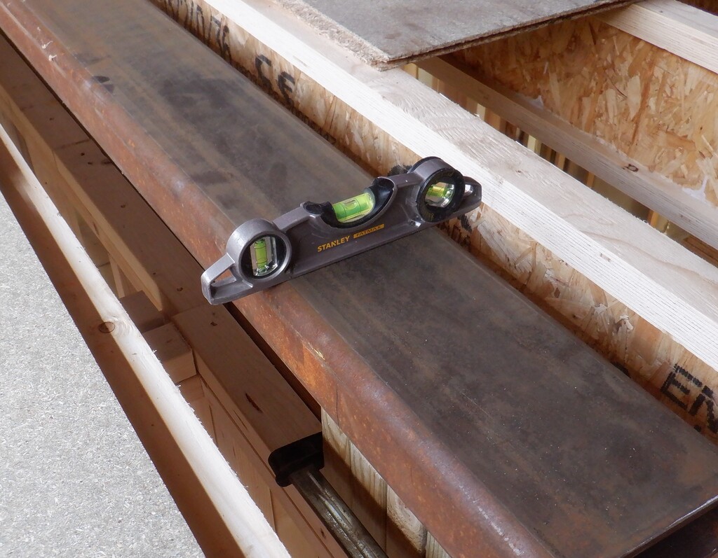
    Water-tank-support-all-level

    Fiddly Hidden Elements Completed in First Floor Joist Space

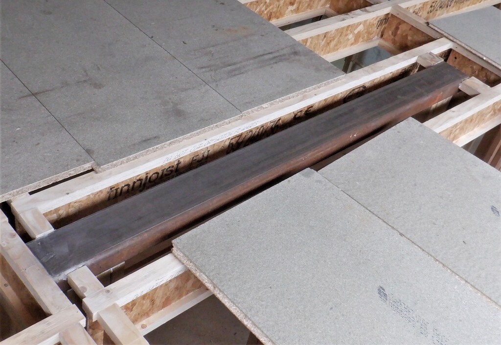
    Water-tank-support-installed


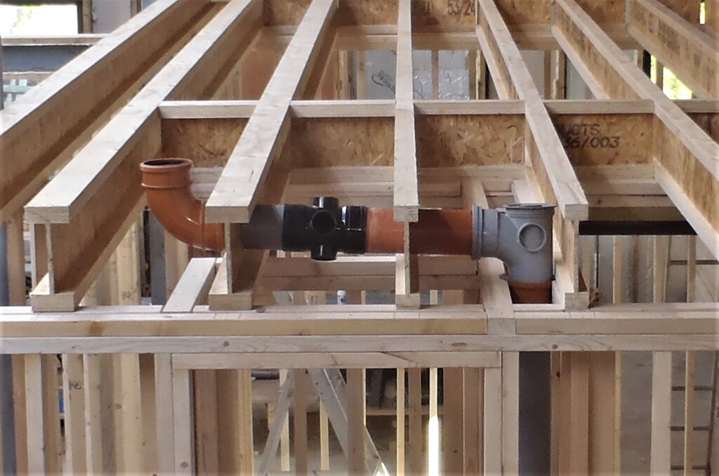
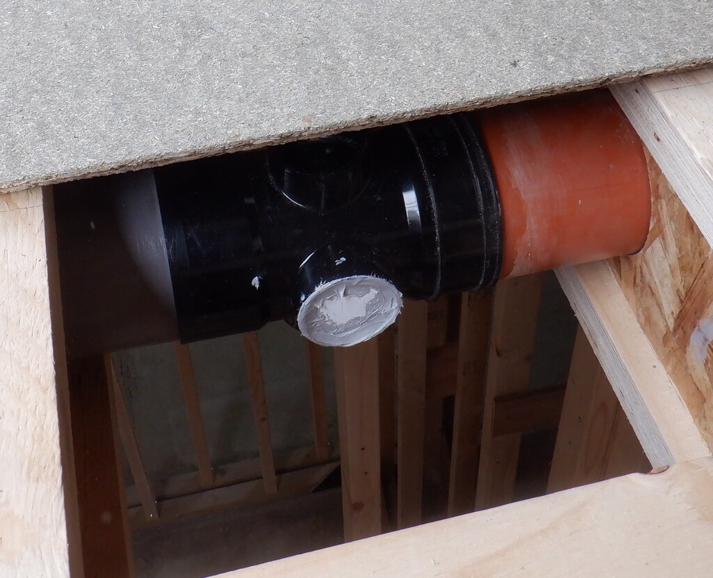
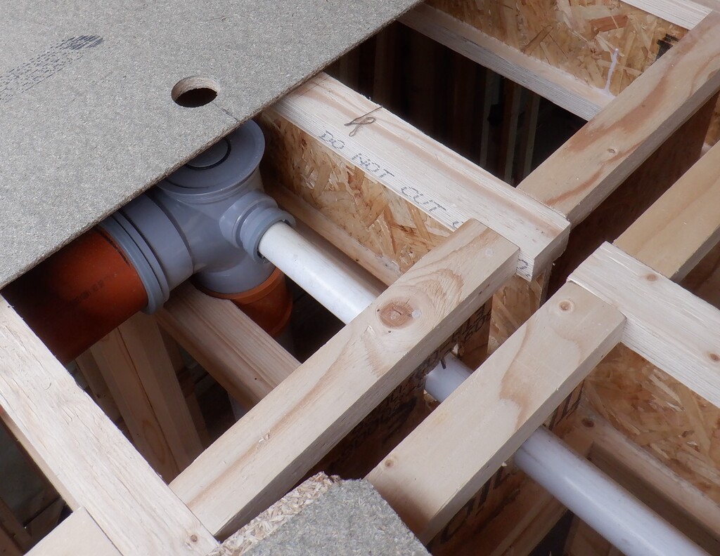
    The next job was to connect a waste water pipe that we will need for the upstairs bathroom’s basin and shower. But we discovered that the boss adapter we had already previously connected together into the large diameter waste pipework was a different size hole and we didn’t have any fittings that would fit reliably. It looked like a 50mm diameter boss socket but it was a case of a different manufacturer and their idea of what standards to adhere to. We tried all sorts of different solutions, rubber adapters and the like but O Boy we failed to get anything to work. So we had to block off the hole by making a circular disc of plastic and use PU sealant to stick this disc into the boss connector and seal it up. We fortunately had the luck to use another pipework piece, a right angle element that had more of these boss connectors but manufactured by someone else so we moved over to use that one instead. we had a particular adapter that fitted very well so we solvent welded the 40mm water pipe diameter adapter into the boss socket, after we had drilled a 40mm hole and then slide in a two and a half metre length of white pipe, ready for further connections to the basin and shower units later on.
    Fiddly Hidden Elements Completed in First Floor Joist Space

    Plugged-up-waste-boss

    Fiddly Hidden Elements Completed in First Floor Joist Space

    Watepipe-for-shower-and-basin


    After all that palaver, we moved over to the front of the house over the Entertainment room to design and build a air ducting channel that fits in between two joists so it can run underneath the upstairs Study room. This air channel is the waste air being collected by all the ground floor rooms at the front of the house like the Kitchen, Entertainment room and the Great Room and the Conservatory too. Normally, our waste air ducting will run on top of the floorboards on the first floor running around inside the triangular void spaces but we didn’t want to have to introduce four sharp bends in the air flow to just avoid crossing the upstairs Study and also have a permanent square boxing running around this room too. So, we routed the air ducting downwards to squeeze in between two joists for a short distance before rising again and heading off to the Utility Room for processing. We used a mixture of 30mm and 35mm thick PU foam boards that has the shiny aluminium paper coated all over them. It is quite smooth so will provide very low air resistance and it has two gentle slopes to avoid the sudden change of direction. The pieces were hooked and glued into place to create a square channel. The rest of it will be done later on when we build the remaining waste air channels.
    Fiddly Hidden Elements Completed in First Floor Joist Space

    Air-duct-over-entertainment-room

    Fiddly Hidden Elements Completed in First Floor Joist Space

    Air-duct-inside


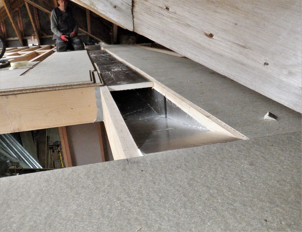
    The final piece of work that we needed to do before the floorboards were laid, cutting off our access to this joist space (because the Entertainment room has the concrete ceiling, cutting off access from below. This was to install the air extraction pipework for the aforementioned Entertainment room. All the extraction pipework will be 100mm metal ducting with metal sweep corner pieces etc. and we connected together one 90degree bend to a short straight piece, then a 45degree bend to raise the ducting above the floorboard and left a short length sticking out. All this is done inside the space between the joists that lined up with the hole we left behind in the concrete block ceiling but we didn’t leave it at that point. We wanted to make sure that any sound waves being generated inside the Entertainment room were dampened and not leak out through the air ducting pipework and infect the Study sitting over the top. To this goal, we built a box out of left over pieces of chipboard floorboard pieces and glued this box down to the concrete surface and laid the metal pipe along inside and glued this in too.
    Fiddly Hidden Elements Completed in First Floor Joist Space

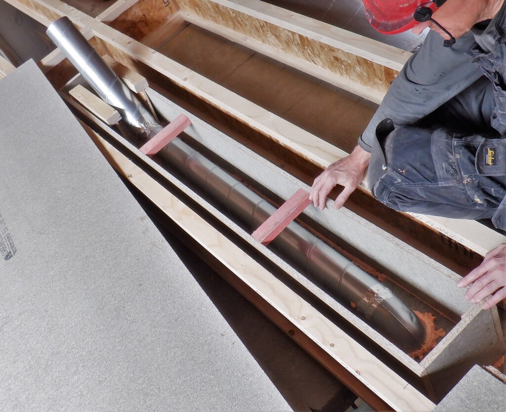
    Sound-resistant-box-for-entertainment-room-duct-installed

    Fiddly Hidden Elements Completed in First Floor Joist Space

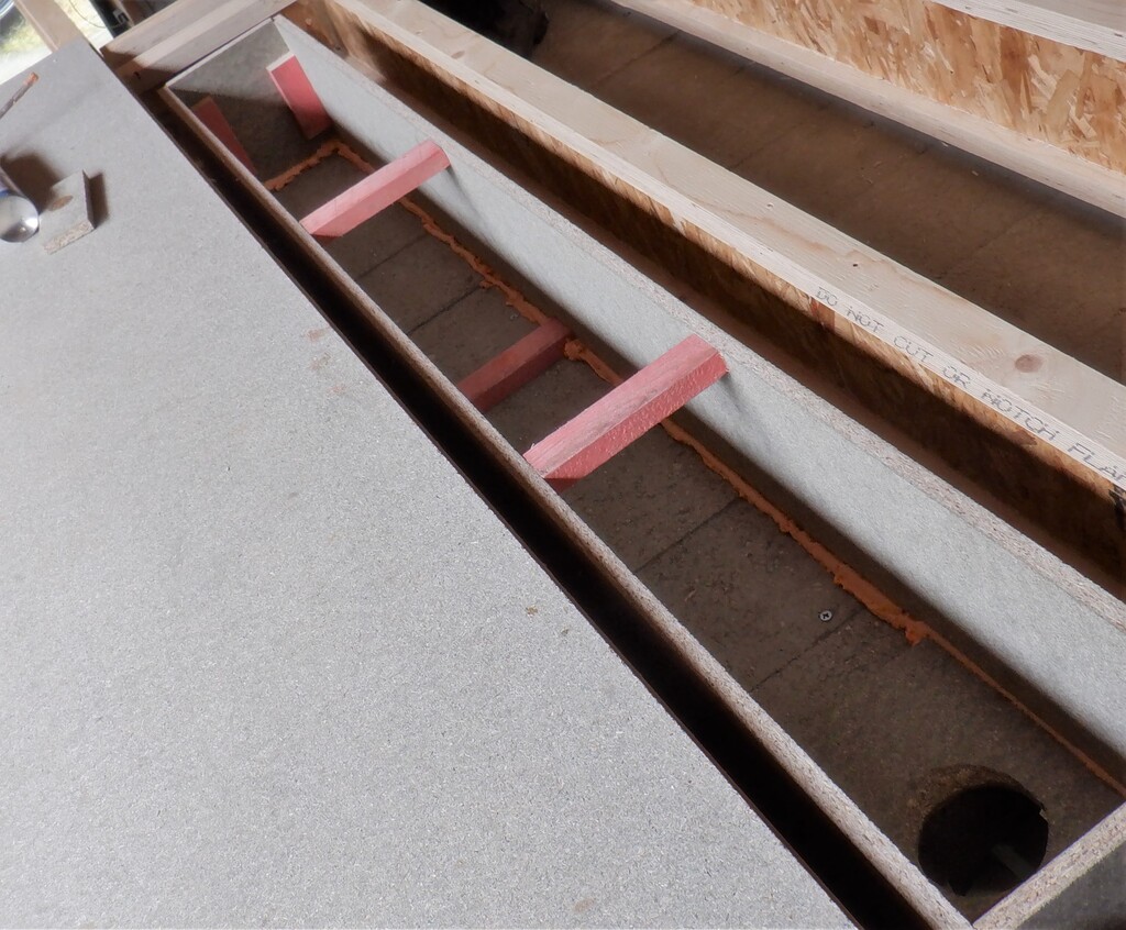
    Sound-resistant-box-for-entertainment-room-glued-in


    We will fill this box up with sand but it needed to be dry first so we filled three trugs full of sand from our sand bank outside our conservatory and spread it all over the kitchen floor to dry off, blowing our giant fan over the top to assist this process.
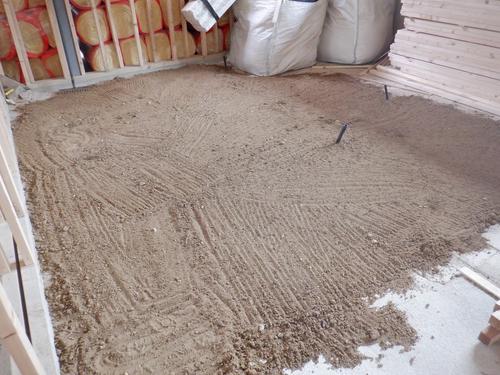
    Fiddly Hidden Elements Completed in First Floor Joist Space

    Drying-sand


    One of the last things we were doing towards the end of the week, was putting more noggings across various collections of joists, some over the Entertainment room, some over Bedroom 3, some over hallway outside the Cloakroom, all to anchor the first floor support joists and stiffen them up.
    By the end of the week, we had done lots of different “little” tasks, had only put down two more rows of floorboards but that building a house for you. There are certain jobs that depends on the completion of other jobs. it is very important to do each one in order .. or else!
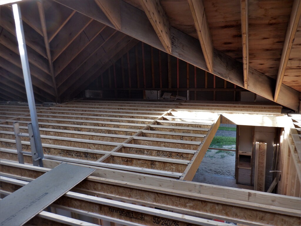
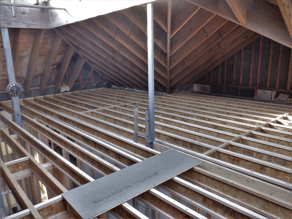
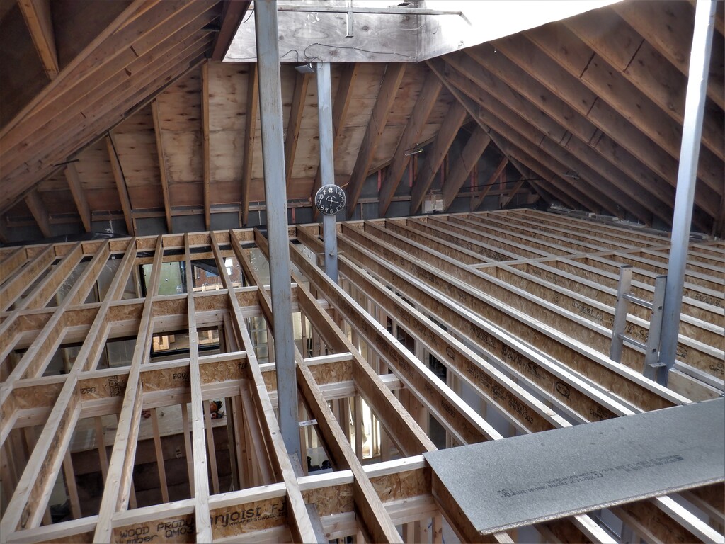
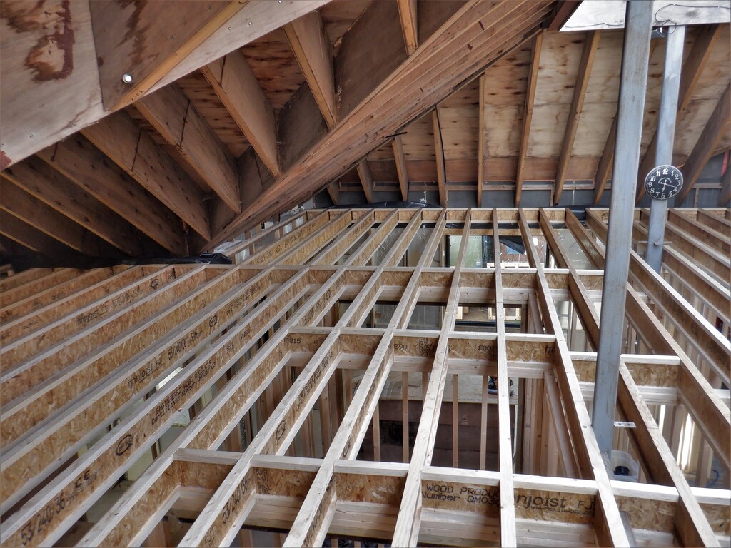
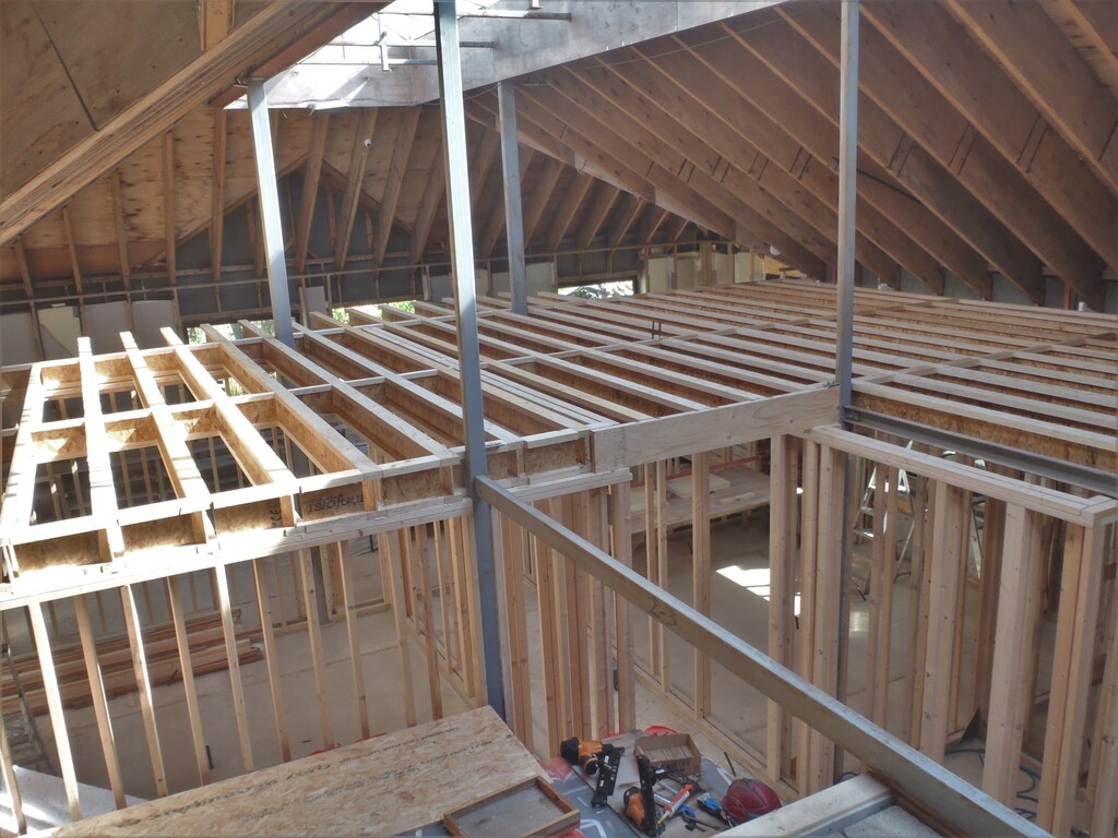
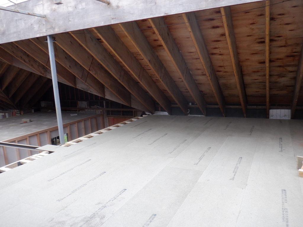
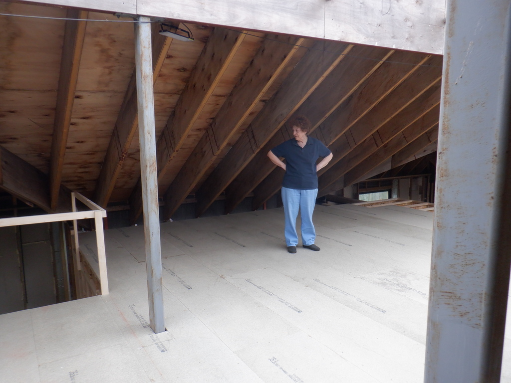
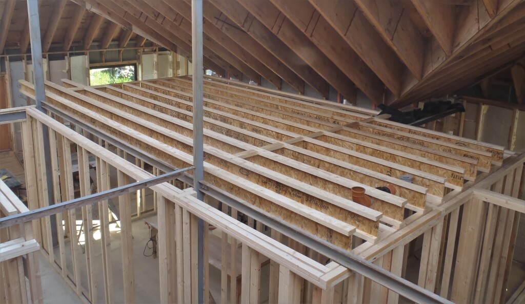
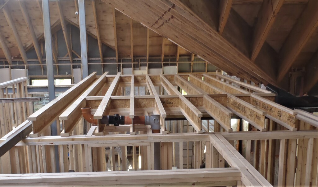
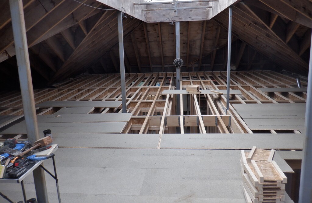
    Here is a picture of our first floor with all the piles of chipboard boards waiting, a table of tools and working area.
    Fiddly Hidden Elements Completed in First Floor Joist Space

    First-floor-end-of-week-3-1

    Fiddly Hidden Elements Completed in First Floor Joist Space

    First-floor-end-of-week-3-2

    Fiddly Hidden Elements Completed in First Floor Joist Space

    First-floor-end-of-week-3-3


    We resume on Monday with these little jobs!! Phew!

  • Sun Shield Patched and Installed over our Corridor plus New Waterproof Cover for Header Tank

    It is very very hot outside today, we had to repair the tarpaulin that provides a sun shield over our long corridor in our temporary living quarter and also replace one of the tensioning ropes.

    Sun Shield Patched and Installed over our Corridor plus New Waterproof Cover for Header Tank

    Sun-corridor-cover-Jun-2021


    The rope had frayed quite badly in the middle point where the whole cover is hoisted up to provide two sloping surfaces to shed the rain water. So we had to thread a new piece of rope through which was a bit fiddly. For the large tear, we found two thin oak strips and while pulling the tear closed, used the two pieces of timber and clamped across the tear using six screws alternatively driven from each side and holding everything together, hopefully for another year or so.
    Sun Shield Patched and Installed over our Corridor plus New Waterproof Cover for Header Tank

    Sun-corridor-Cover-repaired


    Then, we replaced the 10 year old waterproof cover, protecting our header tank that sits on top of our garage to provide a temporary water supply to the kitchen, shower and toilet downstairs. We cut another piece of DPM plastic measuring 2.1metres by 2.7metres long and rewrapped the rectangular structure and re-tied the rope back into place.
    Sun Shield Patched and Installed over our Corridor plus New Waterproof Cover for Header Tank

    Water-tank-recovered


    Next, we had a quick survey of our roof surfaces to make sure that there were no holes or wearing patches that might look troublesome for us in the future and we can report that it is looking good.
    That concludes this year’s annual maintenance for our temporary living quarters.

  • All of the Remaining Joists Up and Secured

    We carried on with the task of cutting and hauling up a whole series of Joists to form our First Floor structure. We had started at the back of the house over Bedroom 3 and its en-suite and worked across the building towards the middle, stopping at the metal Skylight legs. Here we had our very longest joists to put up next, nearly 11metres long, stretching from over the Cloakroom, a hallway, two cupboards and across Bedroom 3 to arrive at the external wall.
    Then, the next task was to replace the C channel metal bar that went between leg 2 and leg 3 of the Skylight, and replaced it with a full sized LVL (it is like plywood but with no twisting of the layers) plank measuring 240mm high and 45mm thick and about 3.7m long. This was bolted back onto the metal legs with 12mm thick high tensile steel bolts and spiked connecting washers to help spread the load bearing forces.

    All of the Remaining Joists Up and Secured

    LVL-bolted-to-leg-bracket


    This beam forms the top end of the staircase and we wanted to make it much easier to mount the various structural elements that makes up the framework around the staircase itself. It has a matching LVL plank running parallel but at the other end of the stair hole, just short of the main wall running along the front of the building that forms the kitchen and great room external walls.
    Then a final piece of LVL plank was fitted between these other LVL pieces and this had eight joist metal brackets nailed at the 400mm spacing as per normal to allow the continuation of the joists going across the Entertainment Room and Utility Room.
    All of the Remaining Joists Up and Secured

    Stair-trimmer-joist-brackets

    All of the Remaining Joists Up and Secured

    Joist-brackets-nailed-to-LVLs


    After that, we carried on with the joists but starting from over the Front door this time and working forward to the metal legs of the skylight which was relatively easy and quick to do.
    All of the Remaining Joists Up and Secured

    Stair-trimmer-with-joists-installed


    This leaves just four more lines of joists to complete, in two sections, going down the hall way past the Entertainment Room towards the Utility and Bedroom 3 rooms and over to the outer wall. A final piece of LVL plank was cut and positioned stretching from the left side of the Tech cupboard to the Entertainment Room to help support the long unsupported span going along this hallway. This LVL plank had four more pairs of joist brackets put on both sides and we did the shorter pieces first, some 3.2 metres and got them installed with the usual glue and nails. We then cut the final four longer pieces, some 7.53metres long and instead of installing them into place, we hauled them up to the first floor and left them out of the way.
    All of the Remaining Joists Up and Secured

    Joists-over-the-hall


    This meant that we could finally finish off building the last few walls and doorways near the Utility Room. We had deliberately left this undone in May because we knew the task of bringing in these long Joists, would need the angles while approaching in from the side door and get pieces ranging from six metres up to eleven metres in, up and landed on the First Floor area and moved around the house as appropriate.
    It will feel quite strange to having to leave the Utility Room through a proper doorway now.
    We didn’t quite have enough time to properly glue and nail down the last four joists but they are in place now so we can safely say “We have Done all the Joists and All Fitted!!”
    All of the Remaining Joists Up and Secured

    All-joists-installed-1

    All of the Remaining Joists Up and Secured

    All-joists-installed-2

    All of the Remaining Joists Up and Secured

    All-joists-installed-3

    All of the Remaining Joists Up and Secured

    All-joists-installed-4

    All of the Remaining Joists Up and Secured

    All-joists-installed-5


    But this is still not the end, we have to put in dozens of noggings in the middle of longer spans on all the I-Beams to help stiffen them against twisting and then put down some 120 sheets of floorboard, Phew!

  • The Two Defective Windows Replaced and Third Polished

    Today, Tuesday the 8th of June, saw the arrival of two replacement triple glazing units, to swop out the defective windows. They had internal scratches between the layers of glass panes so it must have been caused during manufacturing processes, but a third window had a scratch on the outer surface and the glass people declined to swop that one out but on the other hand, did provide a small pot of glass polishing powder instead for us to polish the scratch away.
    But before we could do any of this exchanging lark, we had to, on the previous day, work slowly and carefully to remove the oak beadings, four of them for each window and then unscrew the plastic brackets holding the glass unit in place. Next, we cut the security tape behind the glass and with the help of our neighbour and four large handles with suction cups managed to haul and man handle the very very heavy 117.93kg window (we found the weight on a label stuck on the edge of the unit!) and carefully got it onto our medium sized flat bed trolley we had adapted (again) to help hold and transport the glazing unit.

    The Two Defective Windows Replaced and Third Polished

    Old-windows-removed


    We got the two units collected together near the driveway, ready for the van’s arrival.
    Finally, we spent several more hours cleaning the glue and the remains of the tape off the metal frame and got it all clean. We stuck on a fresh line of double sided sticky security tape ready to pull off the wax protective strip when we are about to put in the new Glass on the morrow.

    So this brings us to today, when the van arrived just after 9am (scheduled for after 10am) and we hastily got our worksuits on, grabbed our neighbour again and got the two new glazing units off the van, parked on up against the wall on a pallet and then loaded the old ones back into the van for them to take away and one assume that they will analyse the glass panes for their mistakes back at the factory.
    Finally, we moved each of the new units to their window holes, reversing the process, with lots of grunts and managed to slip them home and stick them back onto the uncovered security tape. We secured all the plastic brackets back into place again and reattached the Oak beadings back on.

    The Two Defective Windows Replaced and Third Polished

    H-window-Replaced

    The Two Defective Windows Replaced and Third Polished

    Great-room-window-replaced


    The third window with the scratch on the outside (we don’t thick we scratched it) we did after lunch.
    Window-C-Scratch-From-inside

    Window-C-Scratch-From-inside


    We made a thick creamy paste of the cerium oxide polishing powder and dabbed the mixture onto a pre-soaked cloth wheel, fitted it to our electric drill and carefully buffed the scratch for about 30 minutes in total, stopping many times to spray the glass with water to cool the temperature down as much as possible, to avoid creating heat stresses and shattering the glass. We can’t show you the result because it’s not visible (grin)…

    So this draws to the conclusion of our windows story, stretching back to last October, just over seven months ago when it all first started!! It got dragged out because of the Covid Saga! Phew!

  • Third of First Floor Joists and Floorboards Built

    We carried on from last week in installing the joists for the First Floor. We glued and nailed the section over Bedroom 1 and then moved on to tackle the section over the Kitchen and the Hall in between these two rooms. Before we did the Hallway, we cut a chunk off the LVL solid timber piece, some 1770mm long that bridged over the Hallway to support the wide flange I-Beams coming from the Gallery. These were held up using rated joists hangers, fixed into place using hardened thick nails.

    Then the last bit of work to do in this section, was to install extra noggins half way down the joists to help stabilise and stiffen up the wiggly I-Beams.

    Third of First Floor Joists and Floorboards Built

    1st-Third-of-joists-installed


    All this just took only another two and a half days and we decided to have a change of order. Instead of carrying on installing more joists, we opened up our pack of 18mm thick chipboard floorboards that have tongue and grooves machined on all four edges to make joining together the floorboards very easy and form very strong overlapping floor. We loaded up on our trolley 40 sheets, each measuring 240mm long by 600mm wide and weighing about 12kg each. We estimated that we would need forty sheets to build the flooring for this first section and the Gallery and we trundled the lots around to the Conservatory entrance in our Great Room and moved the pile into the house. The first job was to snap a chalk line 500mm from the edge of the First Floor looking over the Great Room so our first line of the chipboard sheets would overhang and we can slice off the tongue at the later date to have a clean cut edge. This first line also included the two metal posts that supports the Skylight so we had to cut a small piece out of the board, the cut being centred on two neighbouring joists and then cut out the shape and size of the metal leg itself (160mm by 80mm). Then we doubled checked the alignment of the completed line before we glued and screwed down these four and a bit sheets. Then over the next day and a half, we got all the rest of the boards glued and nailed down, remembering to keep any cut-offs piece bigger than two joists to ensure that any floorboard is fully supported on at least two joists.

    We stopped half a row short of the staircase so we could carry on installing more joists and have the floorboards coverage continue with all the tongue and grooves still locking the boards together when we resume that task.

    Third of First Floor Joists and Floorboards Built

    1st-Third-of-the-floor-laid-1

    Third of First Floor Joists and Floorboards Built

    1st-Third-of-the-floor-laid-2

    Third of First Floor Joists and Floorboards Built

    1st-Third-of-the-floor-laid-3

    Third of First Floor Joists and Floorboards Built

    1st-Third-of-the-floor-laid-4


    To finish off the week’s work, we put up six more joists (almost 7metres long) going over Bedroom 2 and its en-suite which were also glued and nailed into place. We got as far as slicing five out of a further nine more joists measuring 9metres long and they are laying up on the first floor waiting for next week.

  • Started Installing Joists for First Floor

    We have started the process of installing the joists for the First Floor. The last two and half days were spent on several tasks, like for example, marking out on top of all the structural walls running from the front to back of the house, with 400mm centres for each joist. We used our new green laser line generator to produce lovely straight alignments right across the whole building and then using this reference line to mark off all the 400mm centres on each wall supporting a joist.
    Next we set up the saw station outside under our front porch, the only place where we had enough room to accommodate eleven metres of I-Beams and kept as dry as possible between sessions. Then put on an extension fence on two further trestles and additional roller support stands further out along the line in and out of the saw station.

    Started Installing Joists for First Floor

    Joist-cutting-setup

    Started Installing Joists for First Floor

    Joist-plan


    Then, the real work starts, we decided to start from the Great Room end of the house over Bedroom 1, we measured the distance from the Bedroom 1 wall interfacing with the Great Room, to the wall flanking the little hallway to Bedroom 2. This revealed that it was 6840mm for the first six joists, labelled 24 through to 19, arriving on the first of the twin 63mm think walls and these joist are the 53mm width flanges as they don’t have to deal with the Gallery sticking out the Great Room. Joist 18, the first of the 96mm flanges is a full 8metres long and then joist 17 and 16, also 96mm flanges were sliced at 8300mm long. The saw station worked very well, with only a slight adjustment needed to increase the spacing to allow the wider flanges into the station.
    Started Installing Joists for First Floor

    Sawing-a-96mm-joist


    We carried each one across our driveway and then into our Side door, along the hallway and then sliding (just!) into Bedroom 1’s entrance, to climb up the stepladder and hoist the joist up on top of the Great Room wall and rotating around a bit before climbing up the second stepladder to dump the other end up on the En-Suite wall and finally pulled back until it reached the mini hallway. We collected the joist in a group over near the outside wall because there was a special requirement of making a 110mm diameter hole through the webbing of Joist 18 and Joist 19 to allow the sewage pipework to run from the upstairs toilet shower room. This is a rigid piece of pipework and the joists had to be free to move to allow this insertion to occur (while the other joists were out of the way).
    Started Installing Joists for First Floor

    Plumbing-for-the-upstairs-Toilet


    Using the left-over pieces of the I-Beams, we created a pile of noggings either measuring 347mm or 304mm wide plus a few specials measuring 325mm that fits in between a wide flange and a narrow flange joist. These noggings fills in the spacing between the joists to help anchor and stiffen up the whole joist structure to stop them slipping sideways and falling over under load.
    For the end of this week, we put in a set of noggings and spaced out the joists evenly, for a test run and see how well things look. We didn’t have time to glue or nail them down.
    Started Installing Joists for First Floor

    First-set-of-joists-placed-1

    First-set-of-joists-placed-2

    First-set-of-joists-placed-2


    So we will resume next week and start fixing things down properly and so the First Floor is finally being created – Yippee!

  • Wall and Sign Repaired

    This morning and yesterday were spent on repairing the broken wall and repainting the street sign for our Loke after the delivery lorry with our I-Beams had misjudged things and knocked into the curved brick wall at the entrance of our Loke on the main road.
    Yesterday, we managed to pick up the pieces and glue them back together again using our adhesive PU foam that was specialised to glue building materials. Many bricks were still mortared together in large sections and we carefully put the jigsaw puzzle back in the correct order without having to remove any of the old mortar. The bricks were the ones where it had two large round holes instead of a frog and we slid and wiggled each layer back and stick on the top row back down.

    Wall and Sign Repaired

    Rebuilt-wall


    The old metal street sign had also got disturbed and was in terrible state so we decided to bring that home to give it a complete revamp with fresh metal paint.

    Wall and Sign Repaired

    Old-loke-sign

    We removed the old green vinyl coating, scrubbed and got the aluminium clean and shiny again. This then had a half a dozen thin coats of a green hammer effect metal spray paint and left to dry and cure overnight.
    The new letters, “Smiths Loke” was re-created on the computer, using the British Highways standard font face and adjusted to fit along a metre length of the sign and 150mm high with a white border. The paper print out was stuck to the freshly painted metal with that special spray glue that allows the removal and refixing. Then the border and each letter was very carefully cut by following the lines using a sharp scalpel to leave “holes” where the letters were, ready for several coats of a white metal spray paint.

    Wall and Sign Repaired

    Repainted-sign


    Once this was dry, after lunch today, we took up the new sign and positioning it very slightly higher because the old holes had many missing mortar where the plugs were. Drilling new holes and using mushroom headed stainless steel screws, the new sign was affixed back on the repaired wall.
    Wall and Sign Repaired

    Wall-all-refurbished


    We probably will take down the twin street sign on the opposite side of the Loke and do the same thing again. This sign is starting to peel and it is done at a different time and by a different hand with poor quality letter placement so it would be good to get this sign repaired too and both become a matched pair.

    Wall and Sign Repaired

    Old-loke-sign-Left

  • I-Beams Arrive!

    In the morning we prepared an area to store the beams next to the house.

    The lorry arrived at 1:25pm with the 66 special I-Beams on a open flatbed vehicle, in two packs covered in plastic. The driver thought he could reverse down our Loke and save a lot of effort but after attempting to come in both directions and failed to get enough room to straighten up. In fact, he couldn’t hear the shout to stop and unfortunately bumped into the garden wall of the house flanking the entrance to the Loke and knocked a section down. We excused the driver and we said that we would repair the wall ourselves (we confessed to the house owner who is a nice chap).
    So the lorry parked straight on the main road and we unloaded the I-Beams one by one off the back and placed them into the Loke to minimise the unloading time and then let the driver go off.
    It was 2:50pm at this point, so we had a half an hour rest plus to quench our thirst too!
    Resuming at 3:30pm, we got our trolley loaded up with 22 pieces and started down the Loke. But soon discovered that the dolly module was struggling to get over the little ramp and was creaking and wiggling alarmingly. We put on four more giant clamps to help stiffen up the load points and carefully got over the ramp.
    That was exactly a third of the total and it was clearly overloading things. So we reduced the quantity and put only 15 pieces for the next three trips. The ratchet straps were doing a good job of keeping everything tied down and stopping the load slipping.
    Once we got the load down to our place, we transferred it over to our temporary storage location just inside the fence (we released the wire mesh and rolled it up and pulled out two posts) and place each I-Beams into an ordered piles on two 2by6 planks supported by two concrete blocks.
    After unloading the final 15 I-Beams, we covered it all up with a fresh tarpaulin as the material they supplied was ripped rather badly during the unloading process.

    I-Beams Arrive!

    All-66-beams

    I-Beams Arrive!

    Beams-wrapped-up


    We finished everything at 7:30pm and we were knackered!!

  • Preparing for the Arrival of 66 Timber I-Beams

    Monday is the big day with the arrival of 66 special timber I-Beams, the last three days have been spent preparing for this happy day. So, we adapted our large flat bed trolley to help the job of transferring the very long I-Beams down the Loke from the main road. They come in a range of lengths, the majority being ten metres long but several are eleven metres, some 35feet and weighing up to 66kg each!
    The trolley had a single upright plank mounted on, with a small gap underneath to allow for a ratchet strap to lock down the jumble of I-Beams tight to the trolley when we haul it down the Loke. We estimate that it will take three separate trips to move all the 68 pieces, the total weight being over two tons so we decided to split it into three separate loads.

    Preparing for the Arrival of 66 Timber I-Beams

    Beam-transport-trolley


    Next, we made a little dolly module to help support the other end of the long beams. This module is using two solid castors bolted to another one of our old trusty two by six planks and an extension tower built upwards to bring the level to match the main trolley.
    Preparing for the Arrival of 66 Timber I-Beams

    Beam-transport-dolley


    Because we were on the main road, which is quite busy, we made two alert signs using a couple of our trestles and clamped on to the front face a shiny insulation board with yellow and black stripe tape around the border to divert the traffic away from our Loke entrance to allow us to swing in these massive lengthy objects, walking into the road itself when we take them off the lorry.
    Preparing for the Arrival of 66 Timber I-Beams

    Traffic-blocking-board


    Also during this last week, we constructed a new slicing machine, see Extra Large Sliding Saw and repaired one of the tyres on the large trolley that had developed a leaky valve and we replaced the inner tube. It was a quick leak and we wanted to ensure that the trolley stood up to giving us the proper quality of work without having to pump up the tyre every 10 minutes.

  • Extra Large Sliding Saw

    The other piece of equipment we made while we waited for this day, was to build a special chop saw table to cope with slicing these I-Beams. Their physical size, especially the biggest one is 96mm wide (the flanges) and 240mm high. No standard chop saw, or even mobile saws, have enough depth of cut to cope with that kind of magnitude so we pulled out an old piece of equipment we had made several years ago (see
    Bevel Slicing Machine Repaired
    back in November 2017) and adapted it for our new task. The base board and hinge was removed and a new fixed plate mounted and then two double extension drawer runners were screwed on. Then, one of our old trestle tables was used to build a framework to allow the I-Beams to slide through this module against a straight and square fence. The saw part was then connected to the support table and we now have a smooth sliding saw ready to slice up our I-Beams into the required lengths.

    Extra Large Sliding Saw

    Cross-cut-saw-for-Joists-1

    Extra Large Sliding Saw

    Cross-cut-saw-for-Joists-2

    Extra Large Sliding Saw

    Cross-cut-saw-for-Joists-3


    Next is to prepare the trolley to help transport these I-Beams down our Loke.