We needed to make a start on this first part of the ducting because it is a big object, occupying quite a significant volume inside the Utility Cupboard and we had to make sure that we had designed and mapped out the path of the ducting going up the wall and diagonally across to the heat exchanger at the top of the cupboard. Then, this would allow us to assemble and install the Cold Water pump and Pressure Vessel, which are major large pieces of equipment, alongside the ducting.
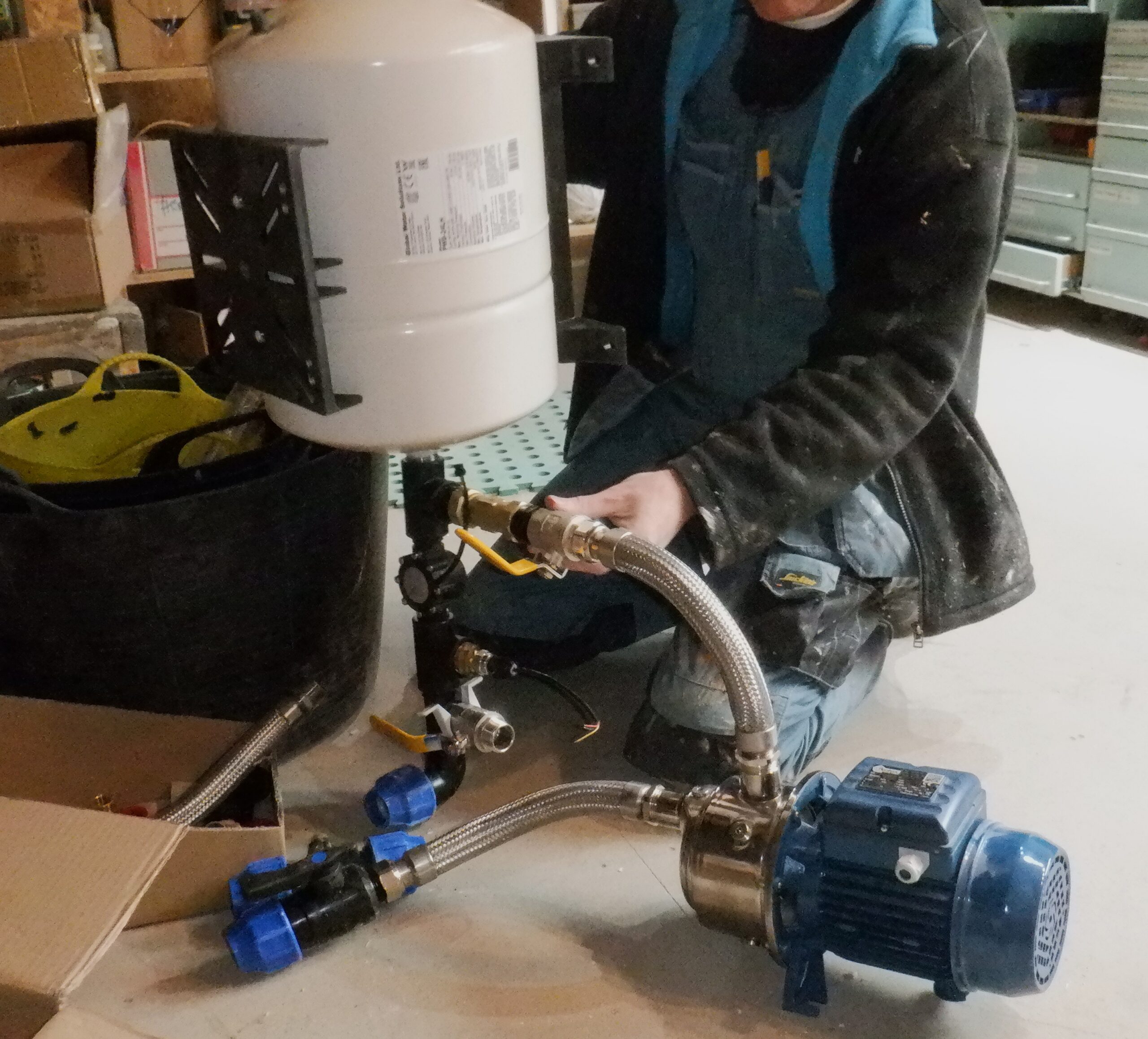
Trying out cold water pressurisation parts
We made use of four little pieces of battens to screw together the four sides of this box, the front and back pieces were cut to form like shape of the letter T so it hooks over the concrete and two smaller pieces that were screwed in those wooden battens.
We use grey PU sealant to both stick this socket into the floor and seal all the way around the four sides and the joint to the concrete floor, plus also put in flashing tape inside to provide a secondary seal and a smoother transition for the incoming air as well.
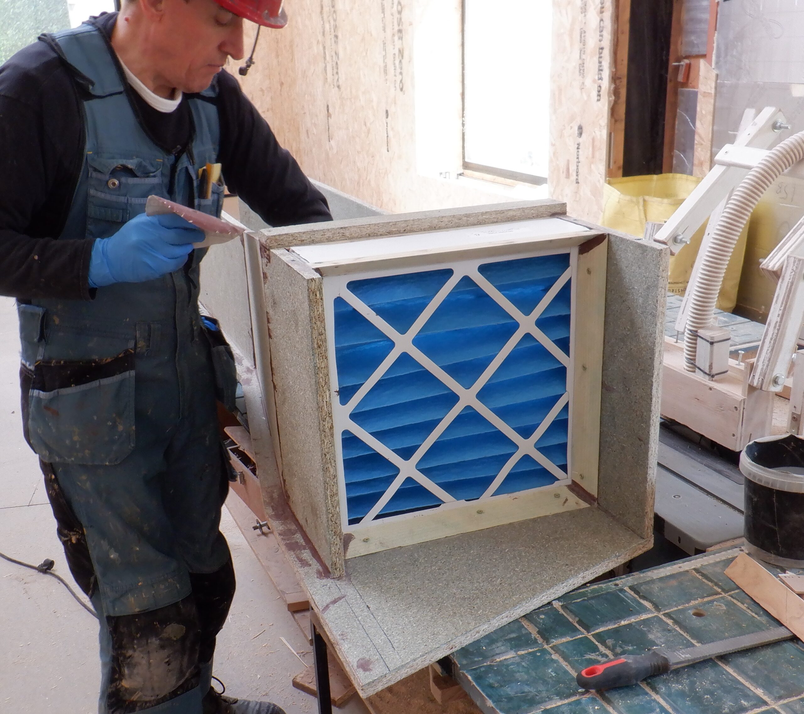
We decided that it would be much easier if we had a single continuous back panel, to map out the path for our ducting. We need to give it a slight angle, approximately 18degrees leaning rightwards, so it can reach the start (or the end) of the heat exchanger. We also need to expand the width and height of the ducting so we can accommodate the fine mesh filter module we are using to collect a lot of the atmosphere dust and other particles floating in the air. So, it was much easier to draw out what we needed directly onto a sheet of chipboard floorboard, including an “kink” elbow at the bottom for the angle change, a straight section and then the expanding section. We drew several pencil line drawings, using a piece of sandpaper to rub out the incorrect lines and settled on a good design. The first part is the continuation of the 290mm square ducting, with 18mm thick walls. The second part is where it expands to accommodate the standard 400mm dust filter which needs to be able to slide in and out, to be replaced with a clean one every now and again. So, we glued and screwed a double set of sloping battens, to form a “housing” to take the folded cardboard filter module, which measures 395mm square by 100mm thick. That is how big this “slot” is, and also, this is how tall the air duct is at this point. It will go flat from now on, and enter into the Heat Exchanger module.
We wanted an extra flange piece sticking out on the side of the ducting so we have somewhere to screw the whole thing up on the wall when it is all fully assembled. So, we proceeded to cut away the surrounding excess materials away, to leave a long “funny” shaped behind, ready for a quick test!
We took this “template” to the Utility Cupboard and slid it flat on the wall and down on to the cement socket we had previously made. We realised that we need to screw a small piece of batten on the wall, to align with the other wooden battens so it can support this back panel. It looks good so we carried on in constructing the rest of the ducting.
The next job was to put on the two side walls, measuring 290mm high for the first section. We needed two short pieces to create the “elbow” kink of about 18degrees change of direction, which then led on to a single straight piece on the left hand side, going all the way up to the heat exchanger, with the height being adjusted slowly rising to a height of 395mm at the filter section. The slope was 690mm long. The other side, the right hand side, was made up in separate pieces so that the width of the ducting could expand to also the 395mm mark. We glued and screwed these set of vertical walls into place. The last section is constructing the filter so that we could have a removable lid to grab the filter cartridge and pull it out. We mitred some left-over angled pieces of timber, to form a “pocket” for the filter and that got glued and screwed into place as well.
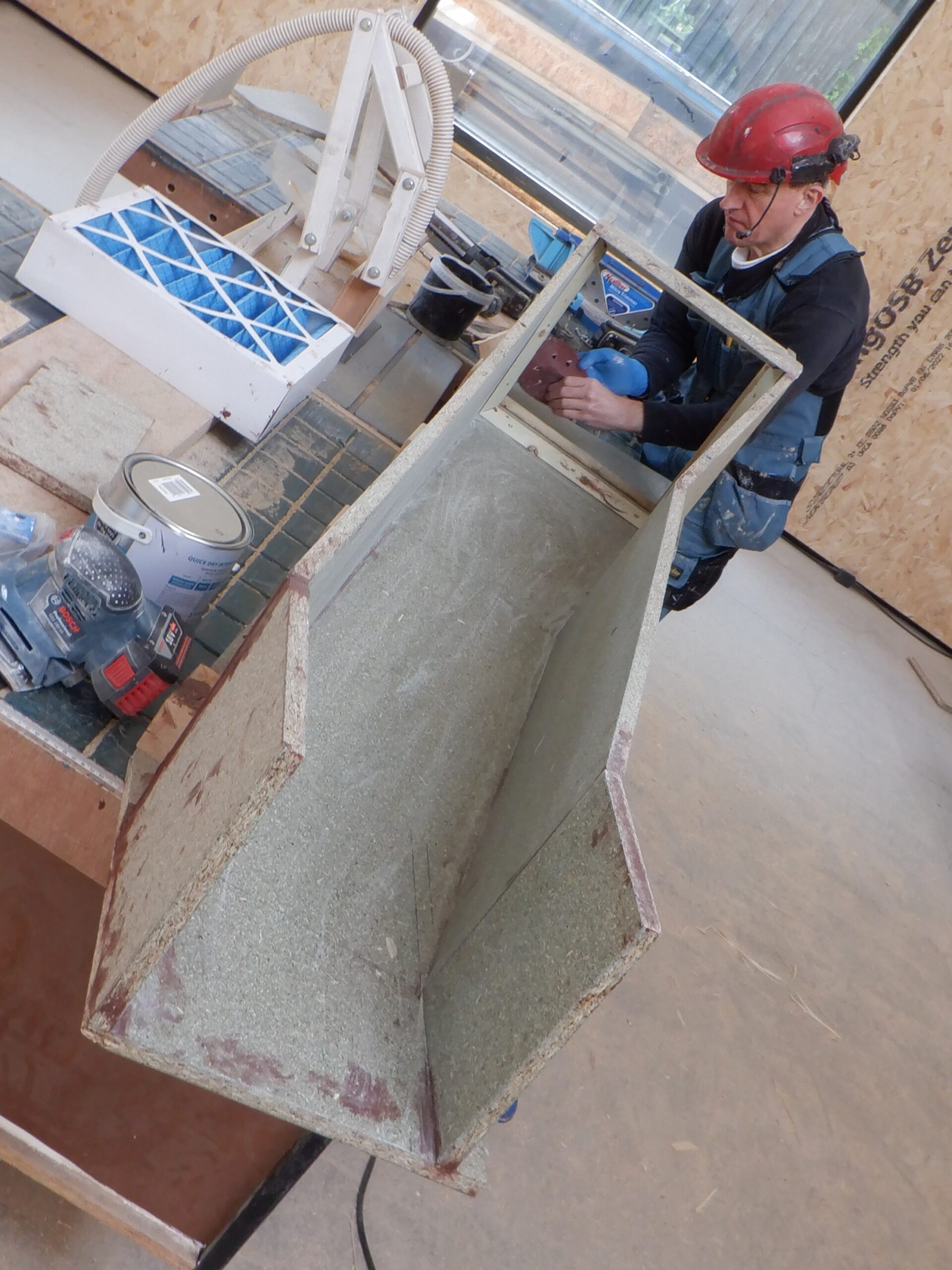
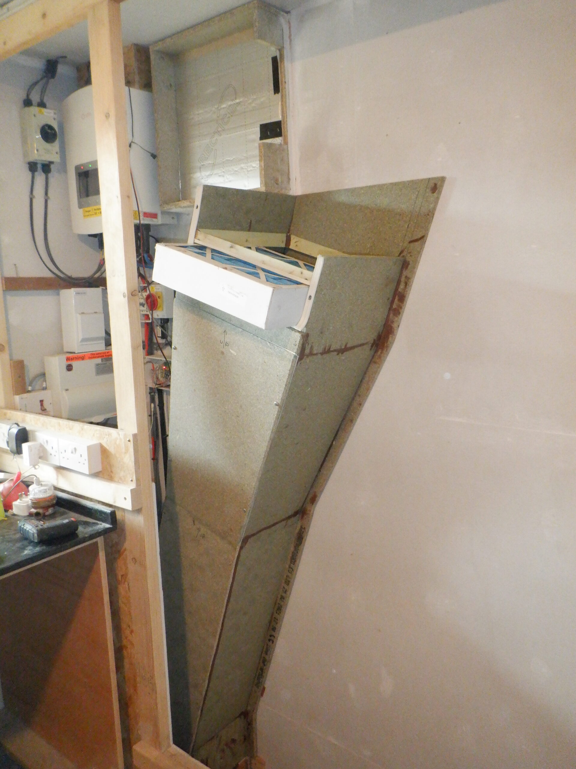
First Air duct being made 1
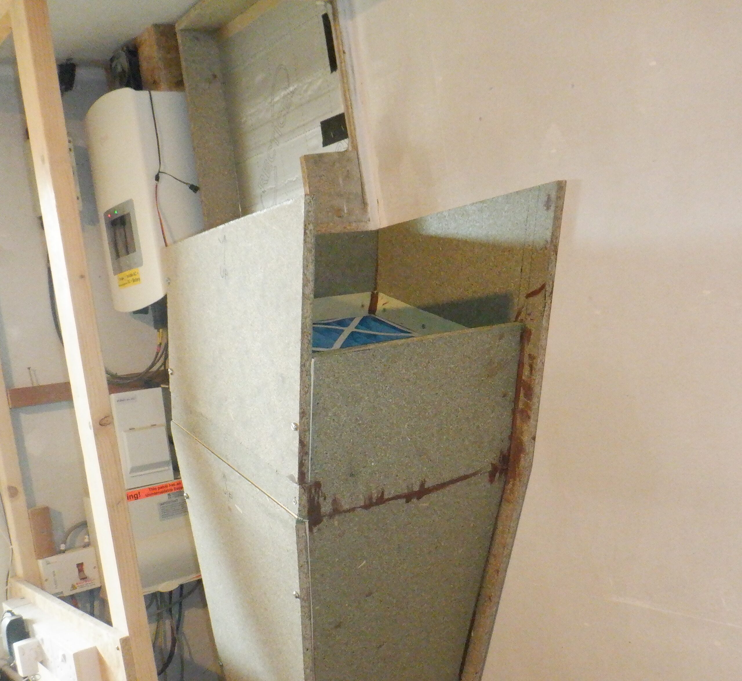
First Air duct being made 2
At this stage, we took the assembled Air Duct back down to the Utility Room and did another test fit, making sure that the bottom section fitted over the socket. Again, all is looking good so it was the final job of constructing the lids. The first section will be glued and screwed permanently down but we wanted the slope section removable so that we could gain access to the internal surfaces, just in case, we needed to clean it out or something. We angled the two narrow ends with slopes so that it will squash down when it is bolted. The bolts were 6mm metal machine screws, going into captive nuts that had been screwed into the top of the side walls. We repeated this method for the lid going over our filter which also covers the entrance to the by-pass channel (underneath the Heat Exchanger) when there is too much heat in the waste air coming out of the house.
Finally, we put on three coats of clear varnish to seal the wood against any moisture coming in from the outside. All our ducting will be protected so that the wood will not get damp and create problems later on.
The first two layers were put on using a roller but realised that this produced a very rough surface so we sanded it a bit smoother and put on a final third coat with a brush instead.
Then, we put on strips of foam rubber draught excluder, around the edges of the section where we got our removable lids.
The last job was to haul it to the Utility Room and its cupboard, and install it into position and screw it down tight. We had left off the bottom portion of the lid so we could reach inside and seal the wooden part of the ducting to the cement square socket at the bottom. Then we glued and screwed that lid on. We also put on the removable lids and put in the air filter cartridge in as well.
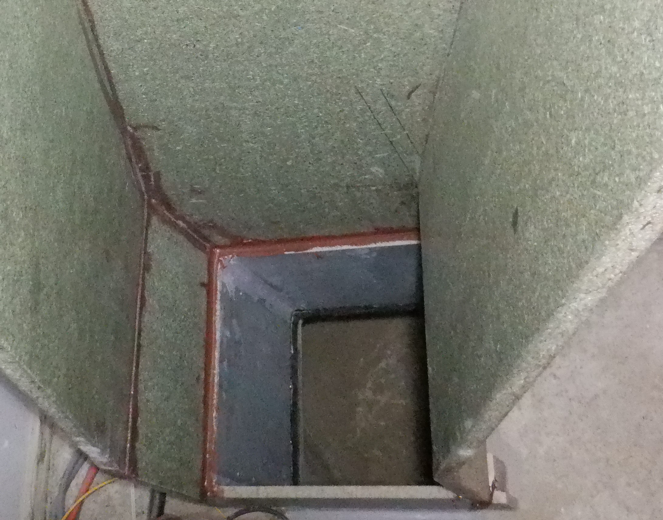
Duct connected to underground Earth Tubes
Fisrt Air con duct in place with Filter
Duct will connect to the heat exhanger
In fact, we thought that it would be a good idea to put a plastic bag around the air filter cartridge so that any building dust and dirt we may generate, wouldn’t fall back onto the filter etc.
That concludes the first stage of constructing the Air Ducting for our Ventilation System. There will be more to report on when we get on with the next stage.
This completed job now allows us to proceed to assemble our Cold Water system with the pump and measuring equipment.
Leave a Reply
You must be logged in to post a comment.