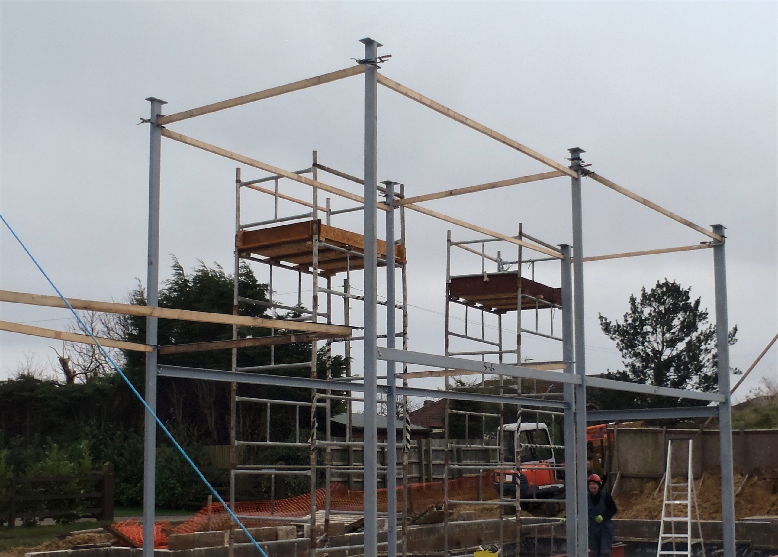
In a very nice bath of warm sunshine, we started this morning with the task of lifting up the first of our huge steel I beams. We got our two towers in place around Leg 1 and Leg 2 and then hauled and wiggled the tall crane wooden legs into position at the outer ends of the I beam. Then installed the two hoist machine up on top of the cranes and lowered the wire and hook down.
The I beam weigh 420kg so each hoist is lifting 210kg which is well within its advertised limit of 250kg! This steel I beam is 300mm high by 140mm wide (the flanges are 8mm thick) and the webbing is 6mm thick and the length is 7535 mm long!!
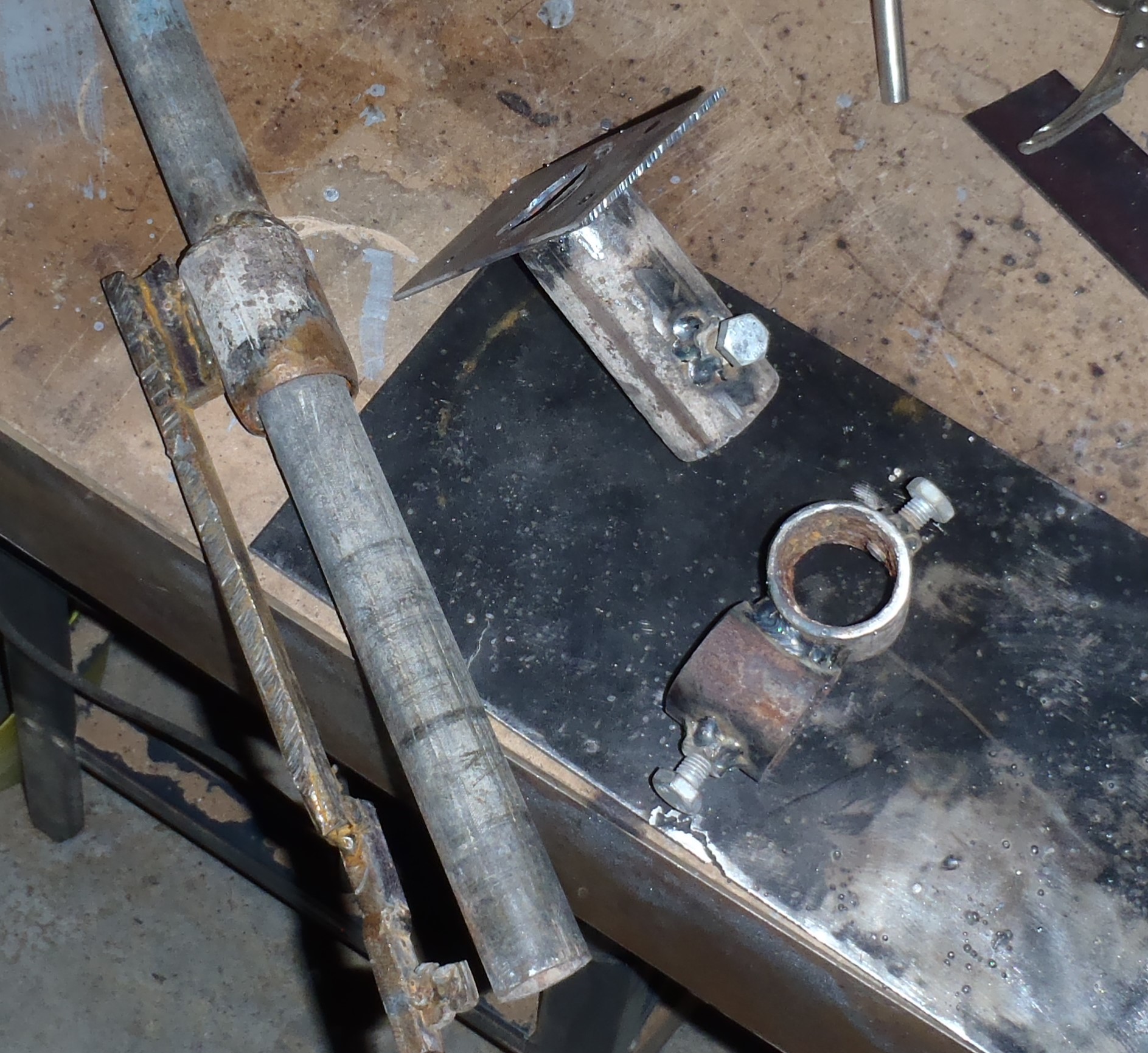
We also attached pieces of soft geotextile material, folded up several times over and put it on the edge of the flange where it would run up against the legs during the lifting stage, thus avoid scratching off the protective paint. Secondly, we attached some split plastic pipes (4 inches long of standard water 22mm pipe) and put them on the edge of the bottom flange where the thick rope is tied around to make sure the sharp edge of the flange won’t cut into the rope when the rope is under the maximum strain.
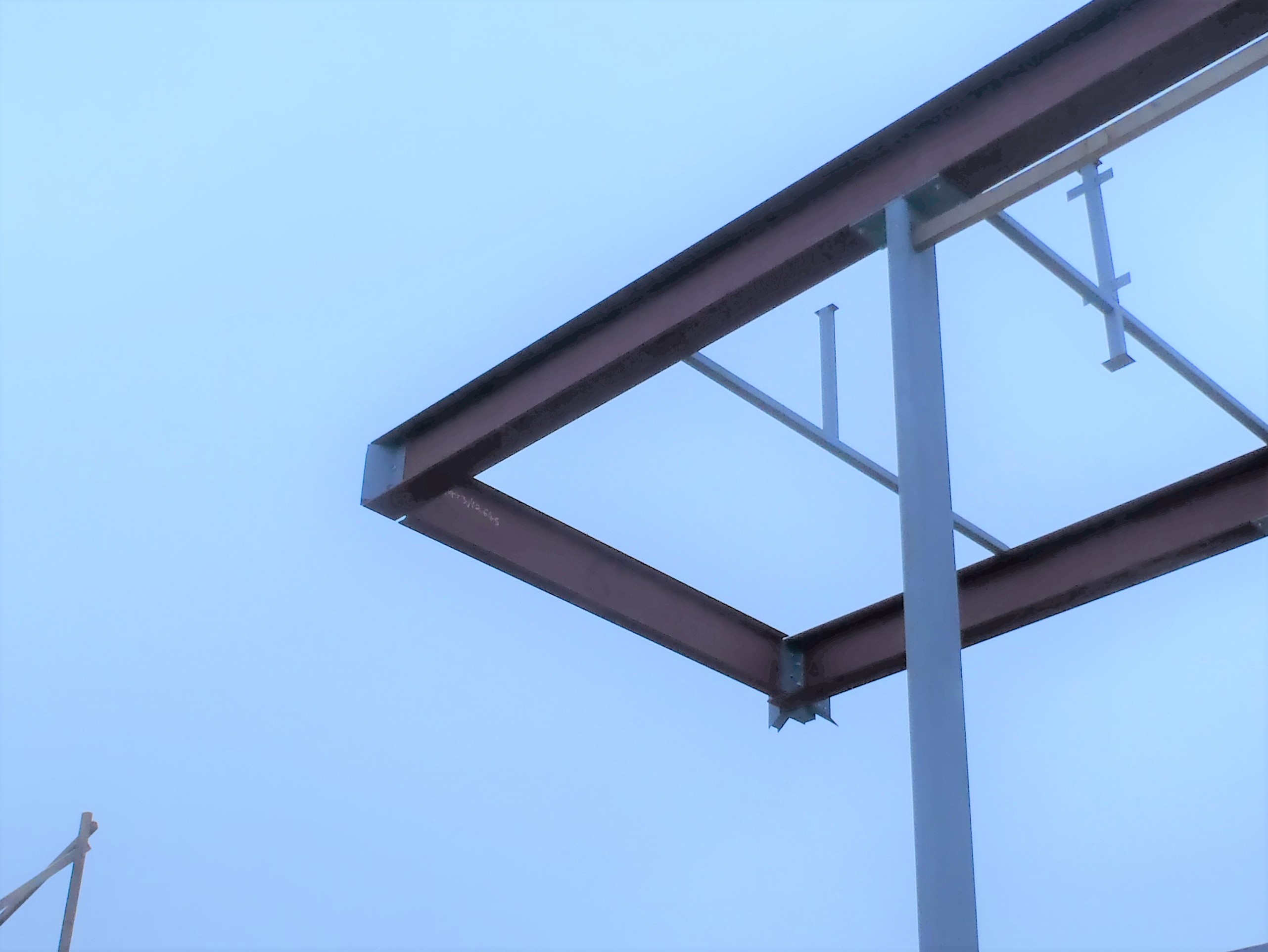
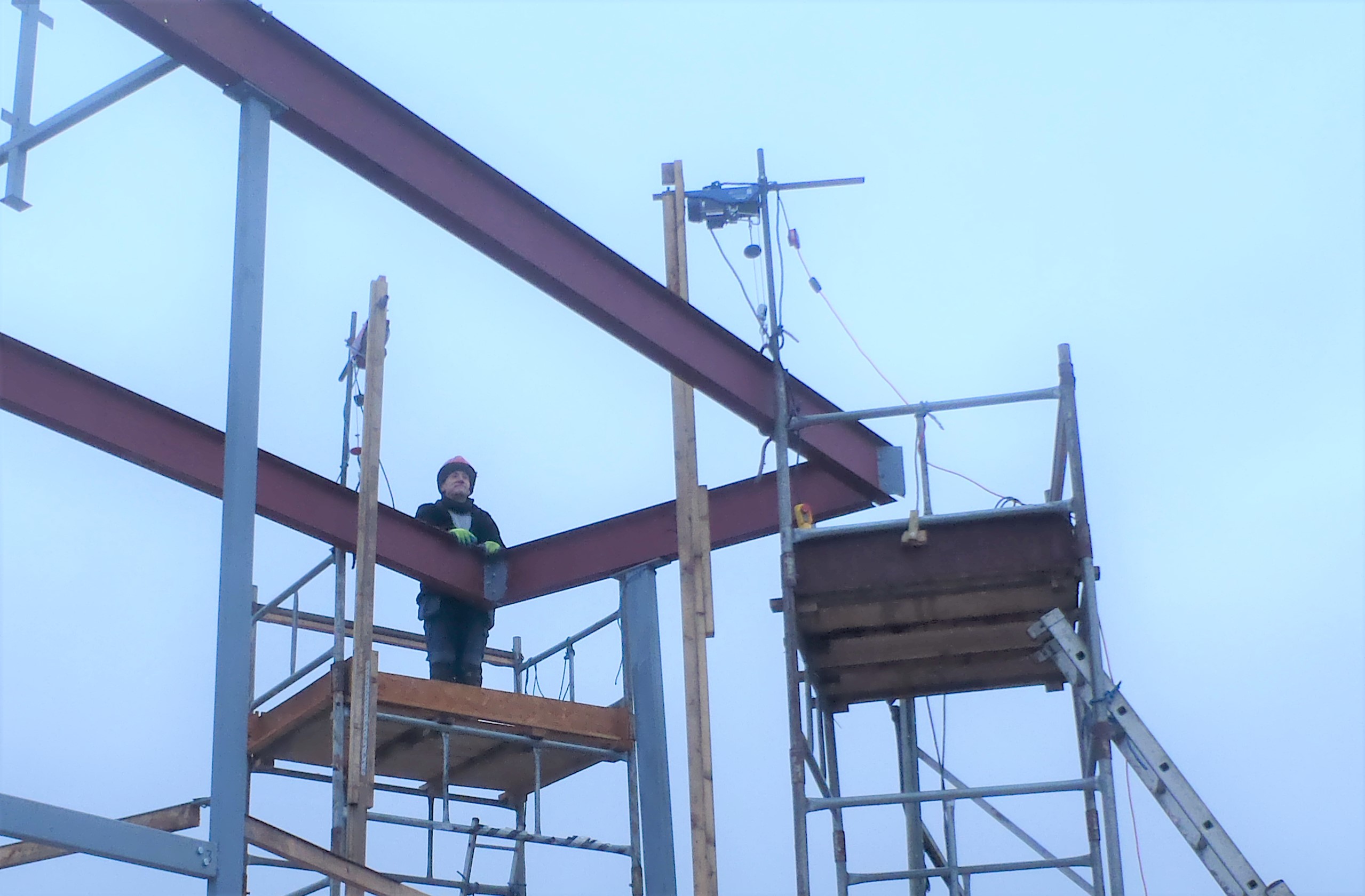
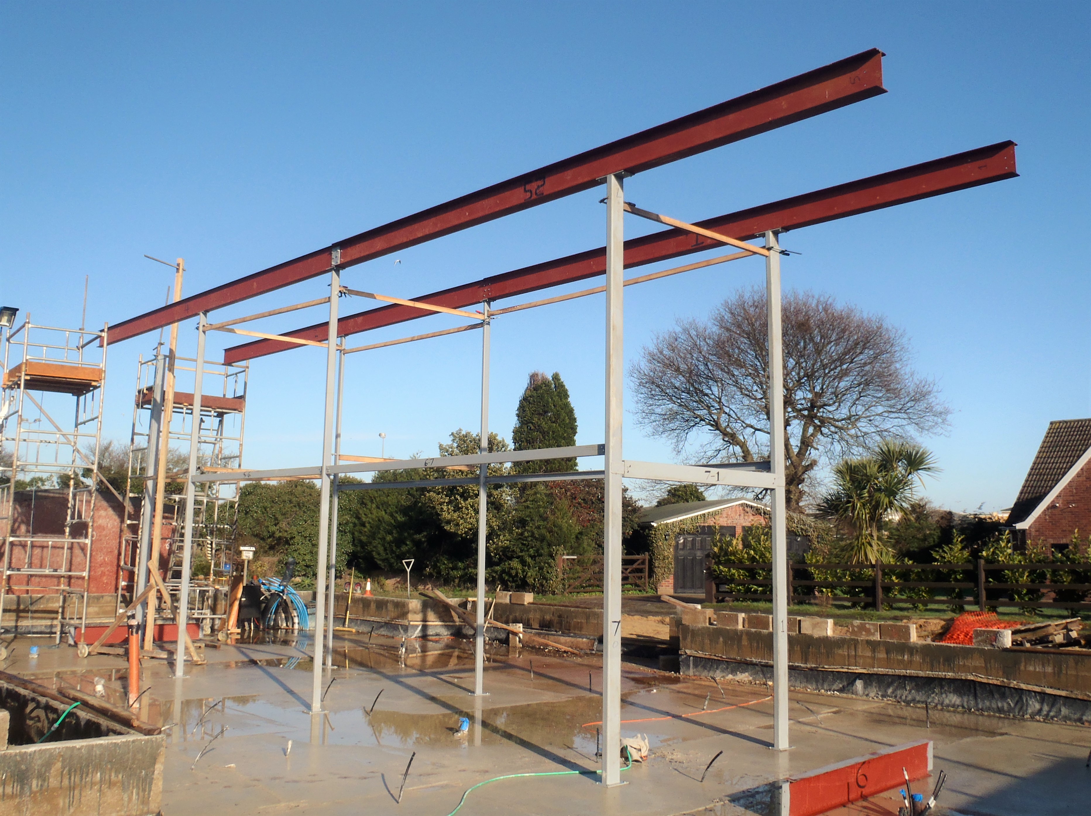
So after all this preparation work, we finally got to start lifting the I beam, stopping almost immediately to double check everything looks good, the wires are not twisted and are going into the winch drum correctly and everything else is correct. We continued with the lifting operation, and finally arrived near the top of the legs. The suspended I beam was quite easy to move on the wires so we could move it out a few inches to clear the heads of the clamps that are holding the wooden temporary struts and got the I beam the rest of the way to above the plates on top of the legs. We could swing the I beam over and lower down to plonk it, with a clang, on the legs!!
Then it was the moment to find out whether all the bolts holes lined up or not!!
And they did!!
Grin!
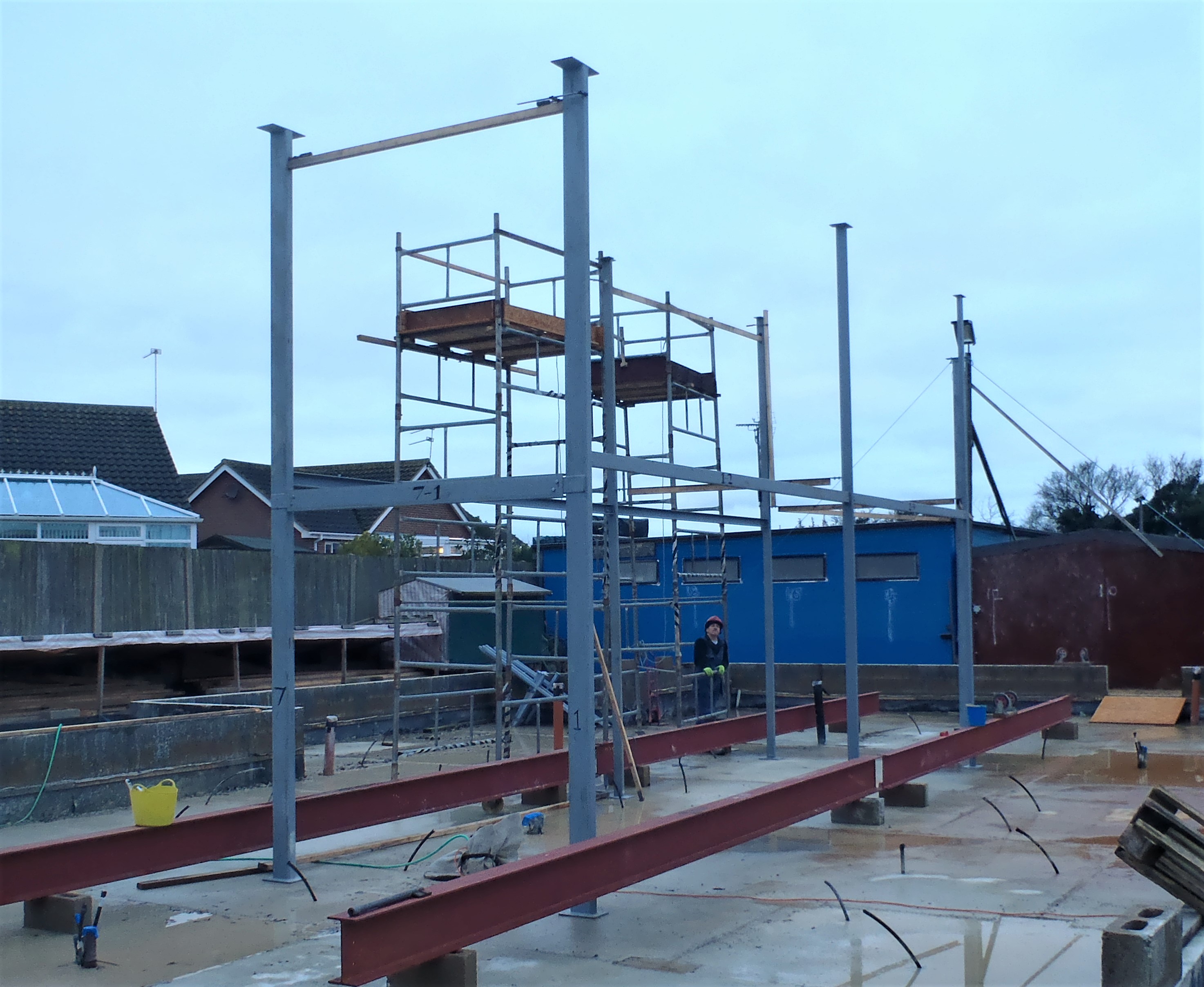
That was I beam number 1 in place!!
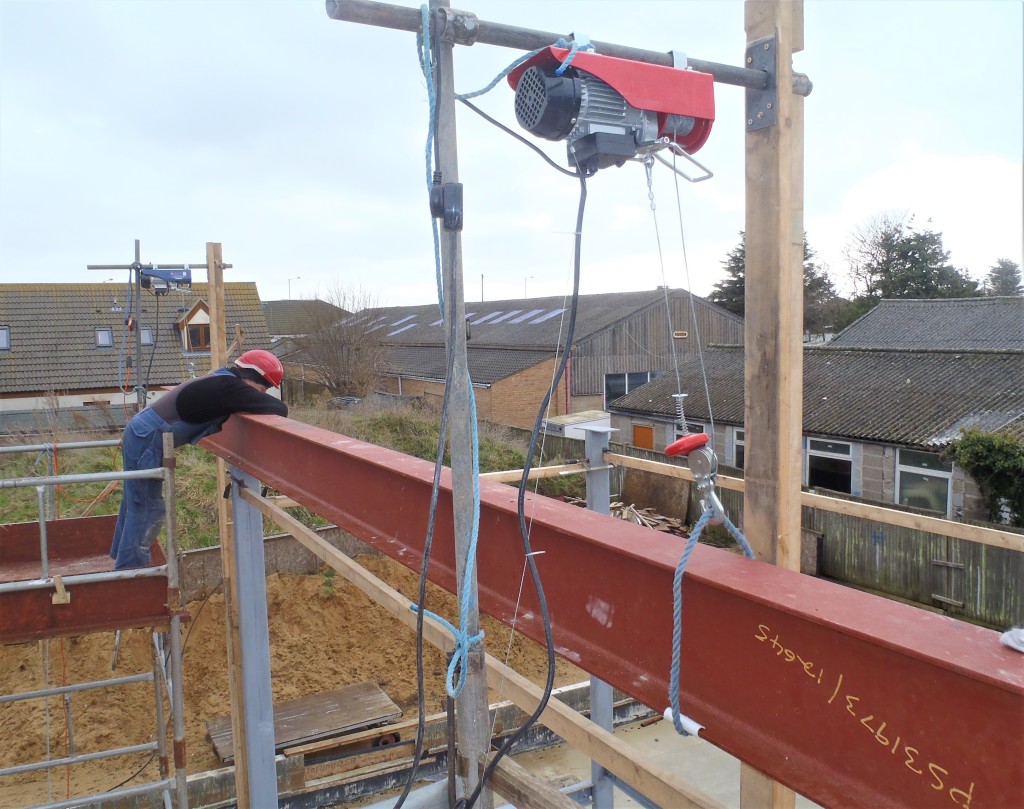
Beam-1-in-place-and-being-bolted-down
We moved the tower from Leg 1 to Leg 3 position and rearranged the crane poles and wooden leg ready for Beam number 2 and stopped for lunch.
After lunch, we repeated the whole process for Beam number 2 (which is a lighter and smaller at only 100m wide flanges (these being 6mm thick and the webbing only 5mm thick) and the same height of 300mm but actually a bit longer at 8192mm long. We lifted it up and got it up on top of the legs but this time, we had a 10mm thick plate which joins the two I beams together already loosely attached to this second I beam so we can bring together the two ends of the I beams and line up the holes.
We could line up the bolt holes on Leg 2 and also the webbing plate joining the beams together .. but .. we discovered that the holes drilled in the bottom flange of the I beam didn’t line up with the holes drilled in the plate welded on top of Leg 3!! Oh dear (and a few more choice words or five!) eeekk!
After checking that we had the correct I beam for this section of the framework, and measuring everything again and checking the drawings, it was a simple case of the original holes were not drilled in the correct place by some mischance of reading the tape measure or something.
So we had to lower the I Beam back to the ground, but we hadn’t unhooked anything at this stage as we hadn’t bolted anything and we don’t release the hooks off the rope until we have ALL the bolts in their holes and fully tightened up – just in case!!
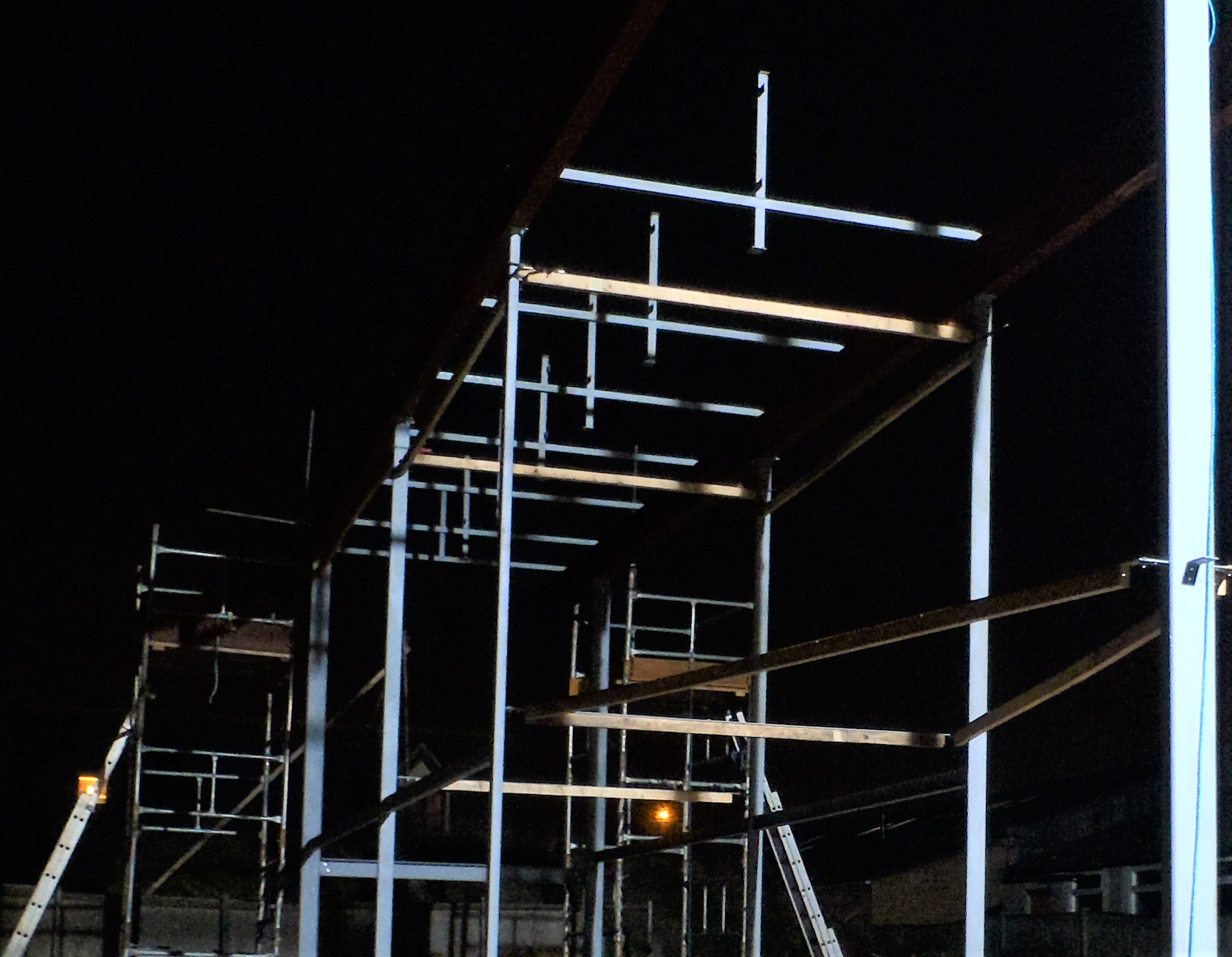
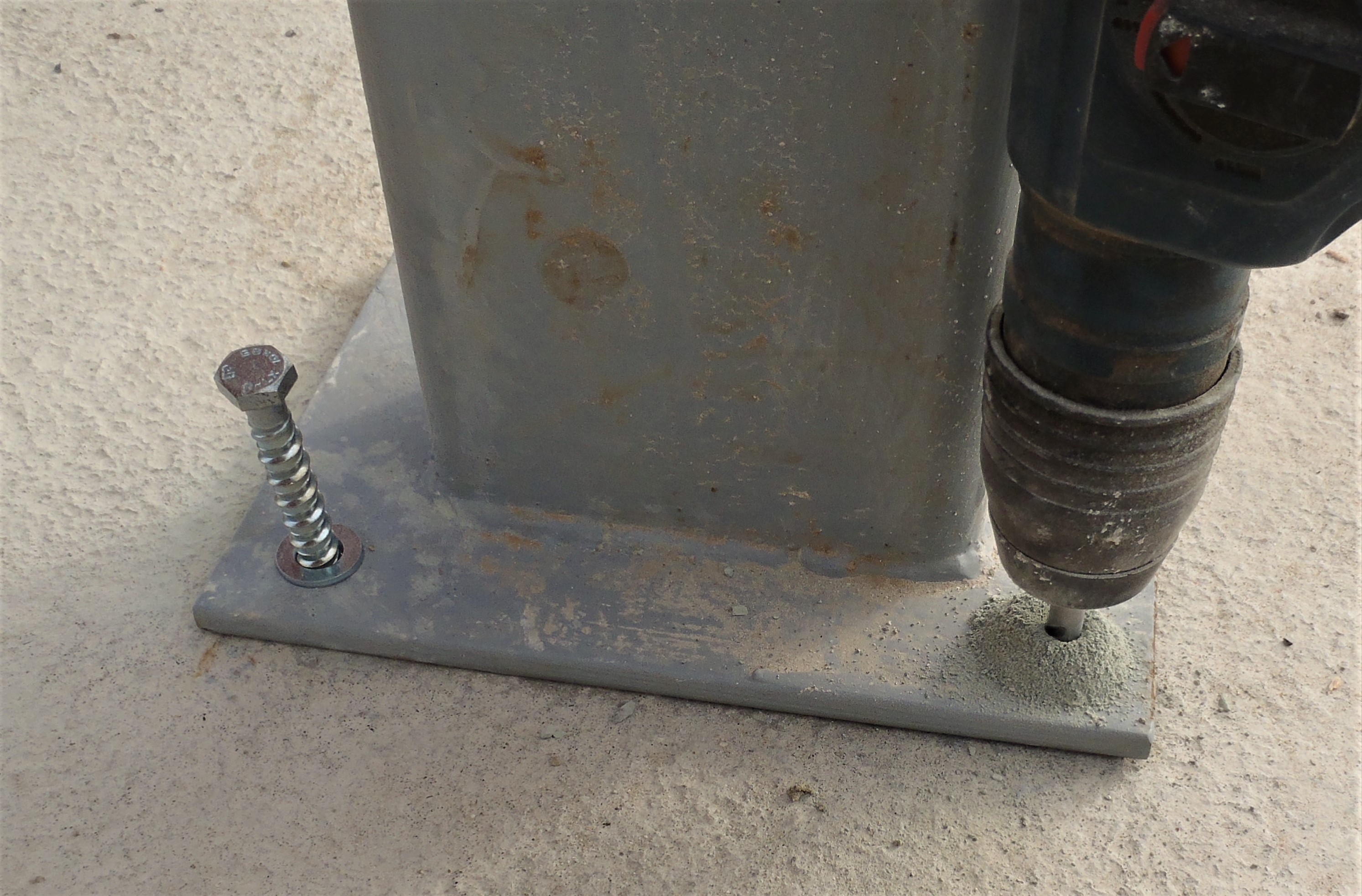
After careful measuring, it turned out that we needed to drill 4 more new holes 31mm further along the I beams so after careful marking and punching the steel, we drilled the initial 5mm pilot holes and then drilled out the holes to the required 13mm but at least we tried too! The 5mm pilot holes were fine and cut through the steel fine but when we tried doing the 13mm holes, it only did so far and just stopped boring through. It just blunted the drill bits!! We did manage to use a 10mm drill bit to cut the holes wider but still wouldn’t drill the final 13mm holes. We did manage to do 2 of them but the last 2 just wouldn’t go so we ended up filing the last holes by hand! What a Palava! It was dark by this time and we were working under our floodlights!! Grin!
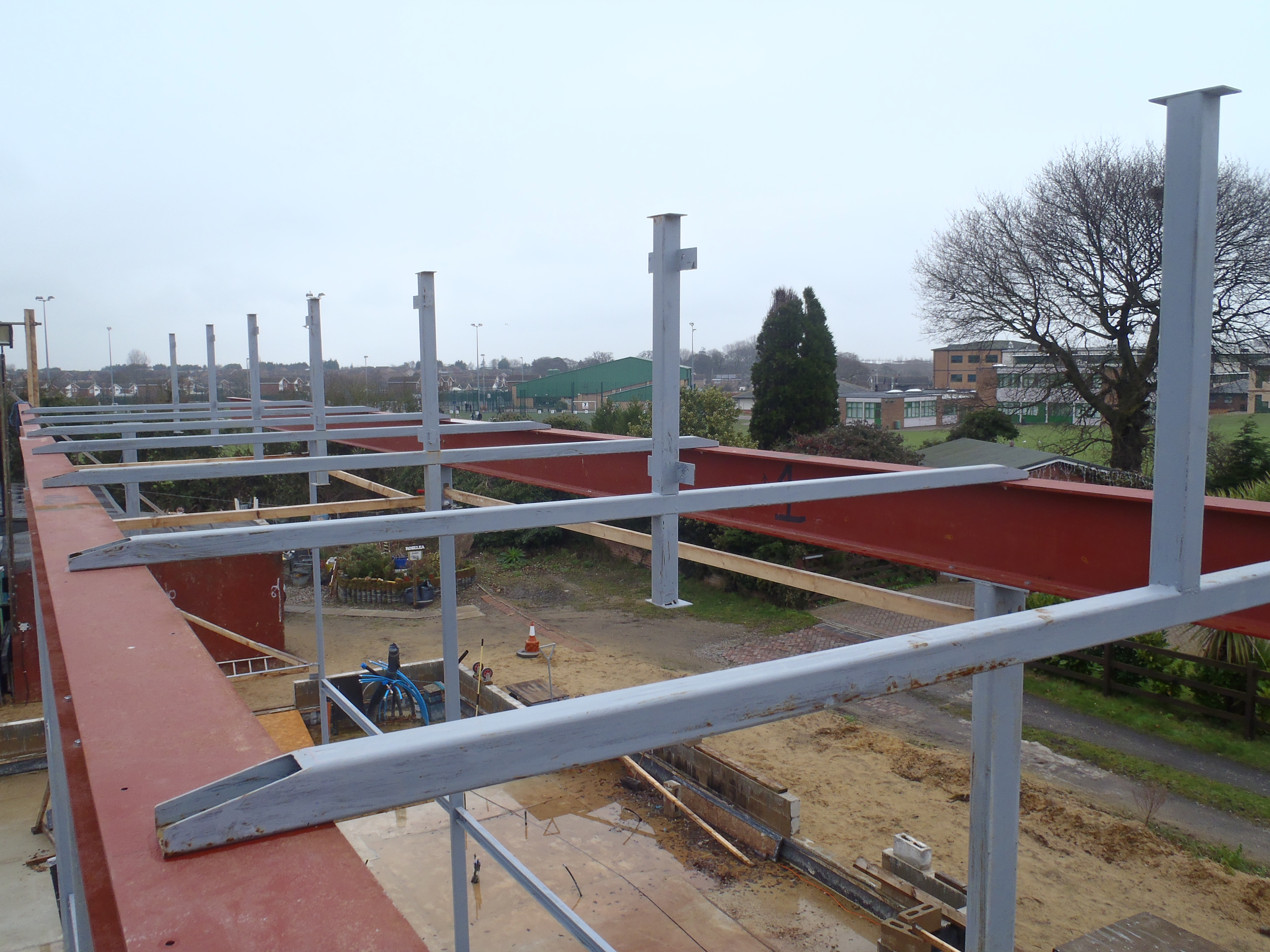
We put everything back together again and this time, we lifted the I beam up and plonked with another nice clang and the bolt holes all lined up! Hurray!!
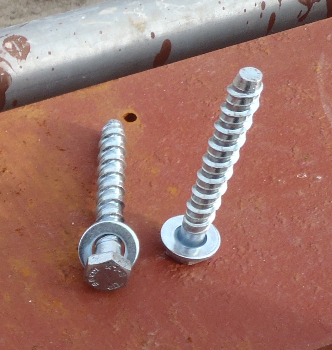
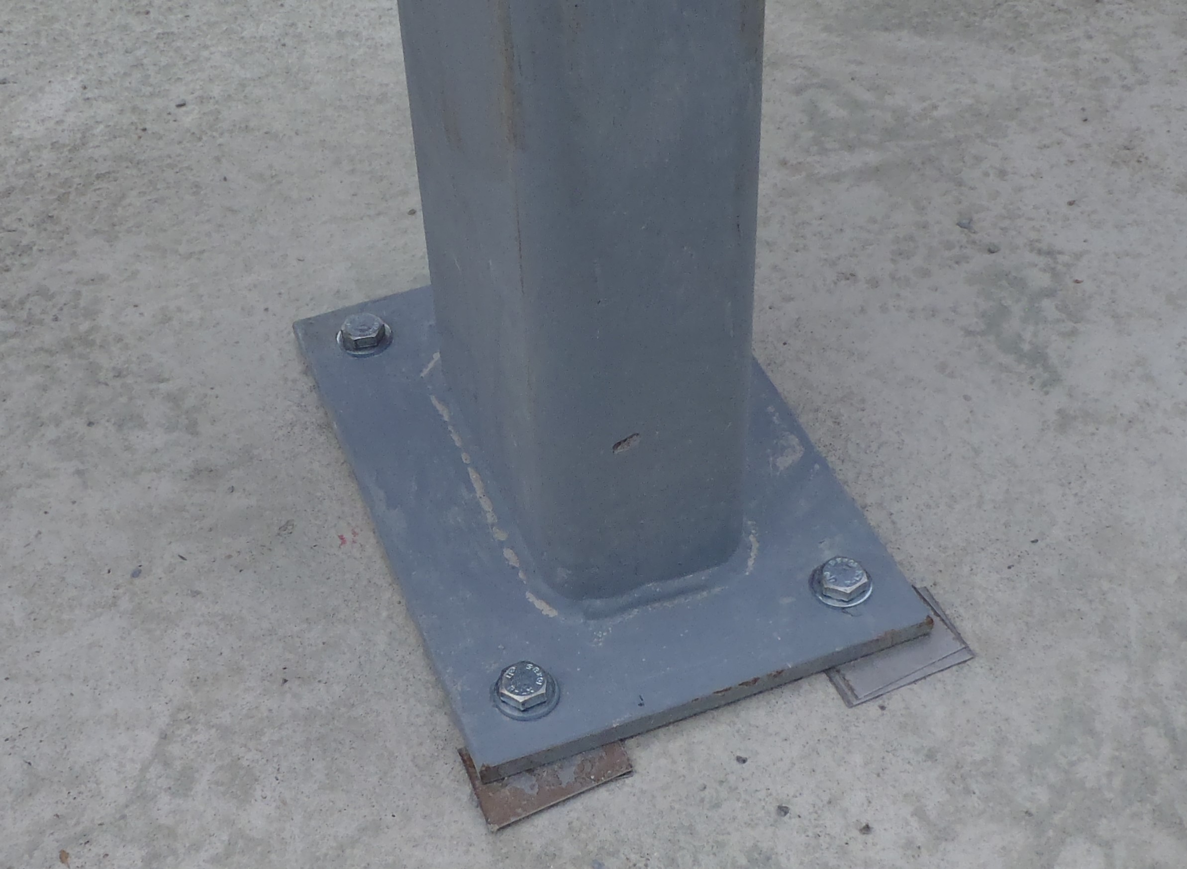
We did all the bolts (6 on the webbing plate, 2 on Leg 2 and 4 on Leg 3), all is tightened up and locked down!

Beam-2-in-place-and-fixed
We finished off by undoing our hoist machinery and brought them indoors just in case it rains overnight. And that concluded our day of lifting 2 I beams into place!! Phew!