Category: Energy

  • Heat Exchange module Trials and Conclusions

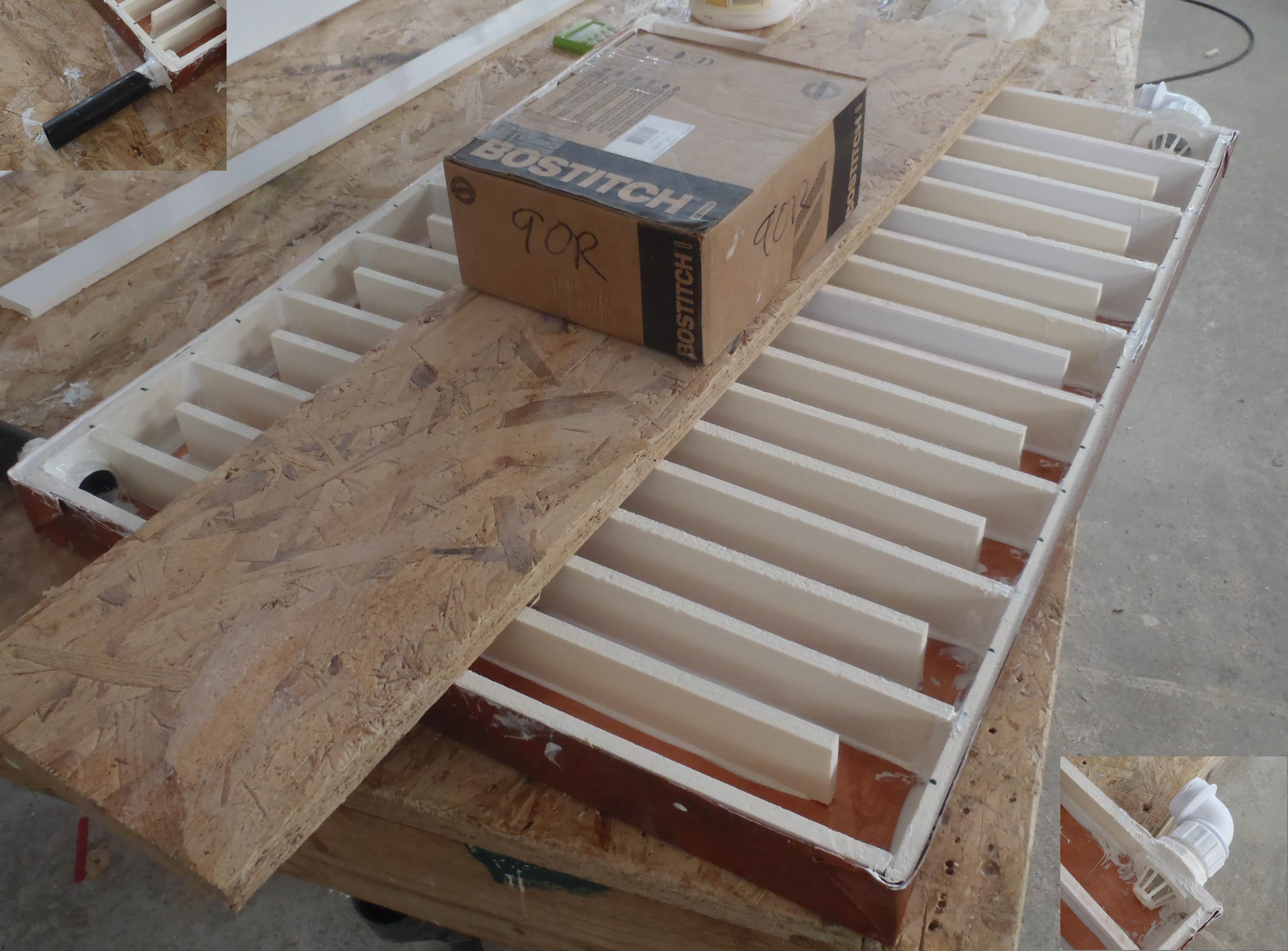
    The water test was performed on the heat exchanger module outside using the garden hose! The “maze” slowed down the water that it took well over a minute (nearer two) for the water to travel from start to finish! It did build up inside the channels but didn’t reach the top and overflow!

    The waste trap did struggle to start letting the water through as it was in the horizontal position but after wetting it, it got going! There wasn’t enough head of pressure to bend the rubber seals apart and being brand new and dry, it was probably sticking together!

    We increased the angle to see how much the flow changed and reduced the water level but in conclusion not a great deal! We were only changing it from a 1 in 75 slope to 1 in 40 slope .. 10mm drop to 18mm over the length (750mm) of the module.

    = = =

    The Copper powder arrived and we mixed some together with some polyester resin and spread it out on a test piece of wood. After lunch it was not as conductive as we had hoped! It wasn’t the magic cure we were looking for to solve the problem with making a good thermal connection between the copper sheet and the copper pipes.

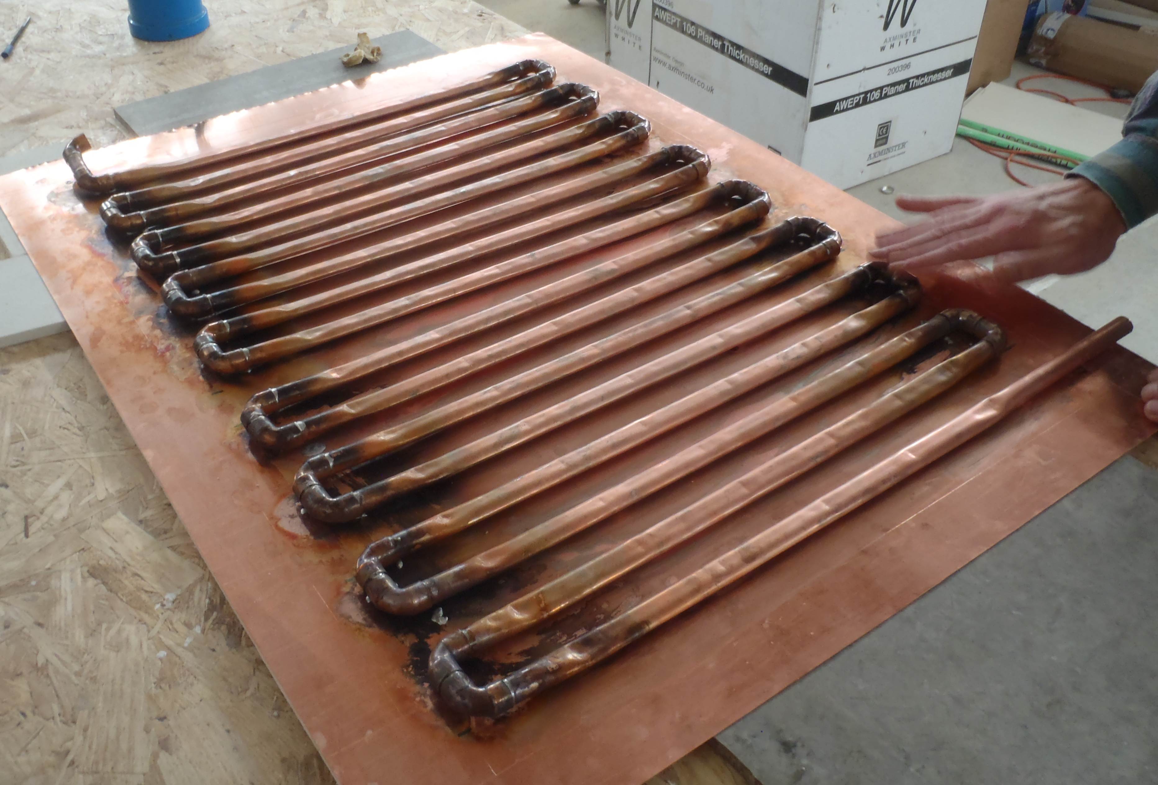
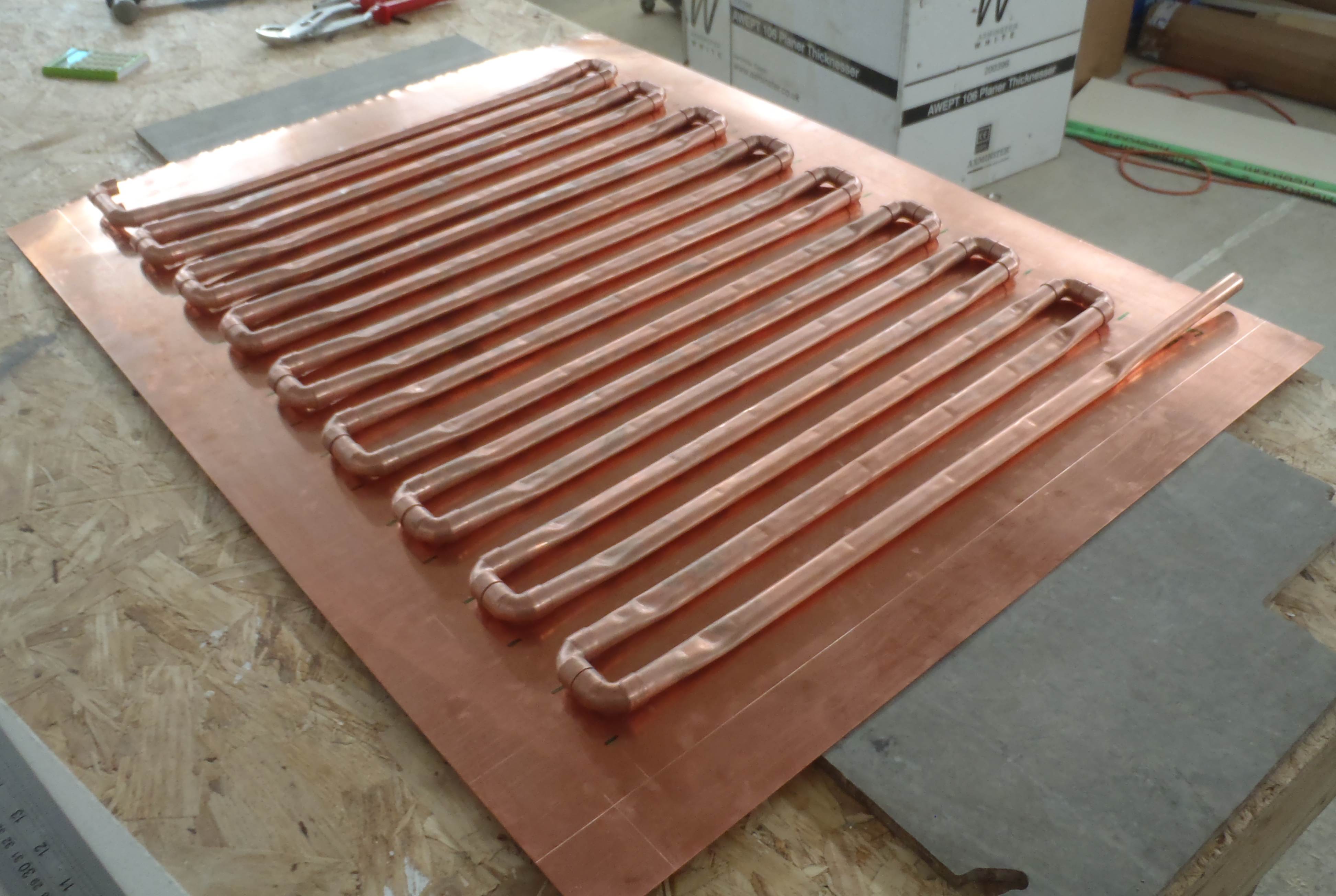
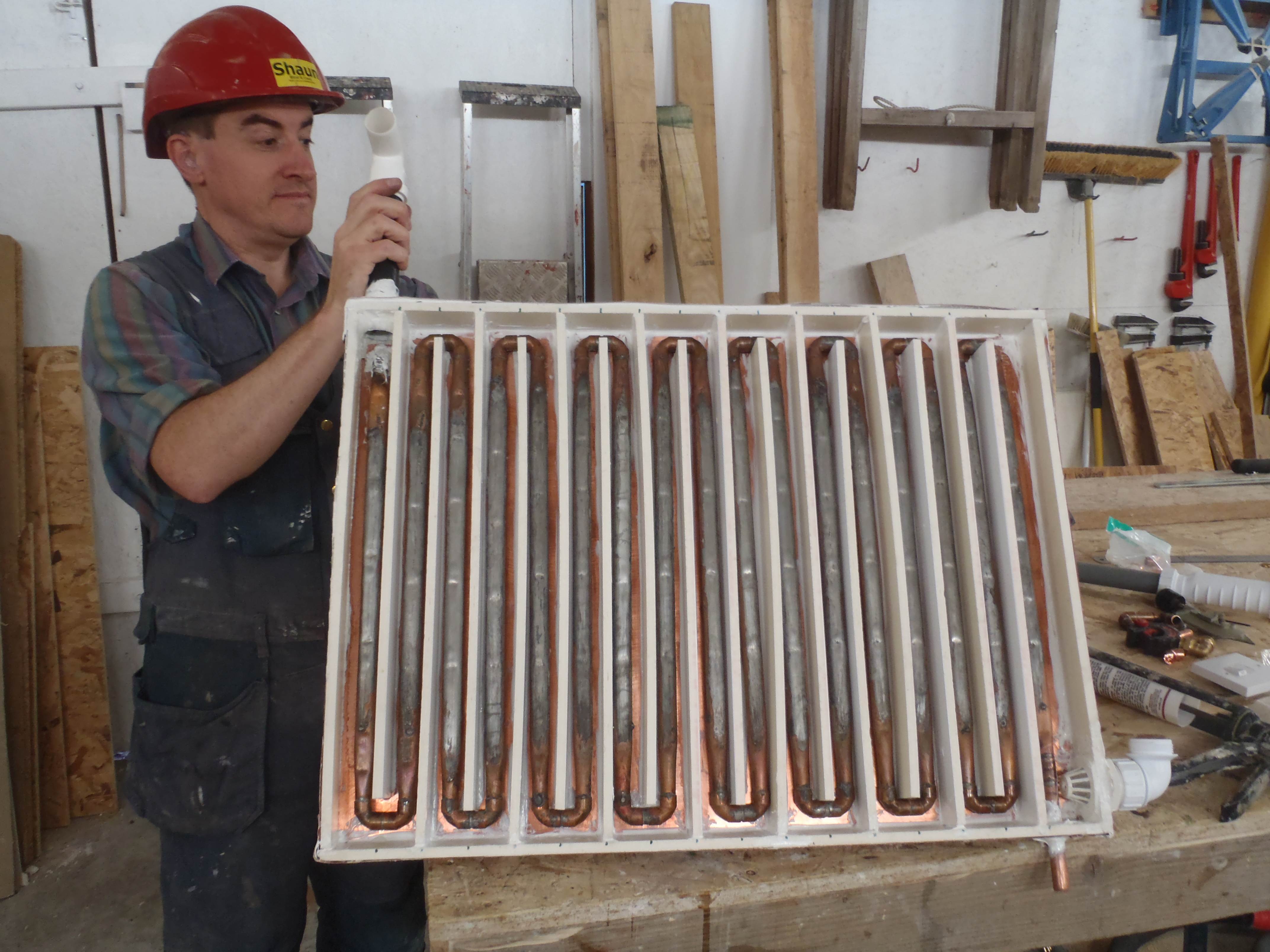
    So throwing off our thinking caps, we decided, with the results of the water test in the morning, putting the copper pipe directly in the water flow inside the “maze” was the best solution at this time and place!

    So we adapted the input and output pipes, drilled two holes in the copper sheet and threaded everything together, sealed all the new joints back up with the usual PU sealant and we wait (again)!

    In the meantime we carefully lowered the drain pipe in the garden room’s floor to its lowest point to allow us the maximum range of tilt (up to a drop of 40mm) of the heat exchanger. Then we fitted the shower pump control box on the inner wall of the shower cubicle, connecting the electric and data cables through holes in the wall (sealed up!) and fitted short plastic pipes to the shower’s cold and hot water inputs, also going through the wall (also sealed up!).

  • Heat Exchanger Stage 2

    Yesterday and today were spent on trying to get the copper pipes soldered to the copper sheet. But it was proving to be quite difficult with several factors playing against success! Like for example the flux was drying up during the heating up process and leaving “dirt” to stop the solder sticking to the copper. Pre-tinning the surfaces was tried but the heat required to melt the solder was also causing the already soldered joints of the U bends to come apart or at least breaking the joint and allowing potential leaks. We put on our thinking caps again!

    The next trick to try is copper powder mixed with a binding agent (like polyester resin) and putting the copper pipes on a bed of this “paste” of copper and fixing everything down with silicone sealant. We await for the delivery of the copper powder!

    In the meantime, we bent up the sides of the copper sheet to form the tray, cut two holes in the required places for letting the waste pipe water in and out. We also sliced up the soffit board (10mm thick foamed PVC plastic) into 45mm wide strips and “glued” them into the copper tray (using PU sealant) to form the maze like long winding path for the waste water to flow over the copper sheet while transferring the heat down into the copper pipes containing the fresh cold water (hopefully getting warmer!) running underneath the copper sheet!

    We have also ordered a half dozen temperature sensors to monitor the performance of the heat exchanger and the “system” efficiency of the Shower as a whole.

  • Heat Exchanger for Shower

    Today we cut the copper pipes (474mm long), 17 of them, along with 18little (24mm) pieces, each to connect the two right angle bends (36 of them!). The whole thing forming a ladder like structure. This structure will be placed in close contact with the copper sheet.


    The pipes are now soldered together but when we tried to solder the pipes to the sheet, the sheet started warping up! We think this is caused by the heat expansion differential of a local spot against the rest of the colder sheet. Our thinking caps are on!

  • Heat Pump Pipes Day 4

    Day 3 – Tuesday 31st August

    Finished laying the pipes in the trench.

    shows all the pipes in place

    Now we have to cover them in fill (sand/soil) to the level of the bottom of the rainwater tank & soak-away. The boards down the length allows us to drive the Kanga Kid around collecting and dumping fill. We dumped fill over the edge in the corner of the trench and moved as necessary. By the end of the day we have placed half of the fill.

    pipes covered in fill.

  • Earth Tubes Design Conclusion!

    We have finally settled on a design of connecting up all the earth tubes and getting the air in and out of them! We have 12 tubes all together, each one being 150mm (6inches) diameter internal) in order to provide time for the air to exchange its thermal energies with the surrounding thermal mass! The 12 tubes is equivalent to a single 600mm (2feet) diameter pipe!

    After consulting with our friendly structual engineers, who advised us that our original design of using concrete blocks to construct a chimney and tunnel to pass the air down to the tubes, has potential problems at the joins due to the loading pressure from all directions but especially the sides, at 2.5m (8feet) depths! They advised the use of pre-casted concrete pipes segments to make the chimney and tunnel / chamber but this lead us to realise that we could route the tubes themselves upwards with 90degrees corners and terminate them inside the buildigs! This makes it so much easier and avoid mssing around with concrete blocks, pouring concrete around them and other reinforcing methods or drilling holes in the sides of concrete pipes!!

    So Many Thank goes to our engineers at Burrell Partnerships of Norwich!!

  • Solar Survey

    Performed a solar survey today. This is a check on the site of your solar panels to see what may obscure the sun at different times of the year.

    To do this I produced a 300mm circle divided in 10° segments and put this on top of a tall stepladder so than when I stood on it my eyes were a similar level to the final panels. The stepladder was orientated to North-South Line (Used Google Earth to find a sight line). Then I used a inclinometer (in my case a electronic spirit level) to map the angle of the top of each item from horizontal around the circle and note them down. I then took a series of photos to get a panorama at the same level.

    Stitching the photos together gave me this …

    The panorma around Roselea.
    The panorma around Roselea.


    I then traced a line along the top of the obstacles (Faint Red line above).  I Then got a SunChart from the University of Oregon (Lat.-Long. from Multimap/Google Earth). Then took the horizon line from picture and scaled it onto the Sunchart to get this :-

    Sun Heights above Horizon for the Year
    Sun Heights above Horizon for the Year


    For more info see the Solar page.