Blog

  • Production Line Starts to Rolls Off Legs for Great Room

    Today, we spent the time slicing and chopping lots of materials for the creation of the Legs for our Great Room. After carefully checking yesterday our Leg Element and how it fitted, we were ready to speed up production of the various individual items to make a Leg.

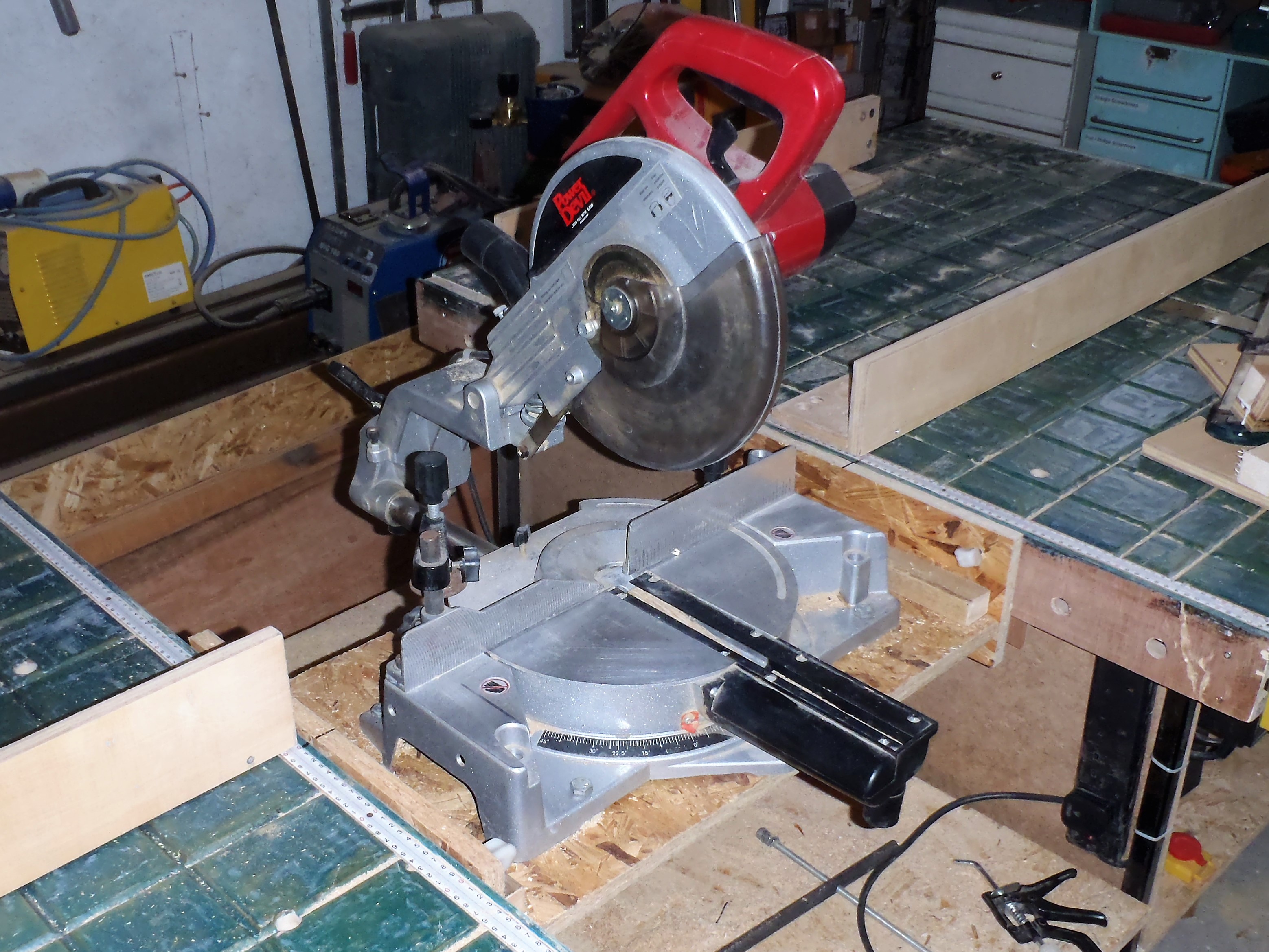
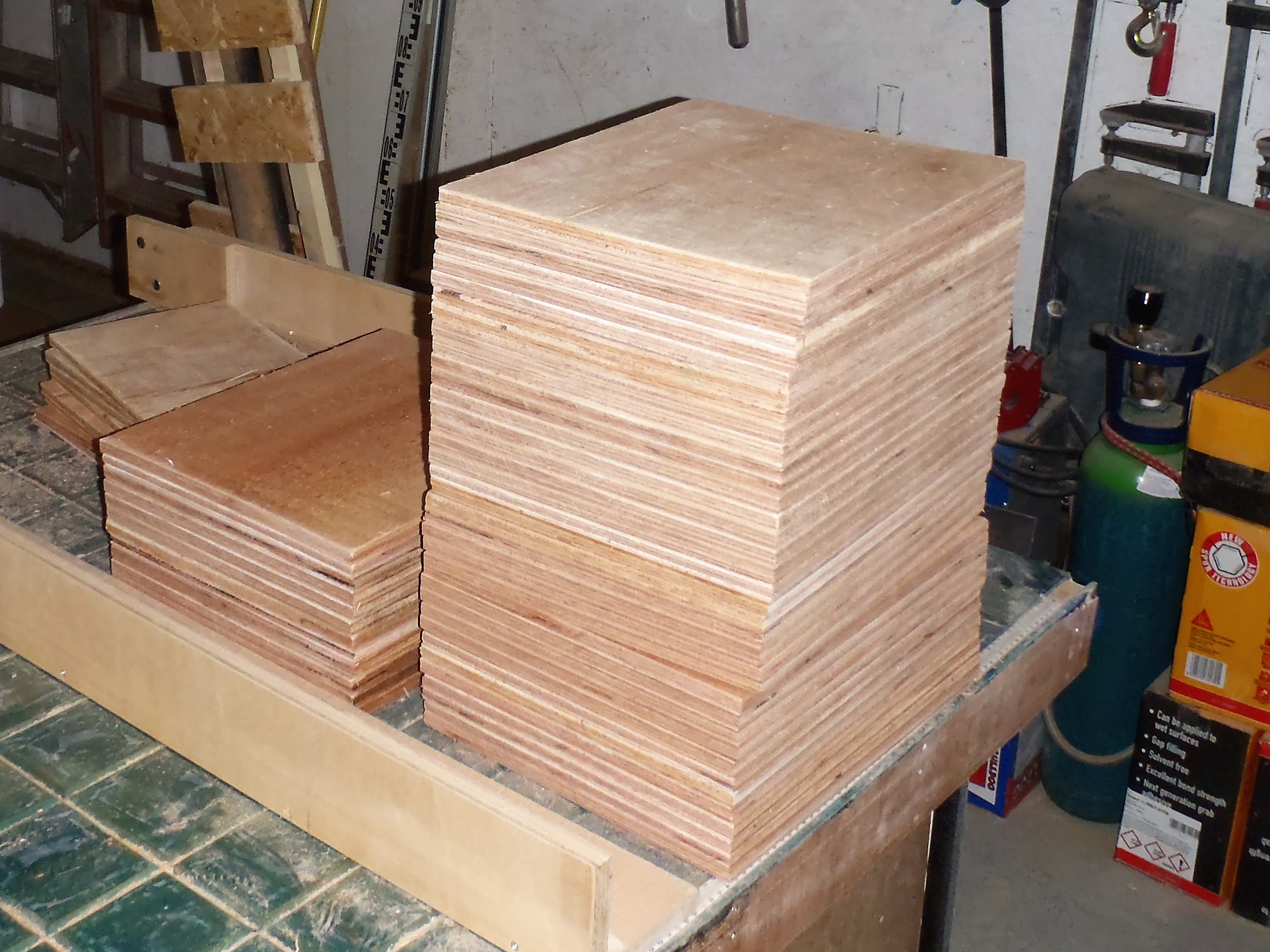
    We spent the morning slicing up 12 more sheets of our 11mm structural plywood into over 300 webbing pieces, using firstly our circular saw module and slicing the full sheets into 4 x 300mm wide strips. Then taking each set of 4 strips, we put it through our chop saw module every 370mm, creating our neat webbing items. This is enough webbing for all the legs.

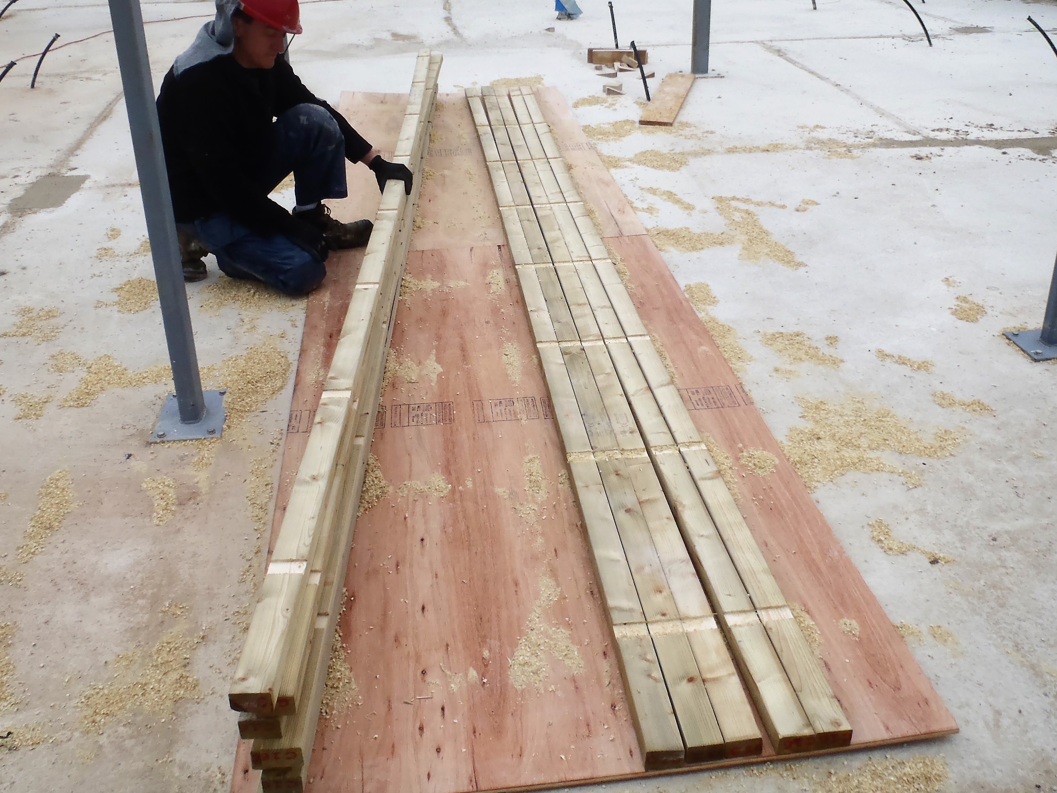
    Then, we brought in 33 lengths of our 63mm CLS timber to have them chopped down to the required 3070 mm size, and piled up next to the 89mm CLS pieces we have already done.

    Pile-of-cut-wood

    Pile-of-cut-wood

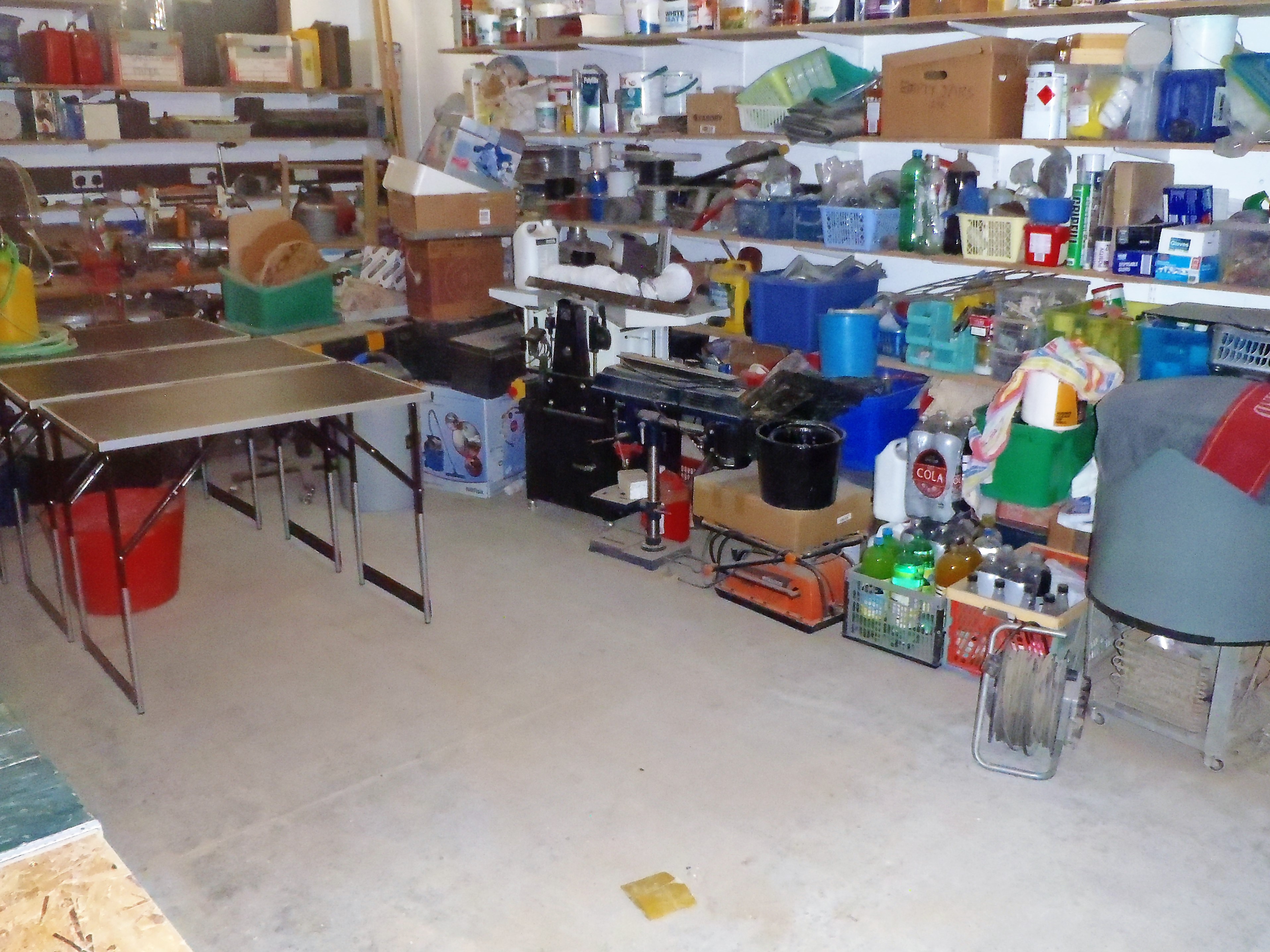
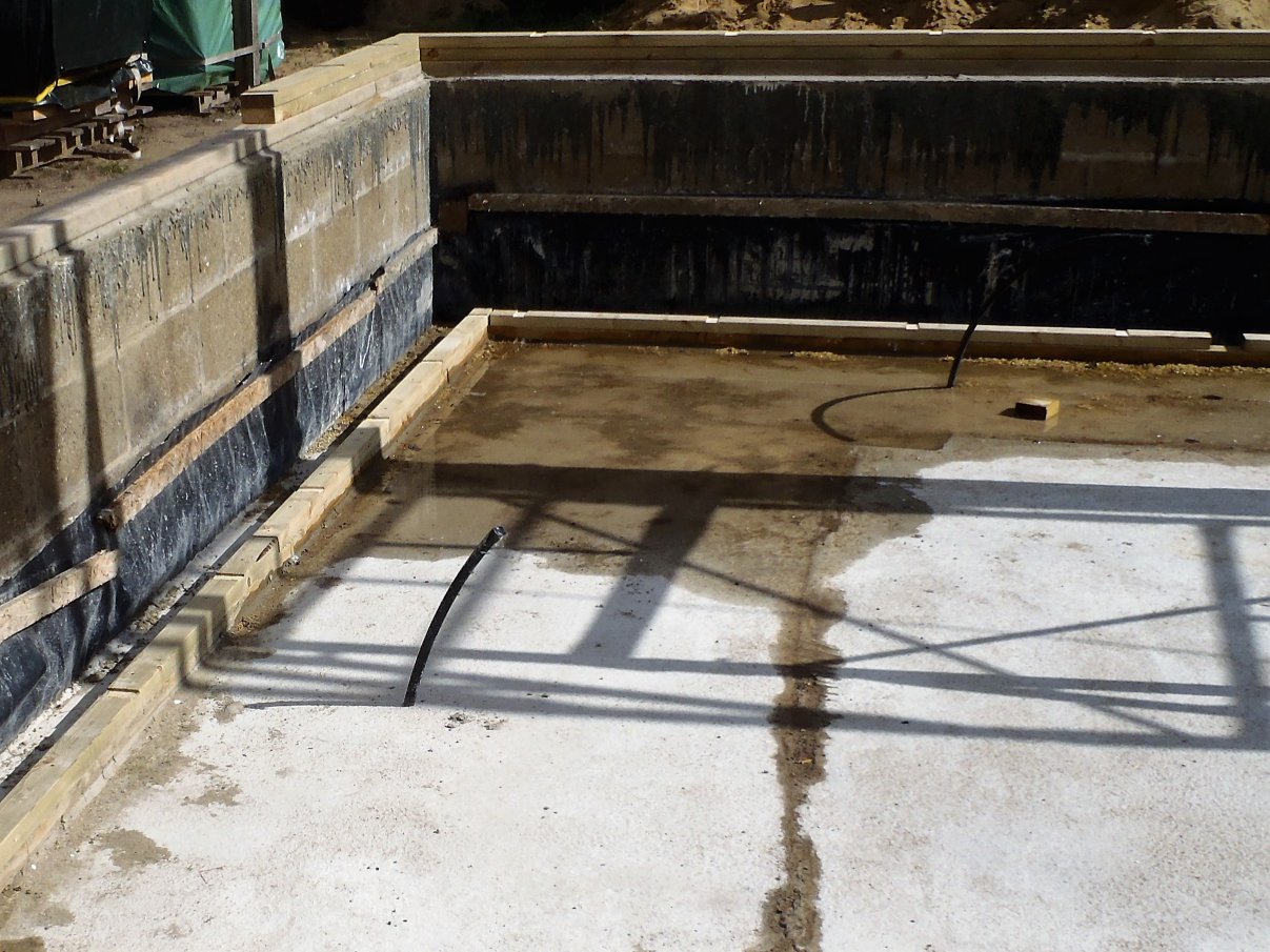
    After lunch, we tidied up the workshop of all the sawdust we created from the morning’s work, tied up in bundles the left-over pieces of 63mm into 12 piece piles and tied up a heap of plywood pieces, all using old string we had lying around. All these bundles were then moved outside to get them clear of our working area. The CLS went on a spare pallet  near the other pallets, and the plywood stacks went under the rain protection in our swimming lane.

    Then we resumed the assembly of each Leg itself. We did a further 6 more “left hand” orientation which will be fitted on the left hand side of the 5 windows and the door in the Great Room. It was the usual job of placing each element into the jig, gluing and then nailing it all together.

    Now we needed to switch the jig over to make “right hand” types of the Legs, so a quick unscrew of the barrier to slide it across to the other side of the jig and hey presto .. we now have a template for making the leg with the plywood webbing pieces on the other side of the Legs.

    We started the next Leg to only hit a snag .. the glue stopped flowing!! Oh why does it stop just right now??! We took it apart and checked the pipe going down inside the bottle of glue by blasting full powered  compressed air down the pipe, did the same for the flexible hose section and finally got to the nozzle and guess what? It was Blocked! Just Typical that we started at the wrong end!! We cleaned out a lump of half set glue out of the nozzle and by this time, it was approaching finishing time for the day. it was slightly earlier this time as we had other commitments on.

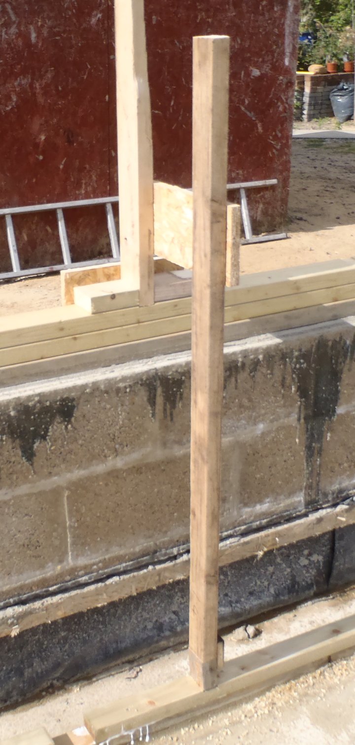
    We did actually finish this leg off! Tomorrow, we will resume our assembly of more Legs for the Great Room and after that, start getting them into position outside in the house itself – yippee!
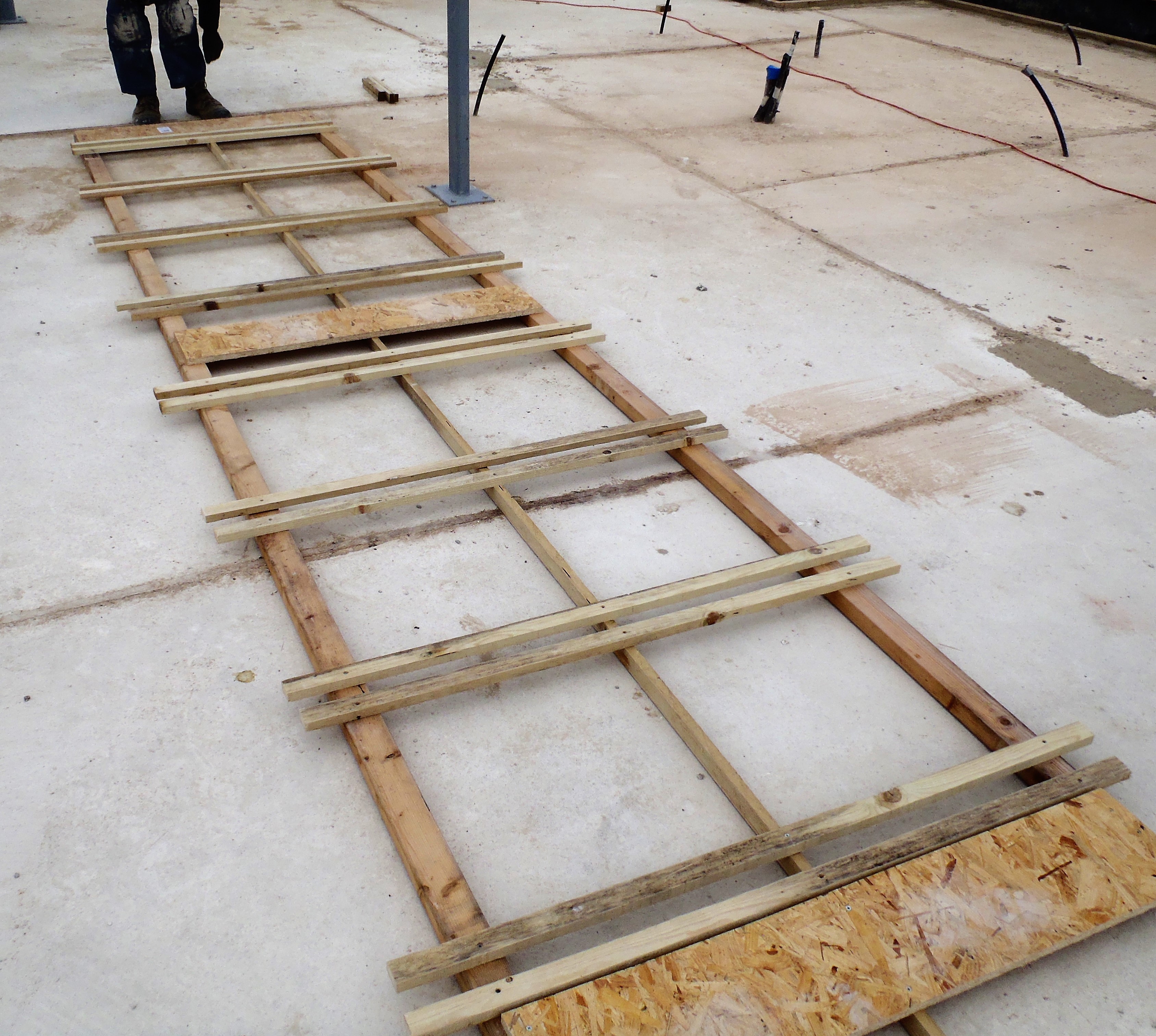
    First-7-legs

    First-7-legs


  • Creation of Legs Begins

    Today saw the start of the creation of the External Wall Legs. These legs forms the main structural load bearing elements for both the roof (on the outer leg) and the first floor support (on the inner leg).

    First-leg-errected

    First-leg-errected

    As the photos shows, it is a very tall twin vertical lines of CLS timber, the outer one being 89mm wide and the inner one being 63mm wide, connected together with three plywood pieces measuring 300mm high and 370mm wide (this being the actual depth of the External wall).

    We did a block job of cutting up 18 lengths of the 89mm CLS in our chop saw module to produce 34 required length of 2393 mm long pieces. As some of you may have noticed the odd difference between 18 and 34 and not 36 lengths, several of the timber that came off the pallet had cracks in them so we chopped them around these faults and had to fetch another piece from the stack.

    We made a jig to repeatedly position each of the parts in their correct location and have the three 11mm thick plywood spacers glued and nailed into the correct place each and every time.

    Jig-for-legs

    Jig-for-legs

    Then, getting one length of the 63mm CLS timber off the pallet, we sliced this down to 3060mm long and inserted this into our new jig template, along with a 89mm pieces we made earlier and glued and nailed the plywood pieces into place.

    Nailing-spacers

    Nailing-spacers

    Our first completed Leg element we took outside to test how it fitted and we discovered a mismatch with our expectations against the survey task we did on Monday. We had concluded that we needed a length of 840mm below the upper level but as we realised, it wasn’t enough! We had a mismatch with our measuring on that Monday and today. It seems that we should have doubled checked the method we used to calculate this required distance by using a different method and tools and we would have realised our mistake. We actually needed to increase our required distance to 850mm to make sure we can set the Leg perfectly vertical.

    So this first Leg is now reassigned to be a Leg in the Utility Room beside the Window’s left hand side instead, it fitted nicely there – grin!!

    Having made the adjustments to our jig, we made a second Leg and this time, we had the flexibility to shave little bits off the end of the inner leg, bit by bit, until the Leg was vertical. We used a combination of our battery powered circular saw and a heavy razor sharp guillotine to slice off large and thin slivers respectively. We also had a length of timber with sand paper stapled on one edge to help us clean up the slots and if necessary, rub the slot ever so slightly deeper to provide that final adjustment.

    This Leg went into the Great Room on the wall labelled in O the number 8 slot, the wall is part of the extension facing our Swimming Lane.

    Finally, we had time to make a third Leg and repeating the process we did on the previous leg, got this one fitted as well. This Leg went in also in the Great Room but this time on the Kitchen / Great Room Front Wall which is labelled A and Slot number of 7.

    Tomorrow, we can now ramp up the production rate and do another 32 Legs to do all the Great Room Legs as they are all the same size, before we move onto the next wall.

  • Septic Tank Serviced and Workshop Tidied Up

    This morning, we had the Septic Tank serviced and emptied. We then gave it a once over, cleaning the various inlet and outlet pipes to make sure they were all cleared and flowing nicely. Also, the electric air pump was opened up to check the moving parts were all clean and in good working order.

    Then, after lunch, we carried on with tidying up the workshop, sorting out the tall rack of sheet materials and throwing away little pieces and putting similar items onto their own shelves. It has been rather jumbled up over these last few years and now it is nice and neat again!!

    The Workbench is now ready for the commencing of creating our External Wall Legs which will be tomorrow – at last!

  • Chop Saw Adapted for Modular Work Table and Spring Clean in Workshop

    A mixture of sorting out and tidying up our workshop and also adapting our large chop saw for our modular workbench system.

    Chop-saw-module

    Chop-saw-module

    The chop saw is our old one we have had for years, capable of slicing material as wide as 300mm and as deep as 80mm, which will be very useful when we come to slicing roof rafters and floor joists. The saw is able to be slid into place and be locked into position with it’s own fence lining up with the workbench’s twin fences on either side.

    While that was being executed, the whole workshop got a spring clean, starting with our box trolleys on wheels, four of them in a line under our stack of sheet material. Each of these boxes contains off cuts of various material like OSB, pine timber, plywood and Oak hardwood pieces. We decided that any piece that is smaller than 4 inches goes out and off to the fire pile.

    The new chop saw was use to cut up strips of plywood to start to make the spacers which will hold the outer and inner legs apart, this is  a pile of 48 but we will need over 300 of them….

    Leg-Spacing-pieces

    Leg-Spacing-pieces

    Then the old saw table (a full 8feet by 4feet) was put away by removing its four legs and sliding the whole thing up onto the top tier of our rack of sheet material. It was far too large to have around, now we have our new modular workbench. We needed the room to have a pile of building elements to be stacked up while the glue is drying and room for raw materials to come in and get processed into whatever we need for the house construction.

    Empty-space-in-workshop

    Empty-space-in-workshop

    Tomorrow, we will just finish off the tidying up operation and then start chopping up 89mm and 63mm CLS timber to make our External Legs!!

  • Final and Double Check Measurements

    This morning, we went around with a spirit level and our talking tape measure, to measure the distance from the upper wall level, the 89mm wide footplate, down to the lower level, the 63mm wide footplate on the concrete.

    We balanced the spirit level horizontally, with the tape measurer stuck on the end pointing right angled downwards, and at each and every slot around the Perimeter Wall, pulled the tape down and listened to the announcement of the distance. This got written down directly onto the timber.

    The range of measurement was between 833mm to 840mm, with most of them being 833mm and 835mm. Matching this series of distances, which is after all, only a relative amount from the upper level down to the lower level, we needed to see if this set of numbers, when added to the absolute height  of the upper level, does anything to our calculations and any adjustments we might need to make.

    The conclusion was no. A Good Old Fashioned No! Hurray! Grin!

    This means that we now know how long to make the inner leg to ensure there is enough excess wood so we can shave small amount off the end with our guillotine tool and get the whole leg assembly perfectly vertical when we install each leg.

  • Final Inner Footplate Layer with Slots Gets Glued and Nailed

    We had a slightly delayed start today’s work because we had rain overnight of about 3mm and we wanted to make sure the wood planks already out there will be as dry as possible before we use our glue. The wood glue is normal everyday stuff and it doesn’t work very well in damp conditions. So we started 11:30am instead of our usual time of 10am.

    So starting in the corner of the Utility Room, we went around clockwise, laying down the second and final layer of the Footplate, this layer having the slots already cut in the timber.

    Alignment-gadget

    Alignment-gadget

    We used our Alignment Tool as shown in the picture above, to lock into a slot on the outer Footplate, and the new piece we were putting down then was lined up to make sure all the slots are in sync. We glued and nailed this strip down and repeated this process all the way around.

    No problems to report and we used 16 lengths out of the 24 lengths we had slots cut into yesterday. the other 8 (plus another 8) will be used for providing the Top-plate to position and lock the tops of the legs when we got all the legs built and set into place.

    Second-layer-of-inner-footplate-installed

    Second-layer-of-inner-footplate-installed

    The final task of this particular stage of building the outside walls, is to laser measure the inner footplate, or at least, measure the distance from the lower level to the upper level so we can cut correct sizes of the 63mm CLS timber for the inner legs and only have to make minor final adjustment on the spot to ensure that the wall will be as vertical and solid as possible.

  • Built a Template and Cut More Slots

    Today, we made a long flat template that will hold 12 lengths of 63mm wide CLS planks and guide our router machine to make a series of 40mm wide slots, spaced out regularly at 612mm intervals. This is used like the temple from earlier to get a consistent spacing on the legs.

    Slot-cutting-jig-for-multiple-pieces

    Slot-cutting-jig-for-multiple-pieces

    It measured 4.8metres long (16 feet) and 1 metre wide, with 8 pairs of short rails (made from 19mm by 25mm battens) screwed down the length for guiding the router to go up one side and back down the other side.

    We got 12 CLS timber planks off the pallet and laid them all in a tight group on the ground, and laid the template over the top of them. we then carefully sliced away wood to leave a groove in the flat surface of the CLS timber, ready for the inner leg to lock into when we start building the exterior walls.

    Slots-cut-in-multiple-pieces

    Slots-cut-in-multiple-pieces

    Tomorrow, weather permitting, we will glue and nail these pieces we made today, putting them on the layer of wood we already have installed. We will use a short version of the wall leg (one 89mm CLS chunk for the front leg and one longer piece of 63mm CLS for the inner leg) to help align the upper outer slots we got in the 89mm wide Footplate, to position the new timber with the slots for the inner legs so they are both lined up.

  • Technical Drawings Updated and Slots Cut into Footplate

    Today, we updated the electronic CAD drawings to reflect the new position of the windows along the wall that has the back door in it (this wall is next to the garage), and also the front door side wall where there is a small window, and finally, the Great Room side window that looks down the length of the swimming lane.

    Then after lunch, we went around with our slot template and our router machine, and sliced a whole series of slots into the Footplate which is sitting on top of the Perimeter Wall. we did all the windows first and then with a list of measurements off the drawings, we then did the walls that had no windows. For the smaller length of walls, we had to cut down our template so we could fit it into the space and finally finished off at the front extension. We were careful to make sure that any nails were properly knocked down well below the surface so the tungsten router bit didn’t hit a metal object and crack the bit.

    Router-cutting-a-slot

    Router-cutting-a-slot

    Slots-cut-in-Sole-plate

    Slots-cut-in-Sole-plate


    The final job was to laser measure the absolute height of the footplates (the upper one on top of the Perimeter wall, and the lower one on the concrete floor) and transfer these numbers into the drawing. We had a range of measurements of mostly 460 mm to 461 mm with a couple of odd 455 mm and 463 mm points, all for the upper Footplate. The lower Footplate came out at mostly 1340mm to 1342mm with a couple at 1336 mm and one at 1346 mm. Not bad we would say if we weren’t modest!

  • Two Layers Glued and Template Constructed

    On a dull, windy and slightly damp day, we went around the Perimeter Wall and glued down the first layer of the 89mm CLS treated timber we had cut last thing yesterday.

    We used our pressurised glue dispenser to squirt 5 lines of the white wood glue from our homemade nozzle and laid on the section to be place in that spot, wiggled it around to spread the glue and then nailed it down using 70mm long nails, fired using our compressed air nail-gun.

    It took about two hours to go all the way around, rubbing with a rough sandpaper to remove any mortar spills on the 100mm planks and clean off the surface, ready for the glue and nailing. After this, we immediately continued with the third layer, pulling out another 11 lengths of the 89mm CLS timber off the pallet, cutting them to fit in between the windows, doors and corners of the building. We went the opposite way around this time so the joints are always overlapped for extra strength.

    We were slightly concerned because it started raining but it was only a very light sprinkle and hardly wetted the ground so we just carried on working.

    We concluded this circuit after lunch at about 4pm. We then did one additional task of drilling and screwing two more concrete screws in the section over in the Great Room where the conservatory will go. This section was a little loose so we decided to supply two more fixing points to stiffen it up, which it did nicely.

    Outside-wall-footplate-complete-fixed

    Outside-wall-footplate-complete-fixed

    Finally, we constructed a template to help us guide the router machine to slice the slots that will lock and hold each leg module when it is positioned along the walls.

    Tomorrow, we will begin with that task of cutting about 75 slots, aligned with each window and cut about 4mm into the top layer of the timber.

    Slot-routing-jig

    Slot-routing-jig

  • Doors and Windows Marked Out

    This morning, we finished off the final section of the inner wall footplate that had wet mortar from yesterday. All concrete screws are now tightened down, including 3 of them that has lost their grip so we glued them into place using Polyurethane glue.

    Then, we marked out on an old cloth measuring tape, on the blank white side, all the regular position of each leg of the wall, which  repeats every 612mm spacing. This allowed us to slide back and forth the tape on each segment of the wall and get a precise alignment of each window or windows, depending on the length of the wall segment. We did this all the way around the whole house and completed this just before lunch.

    After lunch, we got out the compressed air hose, the yellow tank (which has multiple connections which independent controllable air output points), the nail gun and the bottle of glue. But we only discovered that the glue bottle wouldn’t hold the pressure (a very low pressure of 1.5 bars) due to an old rubber seal. Then, the feeder tube was weakened half way down and it looks as if the glue had attacked the aluminium metal and made it weak. Then, we discovered that the flexible hose coming from the bottle was blocked and it took full pressure of 8 bars to shove out whatever it was causing the blockage (it was old glue that has gone “funny” and very thick!). So after repairing the glue bottle, putting in a new plastic feeder tube to go down inside the bottle to the bottom of the liquid glue, repaired the rubber seal and reconnected the flexible hose, it was all working again at last!

    Pnumatic-Glue-dispenser-

    Pnumatic-Glue-dispenser-

    But it was getting late in the afternoon so we decided to test the glue with two bits of old timber, just to make sure the old glue was still working properly after sitting around for 5 years.

    In the meantime, we got out our circular battery saw and a tape measure and went around cutting up a heap of 89mm CLS timber to form the second layer, stopping and starting at each door and window. There are 12 windows and 3 doors.

    Next-layer-of-external-footplates-cut

    Next-layer-of-external-footplates-cut

    Tomorrow, we will nail, screw and glue all these pieces into place. We will do a third layer immediately afterwards, overlapping any joints to reinforce the strength of the wall and then slice the required leg grooves afterwards, as there are many short pieces so we thought it would be easier and less wasteful if we went around with a template and cut the 38mm wide grooves there and then using a flat bottom tungsten cutting bit in our router.