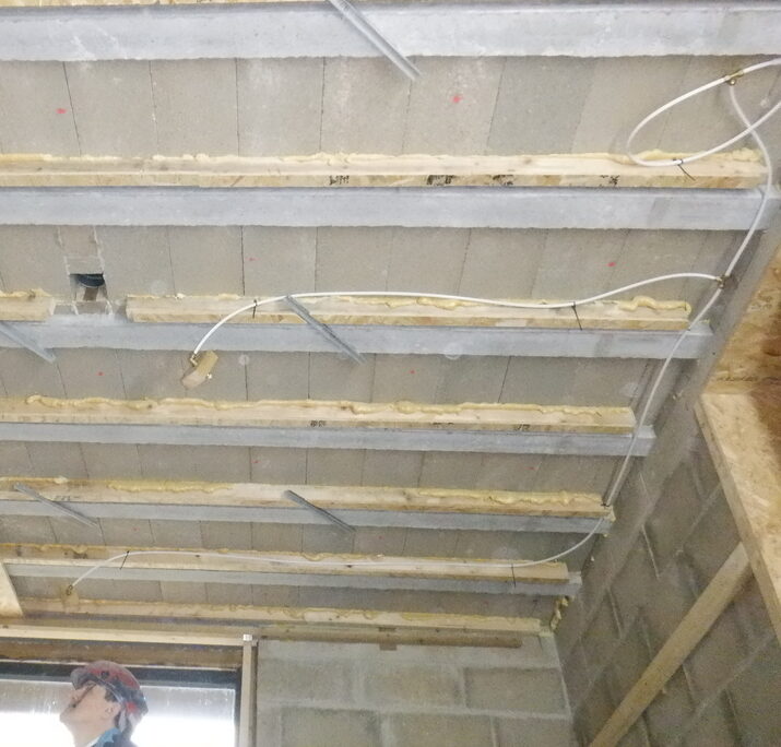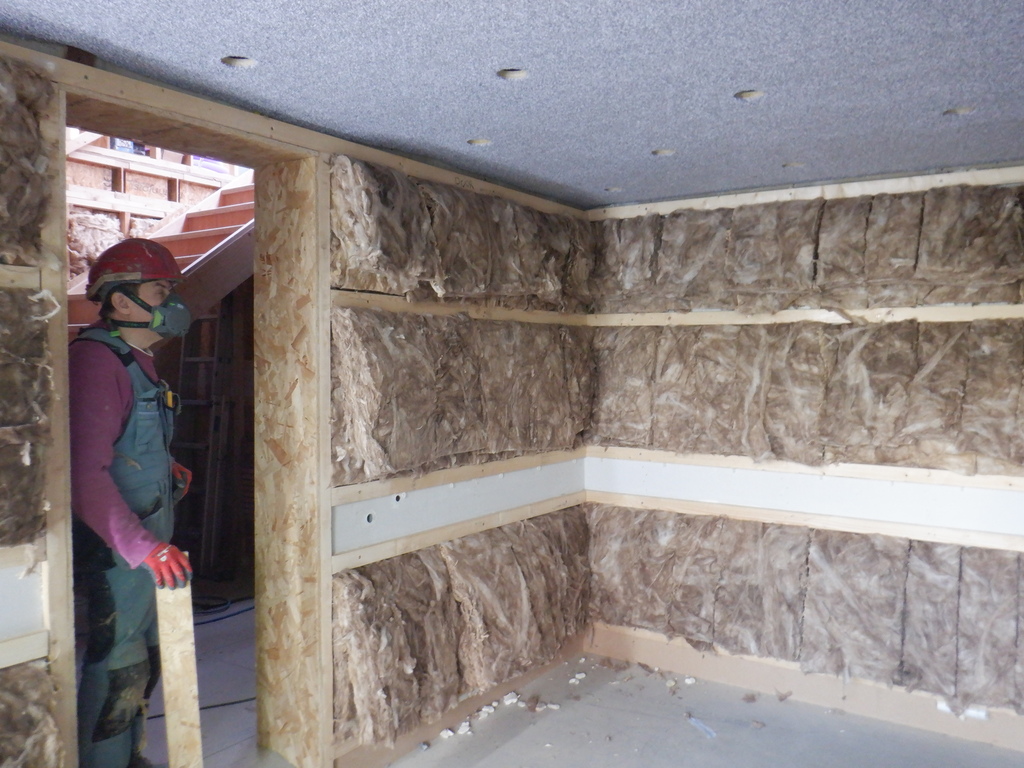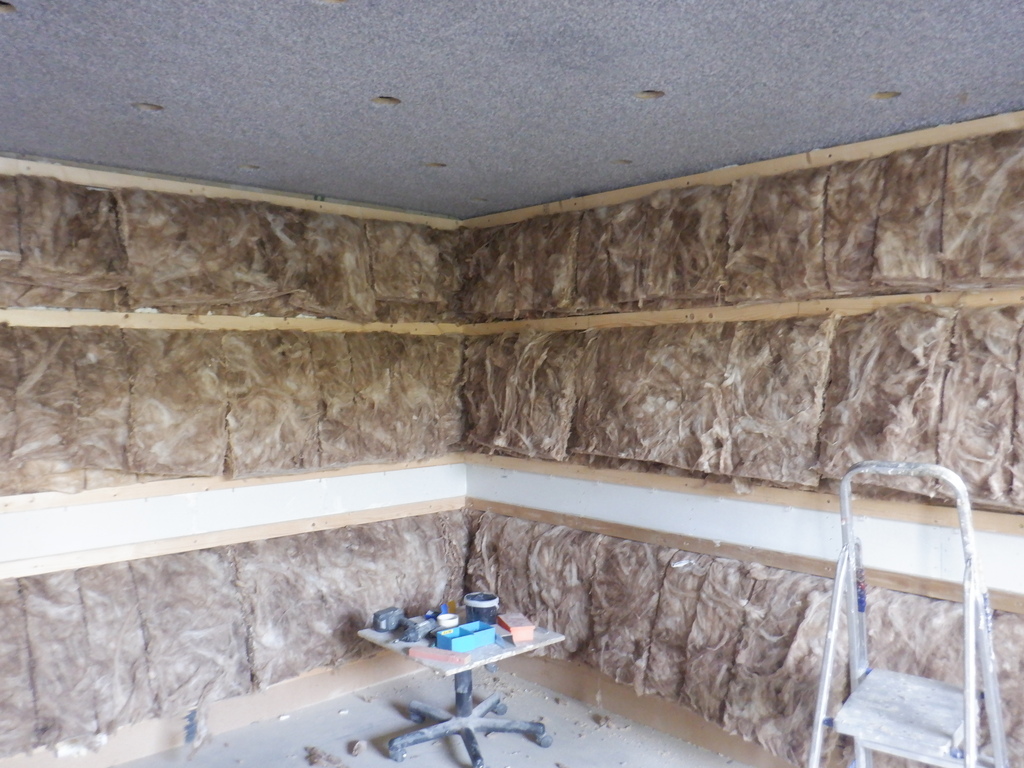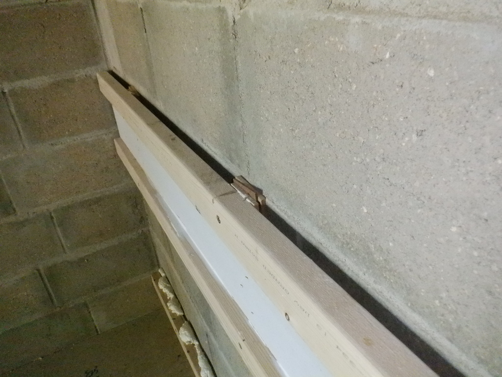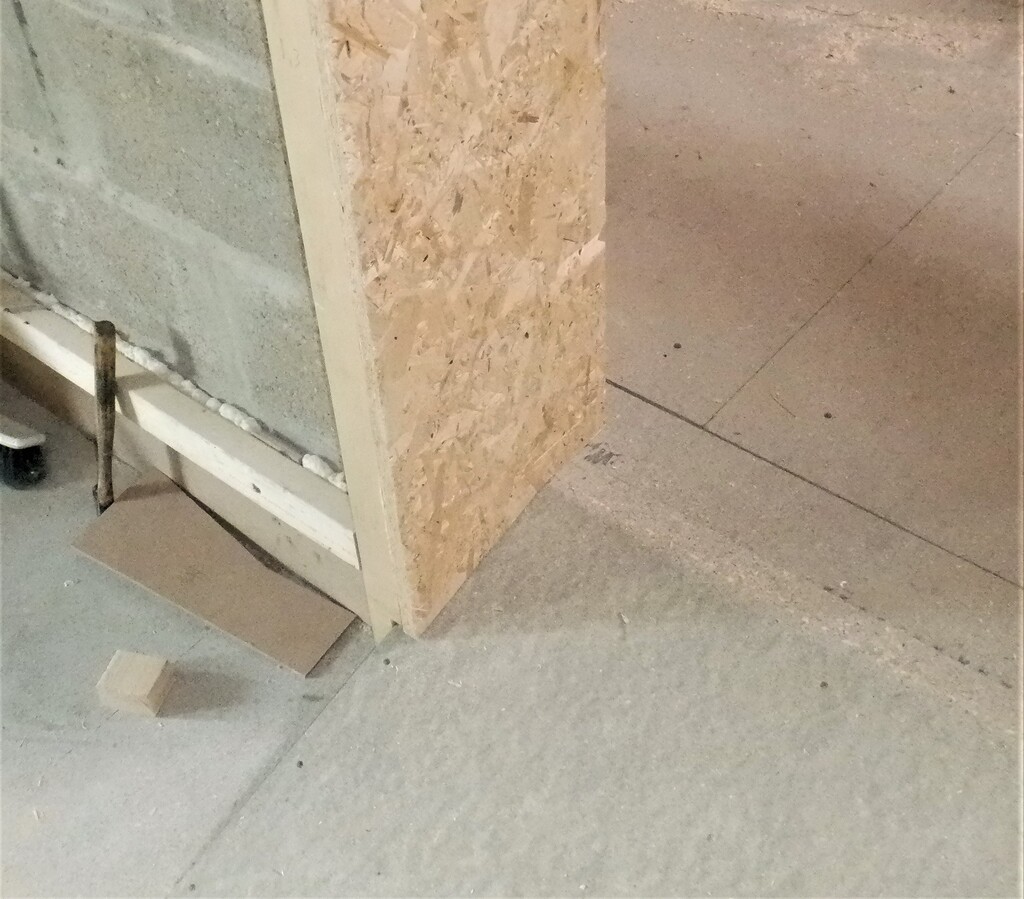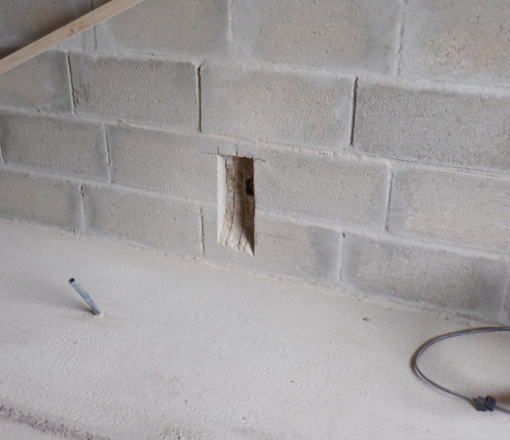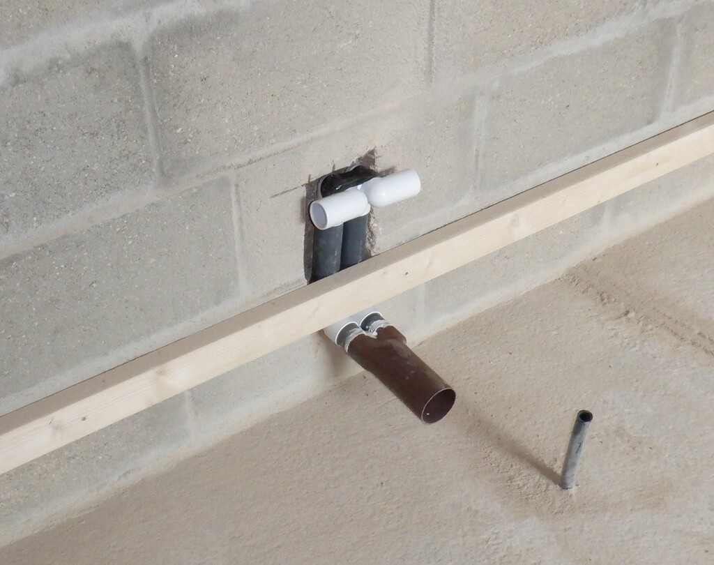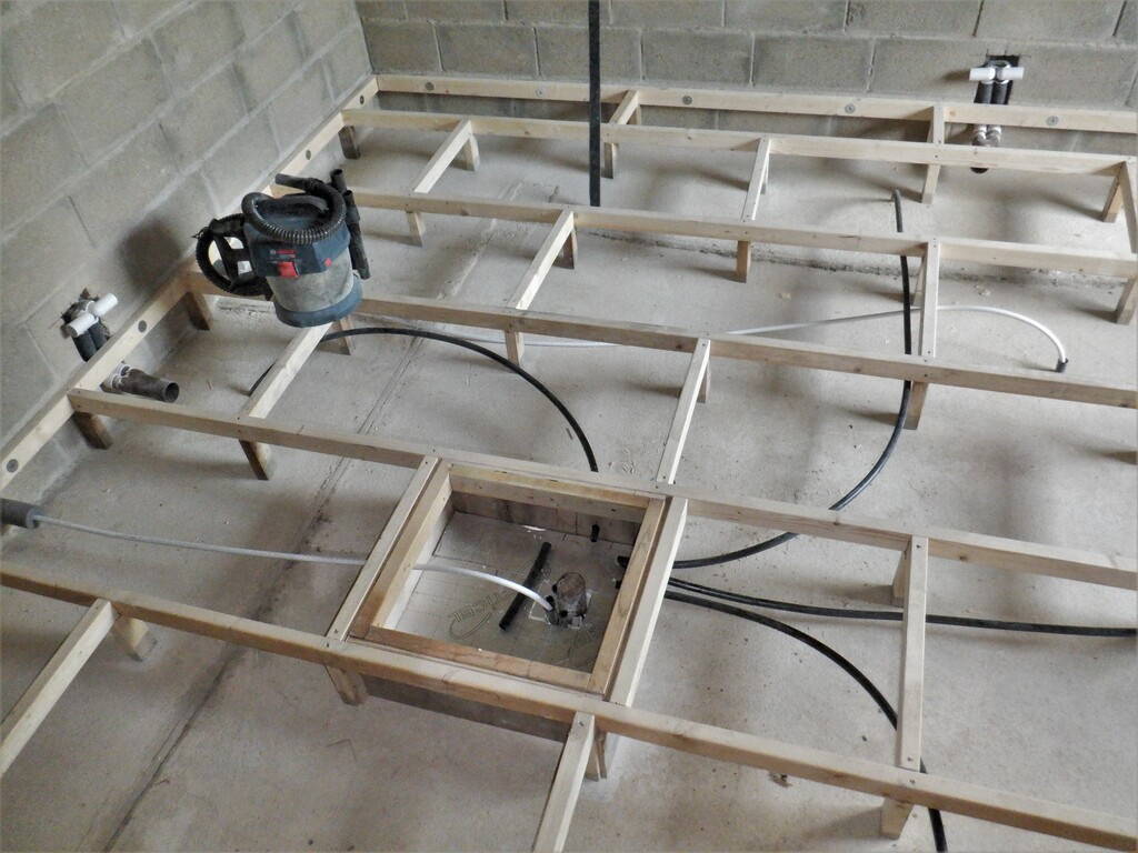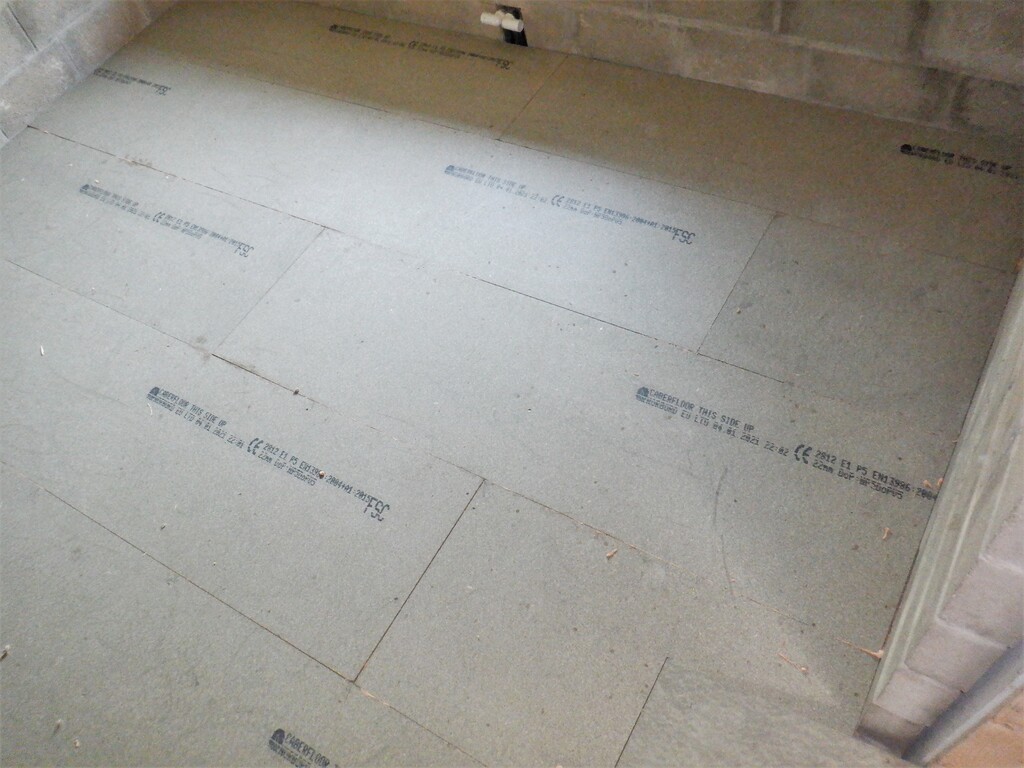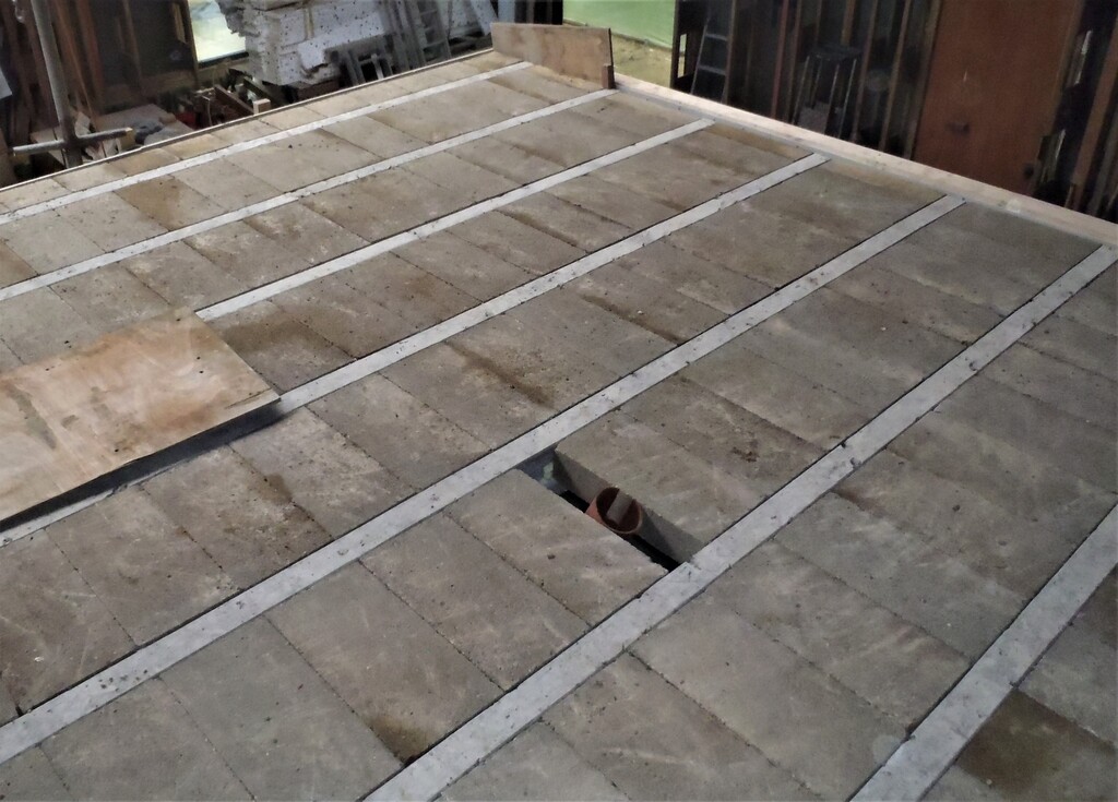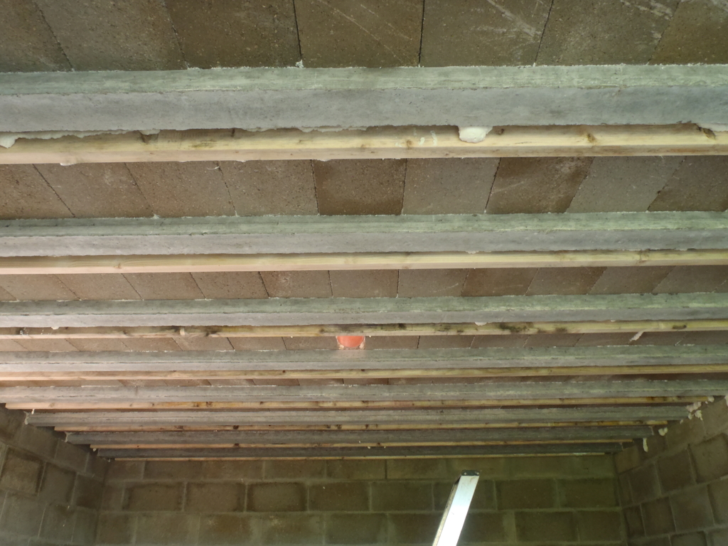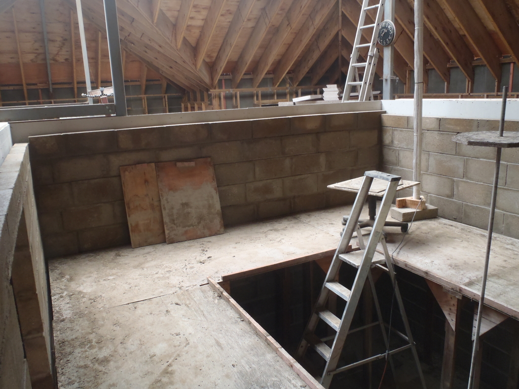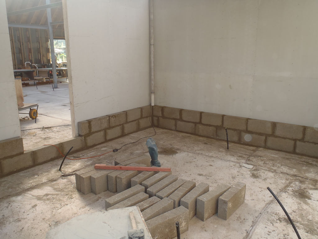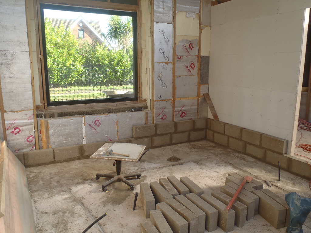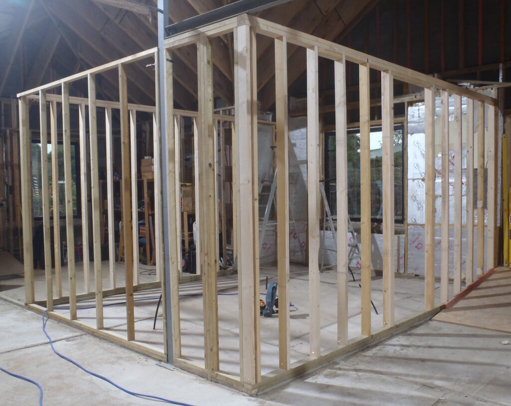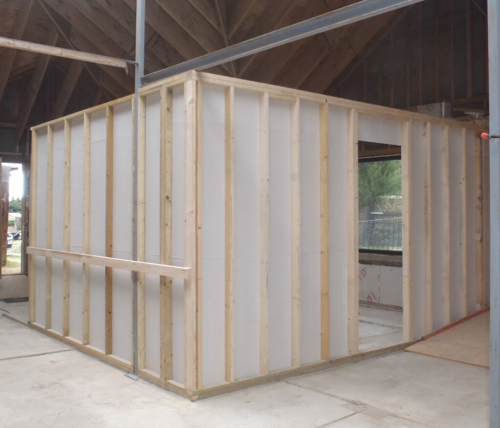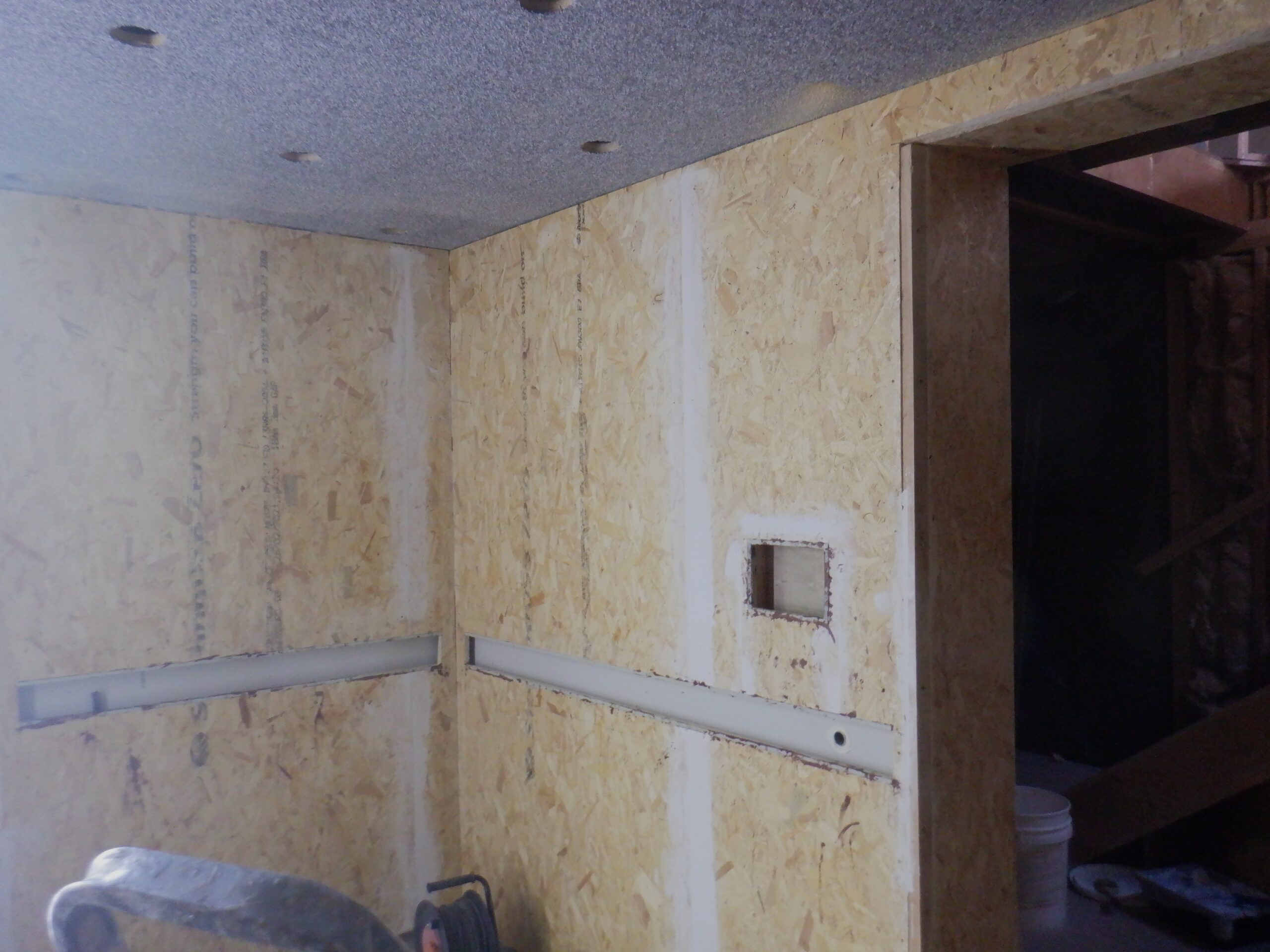
Utility Chennels cut out
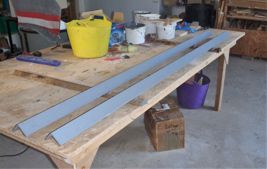
The next job is to trim a little thin recess, only 1mm deep and 12mm wide, on all the top and bottom edges of the Utility Channel and we then glued a thin narrow strip of steel. We had some old computer cases which were made of steel thin plates so we sliced that in our mechanical heavy duty guillotine machine and glued them so that we ended up with a general purpose magnetic surface so that we stick on our Oak covers into place, without having visible screws etc.
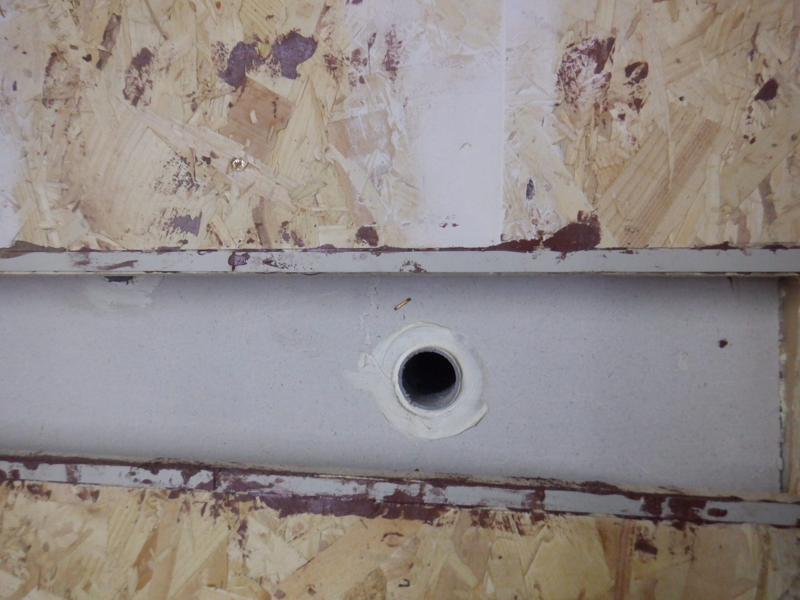
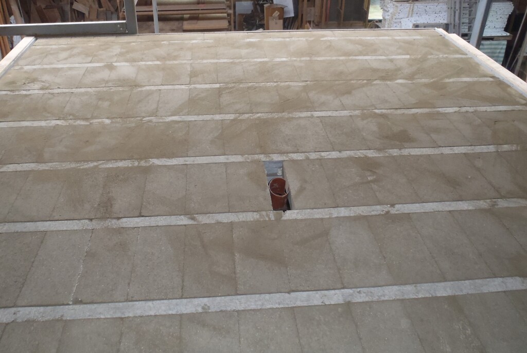
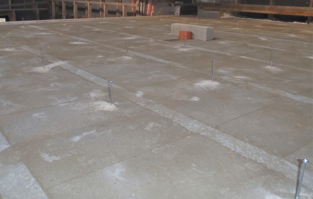
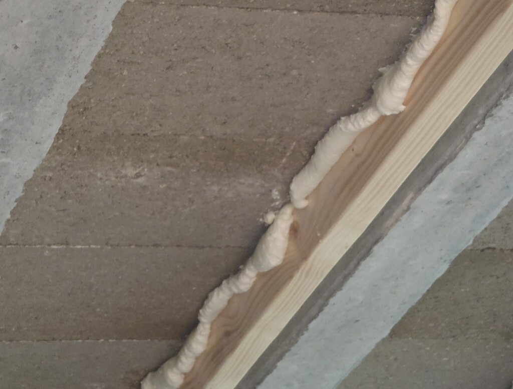
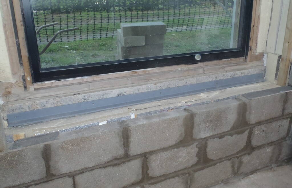
Metal strips glued in
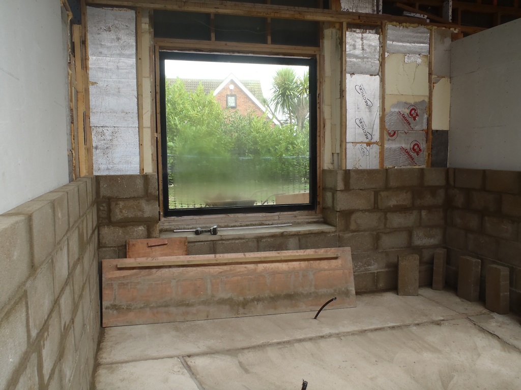
Oh yes, we rounded the edges of the window, the two vertical edges, using our largest round cutter so that the carpet can bend smoothly around the corner when it goes into the window hole. The horizontal top edge of the window was turned with a smaller radius cutter, just enough to get the carpet to bend around.
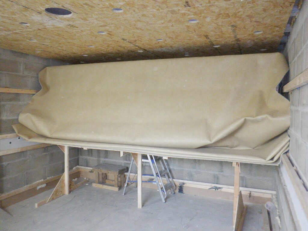
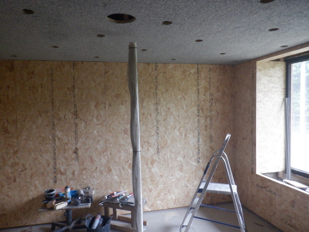
Now we were ready to start the next big task of sticking our carpets to the walls!
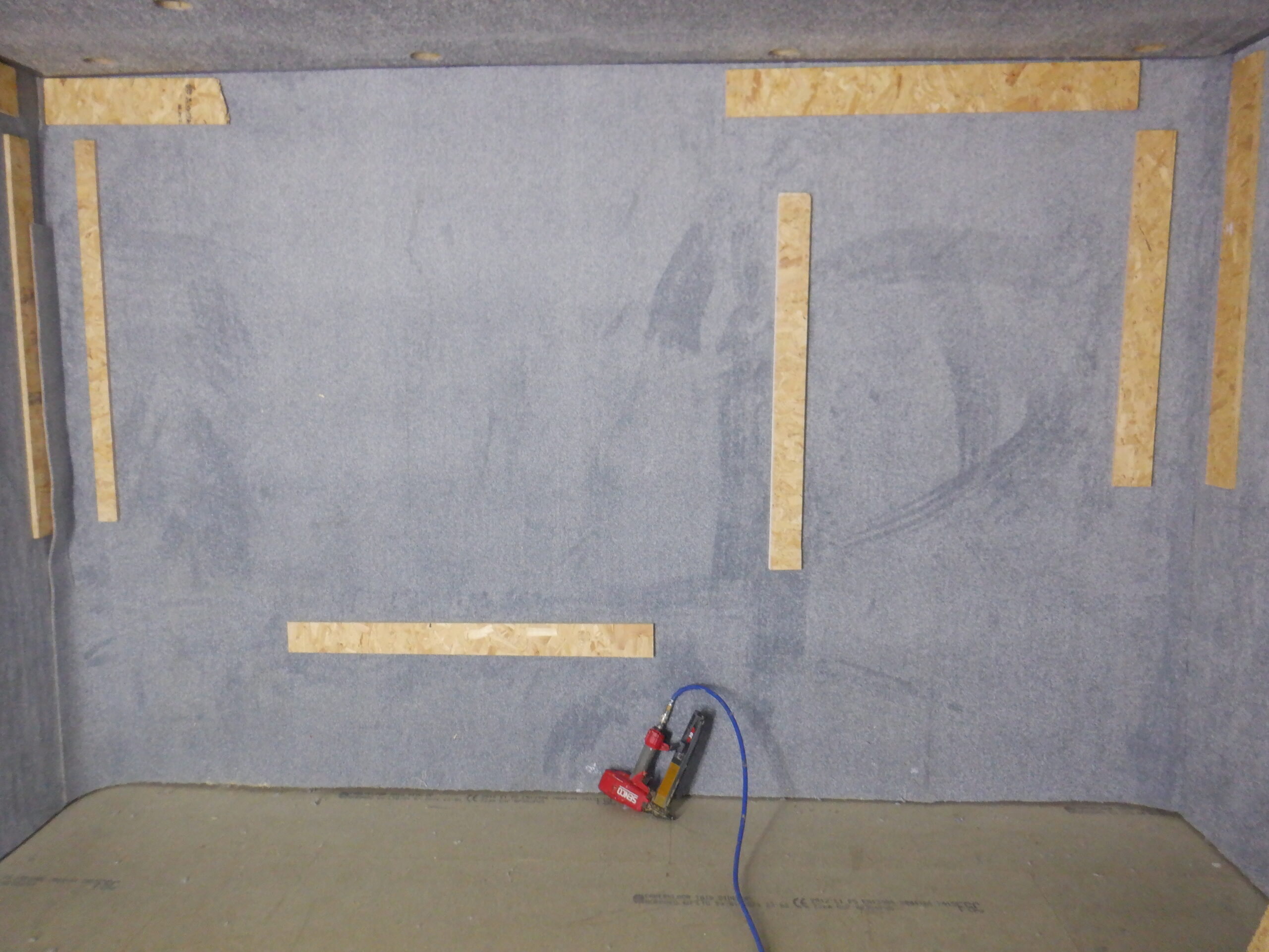
We started on the TV end of the room, the narrow wall, opposite the window and we got our 2.4metres by 4metres piece and then painted both the wall surface and the back of the carpet with the latex rubber glue. We had already determined that this glue works very well and it just needed to dry while the surfaces were pressed together. Another advantage of this glue, is that it dries fairly slowly and keeps moist, which gives us time to paint the two surfaces, but also, time to man-handle the carpet up onto the wall and move it around until we got it pressing tightly up to the ceiling. To help with that process, we stapled a couple of pieces of narrow strips of OSB boards on to the front of the carpet so that we had a good grip to help lift the carpet, but also to keep the carpet stretched out in a straight line as well.
We then temporarily stapled five more strips of OSB, to help hold the carpet tight to the wall and the glue. Fortunately, we had loads of these narrow strips that we had accumulated over the years and so we could use them to press the carpet to the glue. The staples were 35mm long and fired using our compressed air gun. Another thing we did at this stage, is that we avoided gluing the last right in the corners because we needed to be able to trim the carpet carefully right into the corners later on, after the glue had dried.
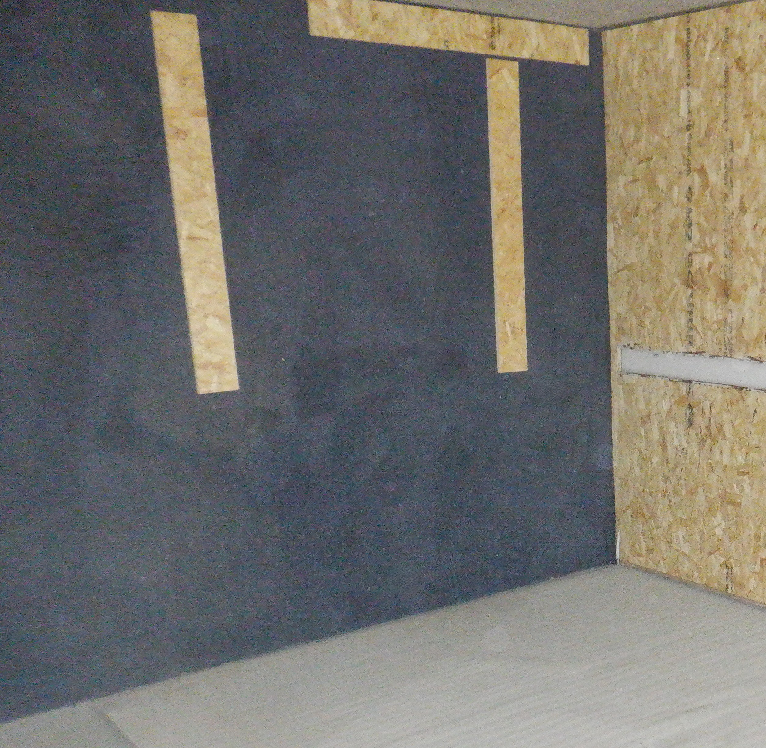
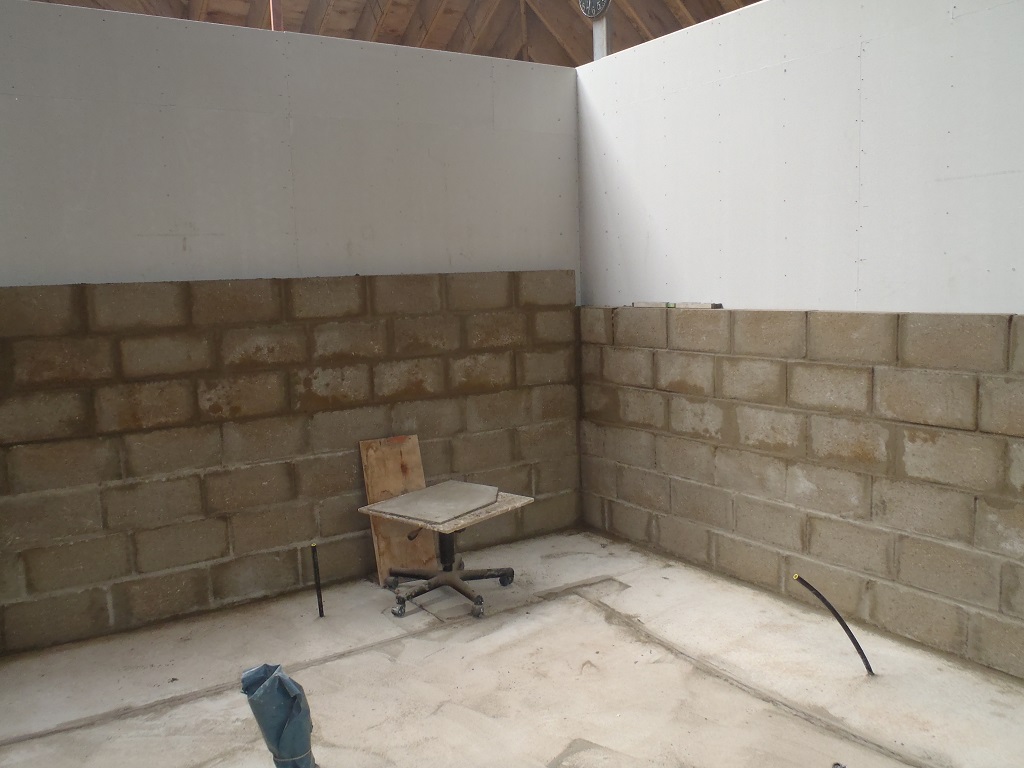
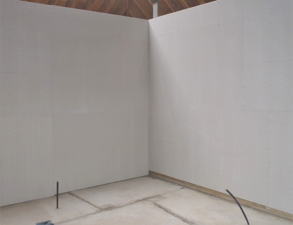
TV Wall carpet
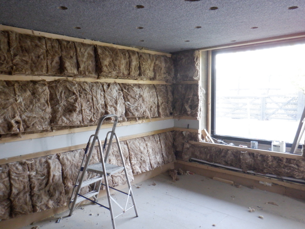
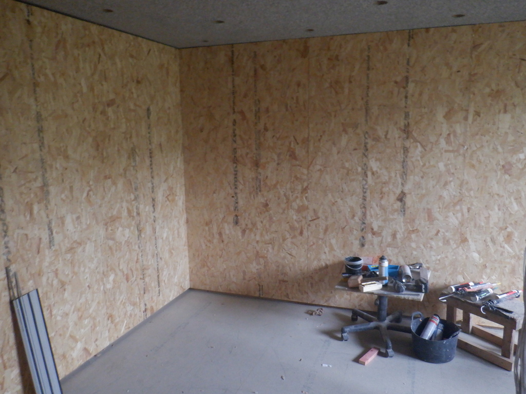
We then carried on with the next wall, the long wall opposite the door, which was a 2.4metres high by 5metres long piece this time. We proceeded like before but we discovered that this type of carpet, which has a woven backing, instead of the felt-like material the first piece had, we hadn’t put on enough glue to ensure a thorough contact area. This meant that we had to reapply extra glue around the edges, going along the top (near the ceiling) and also around the Utility Channel cutout as well, plus the bottom edge near the floor. We stapled on lots of OSB strips to clamp the carpet down so the glue had a chance to dry stuck together.
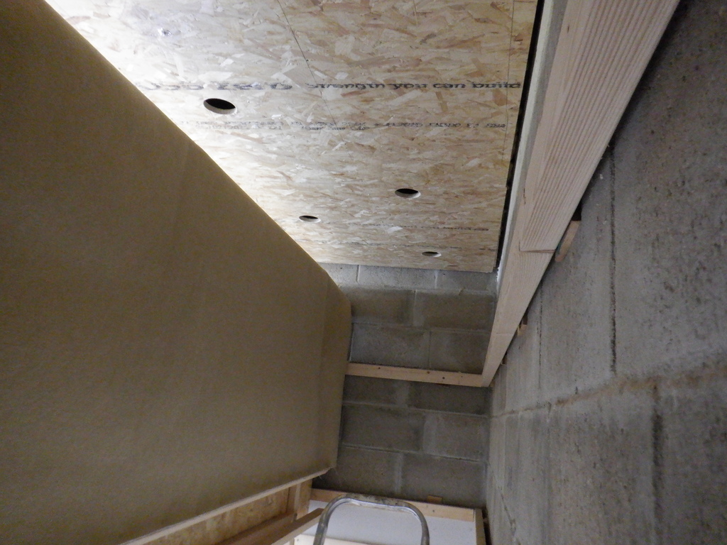
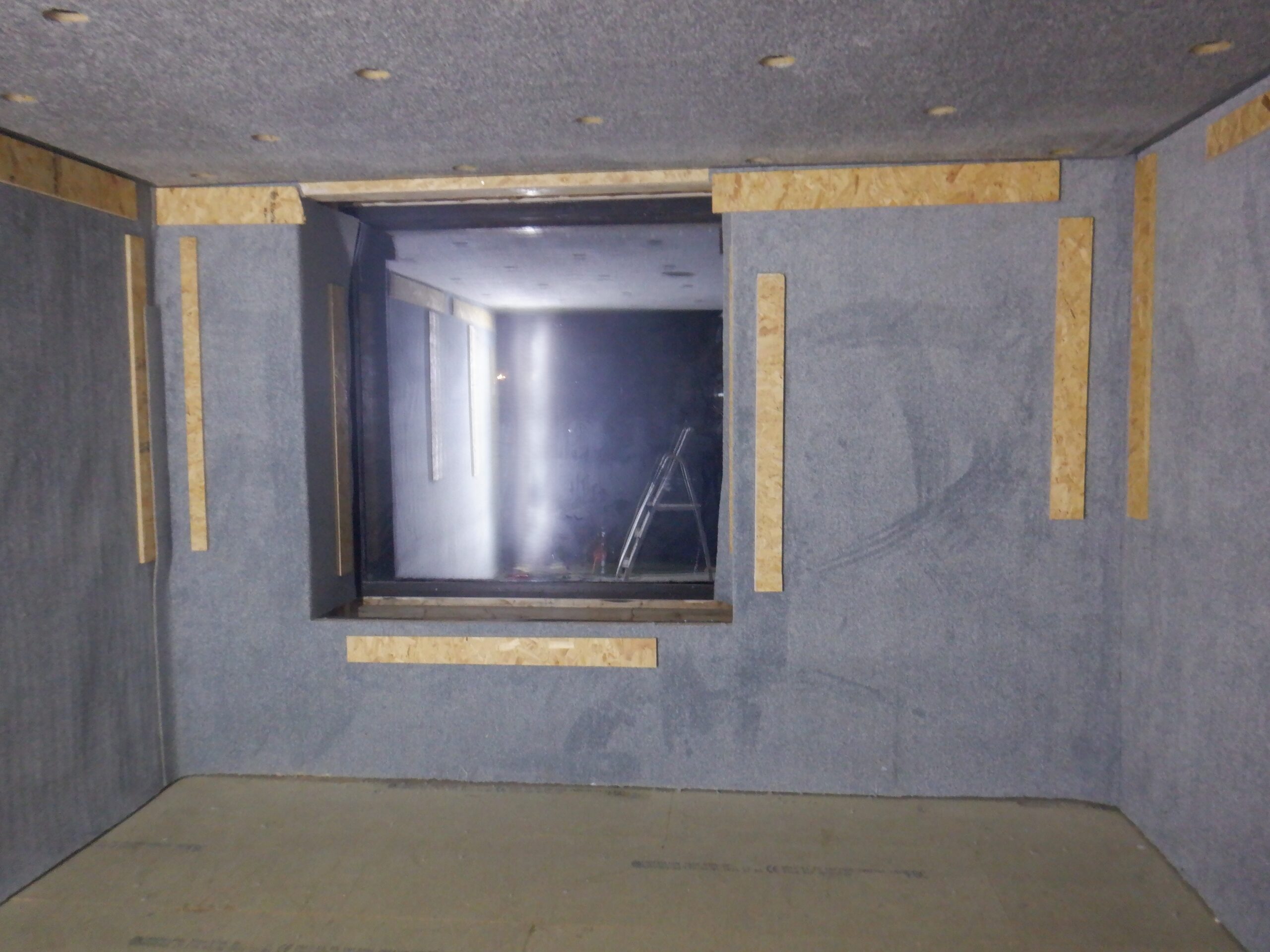
We then did the smaller portion of the wall to the left of the doorway, and remembered to put on more glue this time. It was easier to handle the carpet because it was in a smaller piece and we managed to get it up with little trouble. We repeated for the other side of the door and then did the section over the top of the doorway. We even put a piece of carpet on the ramp going down into the room! Now, we turned to the last wall to do, the Window wall. This time, it went up in one piece because we wanted the carpet to be continuous underneath the window sill. We carefully cut the carpet along the bottom edge of the window and then bent the carpet around the corner to do each vertical sides of the window. We took off the excess and glued these flapping side bits into place. Finally, we had a piece of left-over to go along the top edge of the window and that got glued down as well.
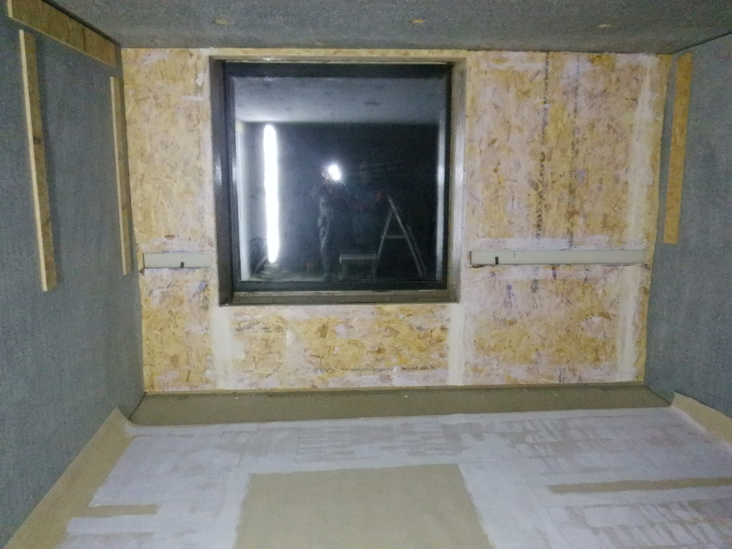
Carpet for the window wall glued
Windows wall covered
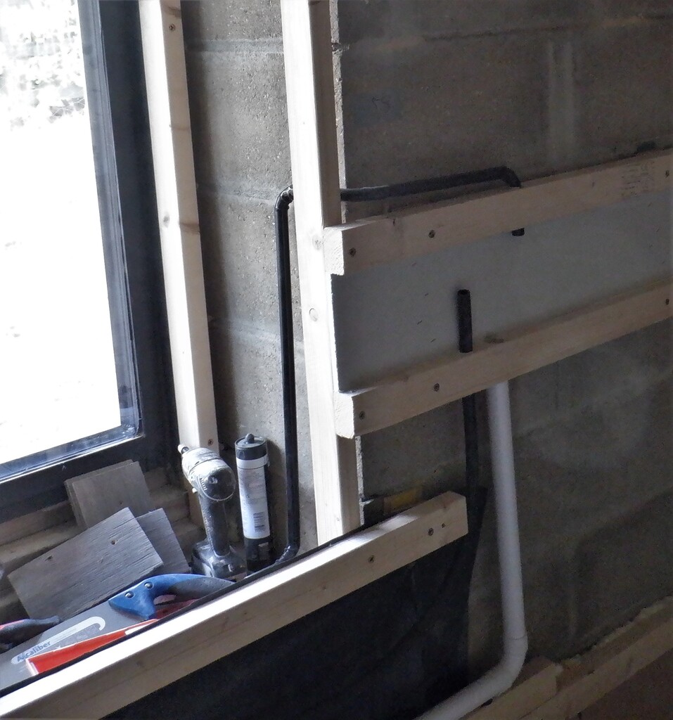
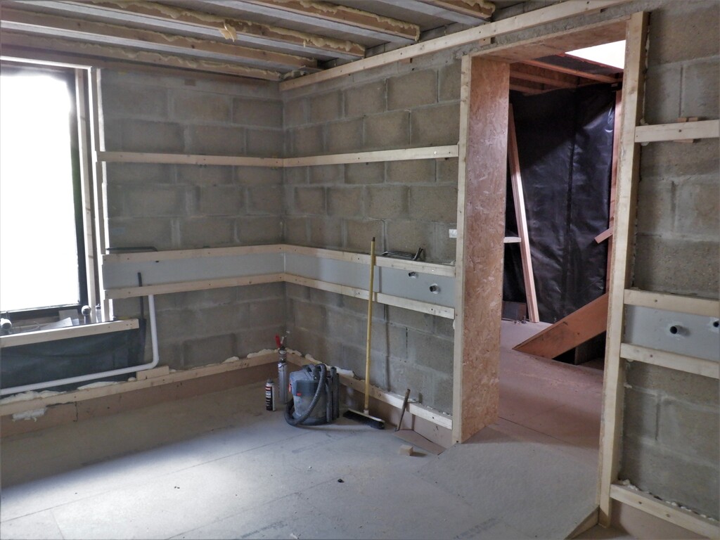
Trim out the window
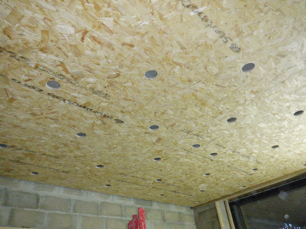
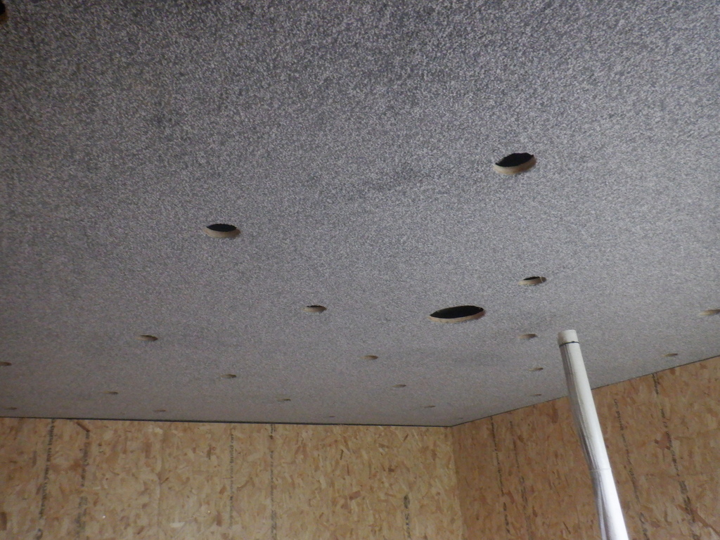
Next, we installed ten round lighting units up in the ceiling, plus two odd square ones we had lying around, to populate twelve of the holes , four rows of three lamps. A light switch went into the Utility Channel near the door, and then put eight double sockets distributed around the room as well. We used pieces of 11mm OSB boards to make the covers and got them magnetically attached over the Channel. This is a temporary measure but we will replace with proper Oak covers later on.
We used two 3mm thick by 10mm diameter magnets, superglued together to form a 6mm single unit. Then we put four of these magnets in the four corners of a cover where there was only one mains socket in the cover, six of the magnets for a two set of socket, and eight for the last cover that had two double sockets plus the light switch. We discovered that just having four magnets was not quite strong enough to reliably hold the cover in place, especially after the electric cables were threaded and screwed into the back of each socket as well. Magnets are very good, visually speaking because we can avoid unsightly screws etc. but unfortunately, the initial experience is suggesting that we would have to add a dozen more magnets for those covers that have a mains double socket in them, especially if you tried pulling a plug out and accidentally ripping the whole cover off as well. We will have to explore this further, and maybe come up with a different method of attaching these covers without visible screws.
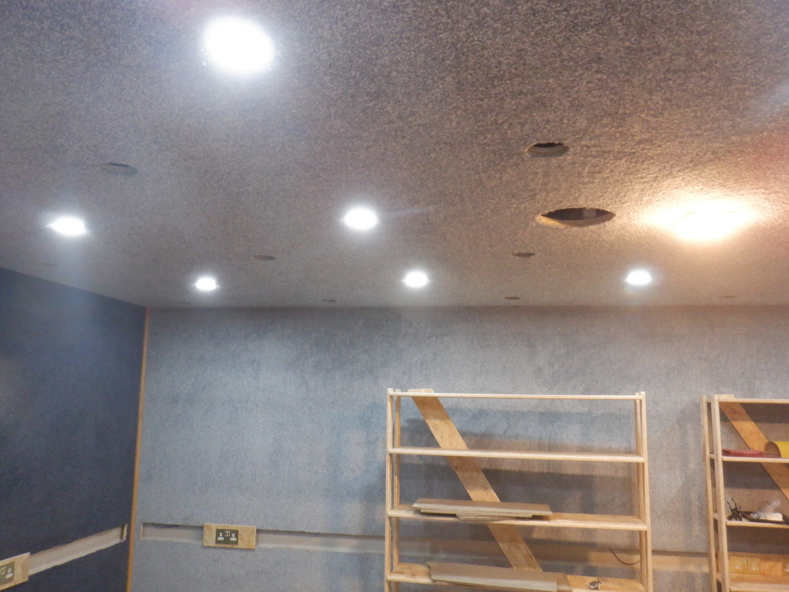
Temporary Lights
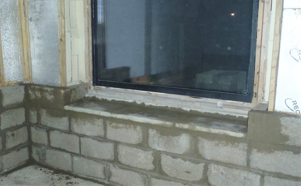
We then made a window seat, again a temporary one so that we had a neat cover over the empty void in the bottom of the window. A useful place to sit on now.
Because we had decided that this room, the Entertainment Room, is going to temporarily be the needlework room, to allows us to sort out things like curtains etc. So, towards this aim, we created a large work table, 8foot by 4foot and standard dining table height of 720mm high. We used one of our 12mm thick MDF boards and glued a circumference of 63mm CLS planks around the edge, with an inch gap. Then, put on four legs.
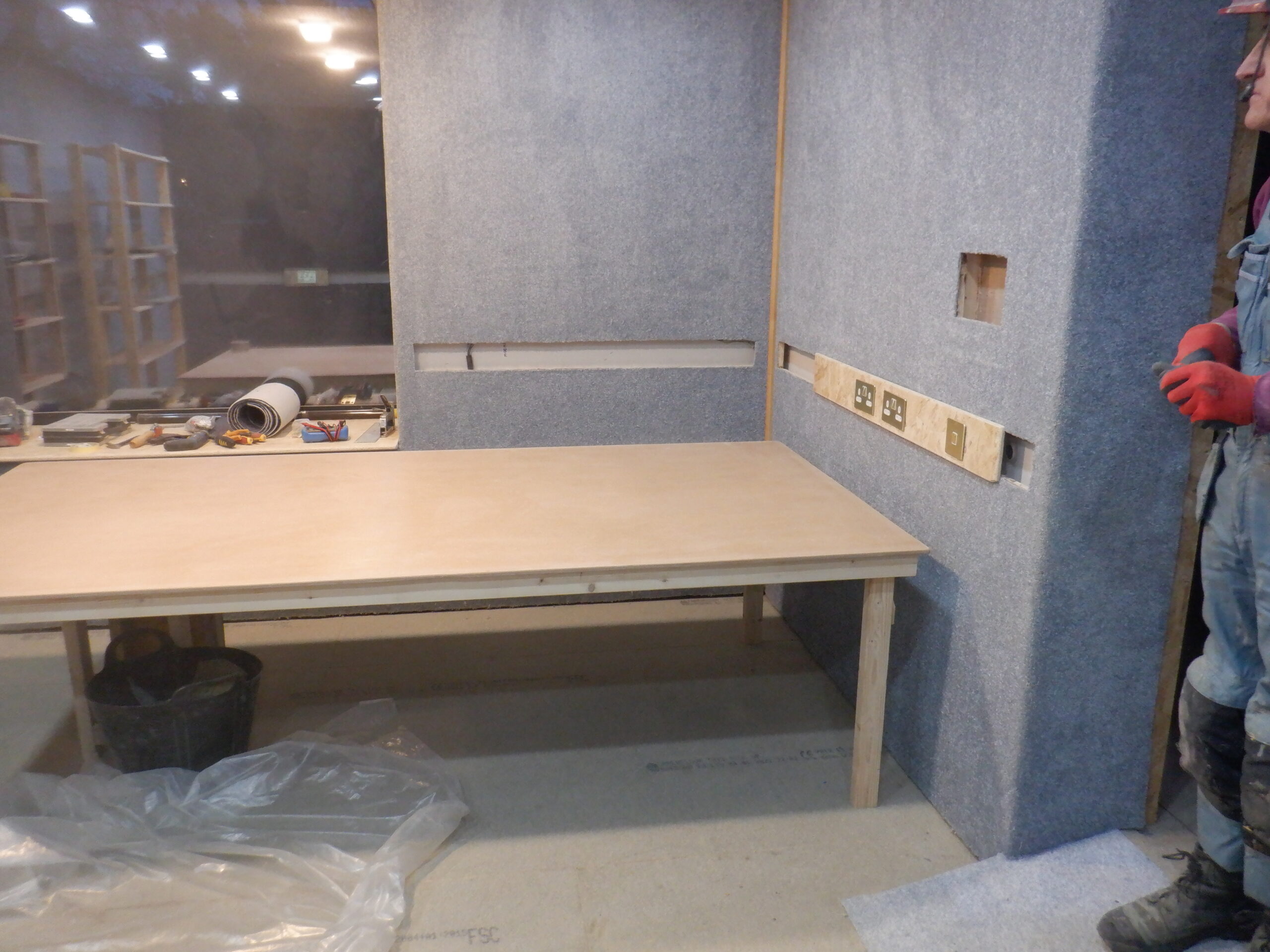
Table
Then, we created two sets of shelves, each one having six shelves, measuring 300mm deep and 1220mm wide. We managed to use two sheets of our 18mm thick OSB boards and sliced it up into twelves pieces and then slice eight 50mm wide longer strips to serve as legs. We ran the router over all the pieces, to chamfer the edges, to remove splinters and make it smoother. Both were assembled so that each shelf had a bit over 300mm gap between each self. Then, both the shelves and the work table, plus also, the window sill seat, got a coat of varnish, to make sure that all the tiny splinters are glued down and after rubbing with some sand paper, it is all nice and smooth.
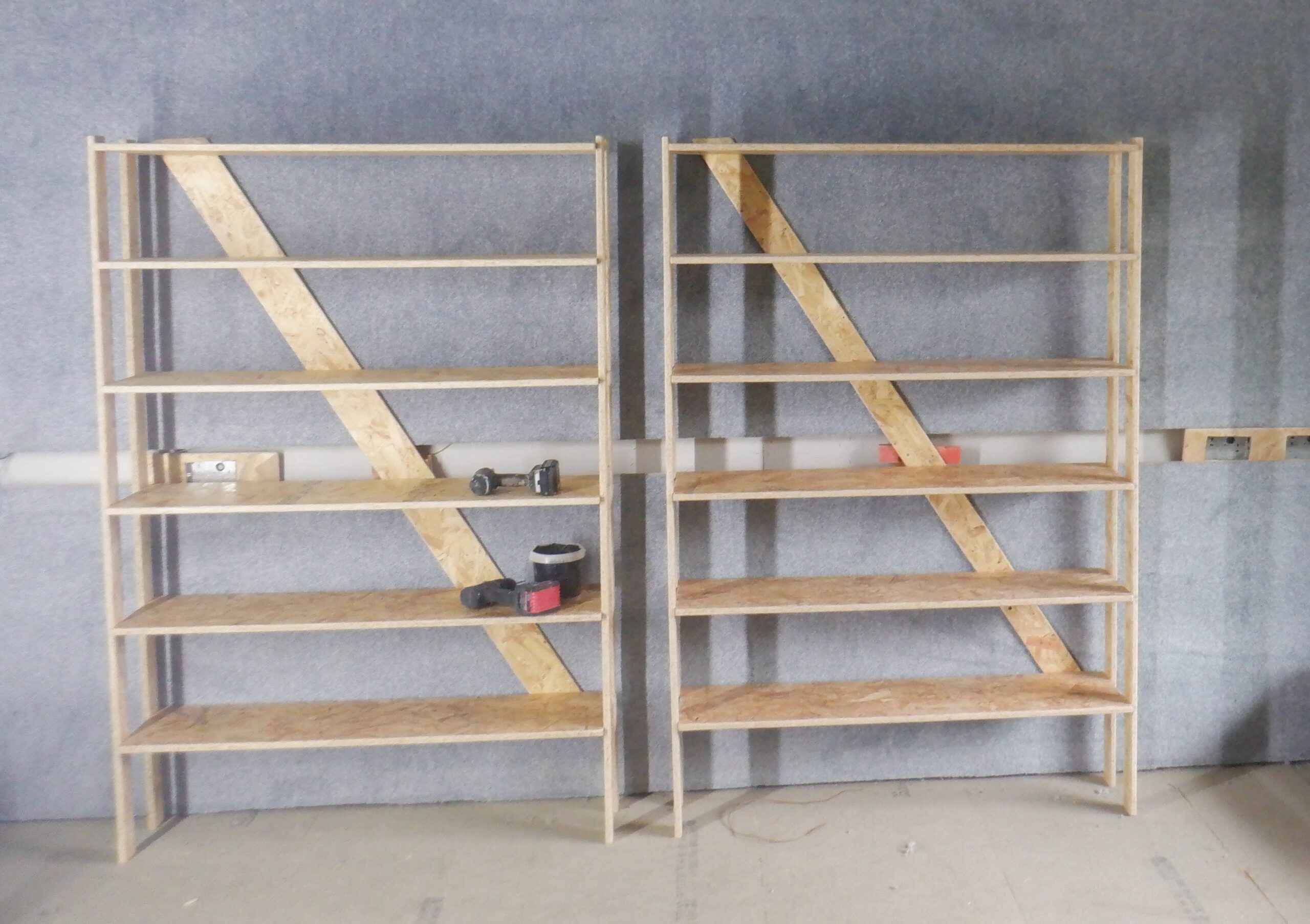
Shelves
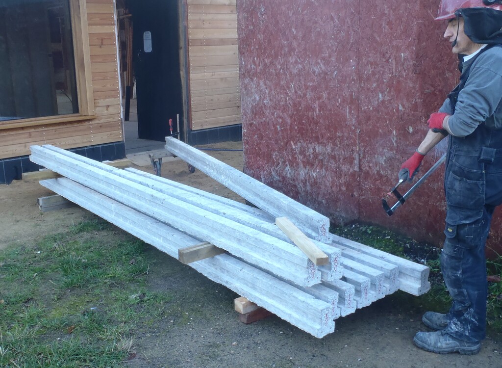
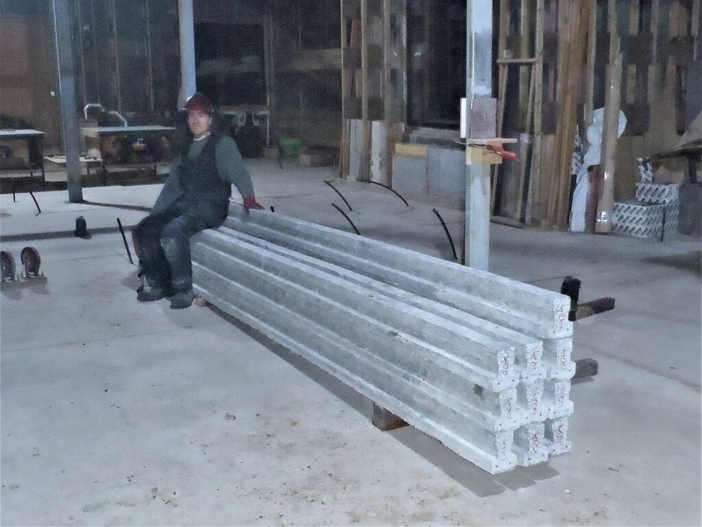
Next, we created our special sound deadening door. A very heavy door, made up with 30mm thick of cement boards as the core, covered up with 9mm hardwood plywood sheets. To maximise the strength of the whole thing, we found a piece of thick Oak plank, with minimal knots in it, measuring 2.7metres long and 150mm wide. It is 65mm thick. We established one straight edge by using our track saw and then planed it flat on both sides, ending up with a 48mm thick plank. We then, sliced it into two narrower pieces, with a 15degree angle down the middle. The last step in working these pieces of wood, is to trim off a recess on both side, to form a 30mm thick “tongue” which matches the thickness of the cement core so that the plywood covers can overlap both the cement core and the two Oak vertical edges. The cement core was built using three layers of small left-over pieces of 10mm thick boards, arranged so that every piece overlapped each other with plenty of surface. We used an epoxy resin glue to ensure a very strong joint between every piece. Because of the random nature of all the smaller pieces, the resultant “core” is rather misshapen but we knew that we wanted to slice the core down to a precise size later on, including putting a 15degree angle on the narrow top and bottom edges as well. Finally, we assembled the two Oak strips and one of the plywood fronts, used PU construction glue and a dozen screws to anchor the Oak and plywood together. At this point, we mounted the hinges and mounted the partial door into the wall for testing purposes and making sure everything is ok. Now, turning it over, we then used plenty of PU glue all over the back of the plywood and very very carefully lowered our concrete core into the middle. Then, the second plywood board came in on top, again, with lots of PU glue spread out evenly across the cement surface and screwed the plywood down tight on the Oak edges too. We loaded seven large concrete blocks on top to pressurised all the layers together and stop the glue pushing the layers apart.
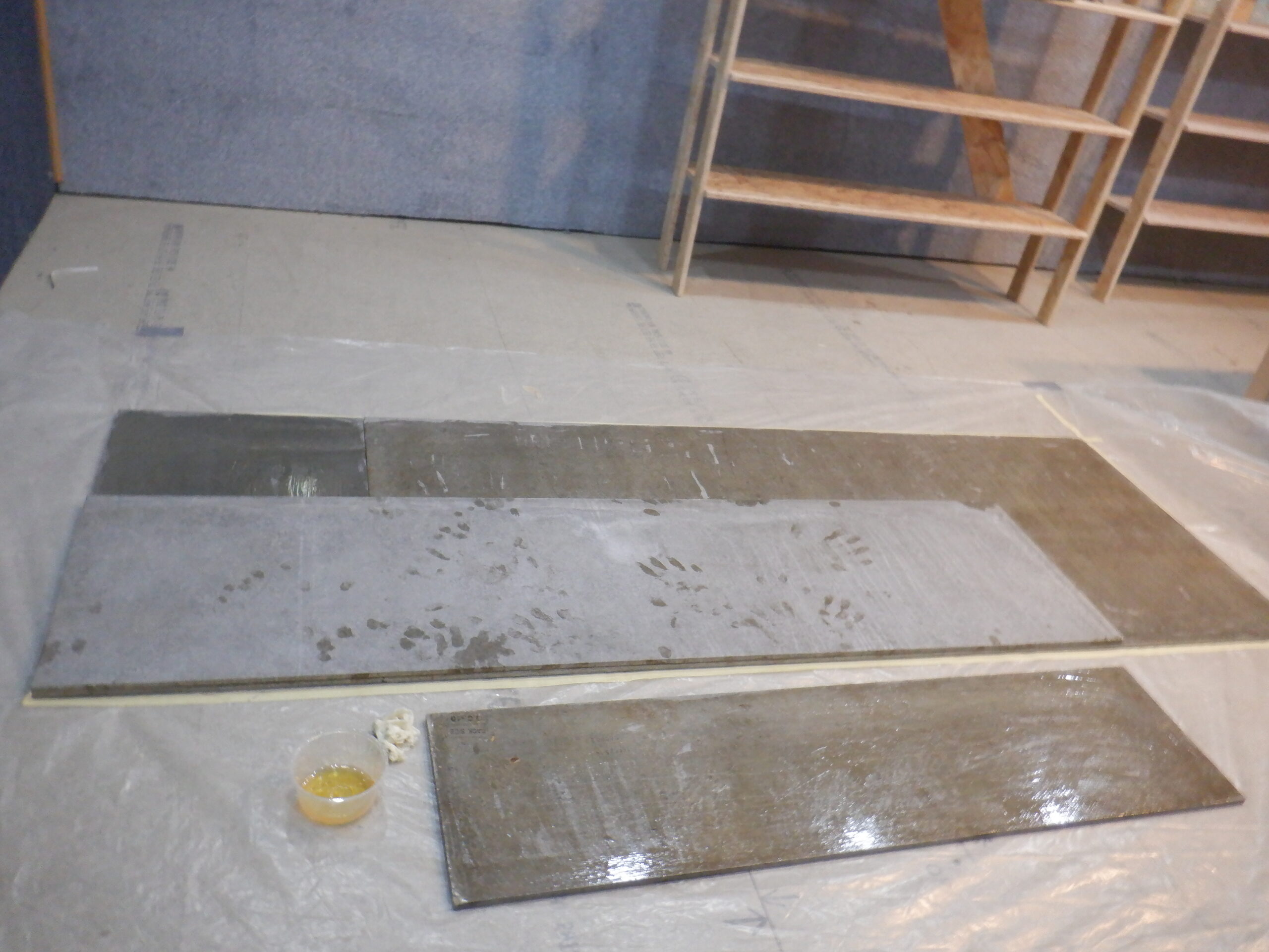
Glueing Cement board core
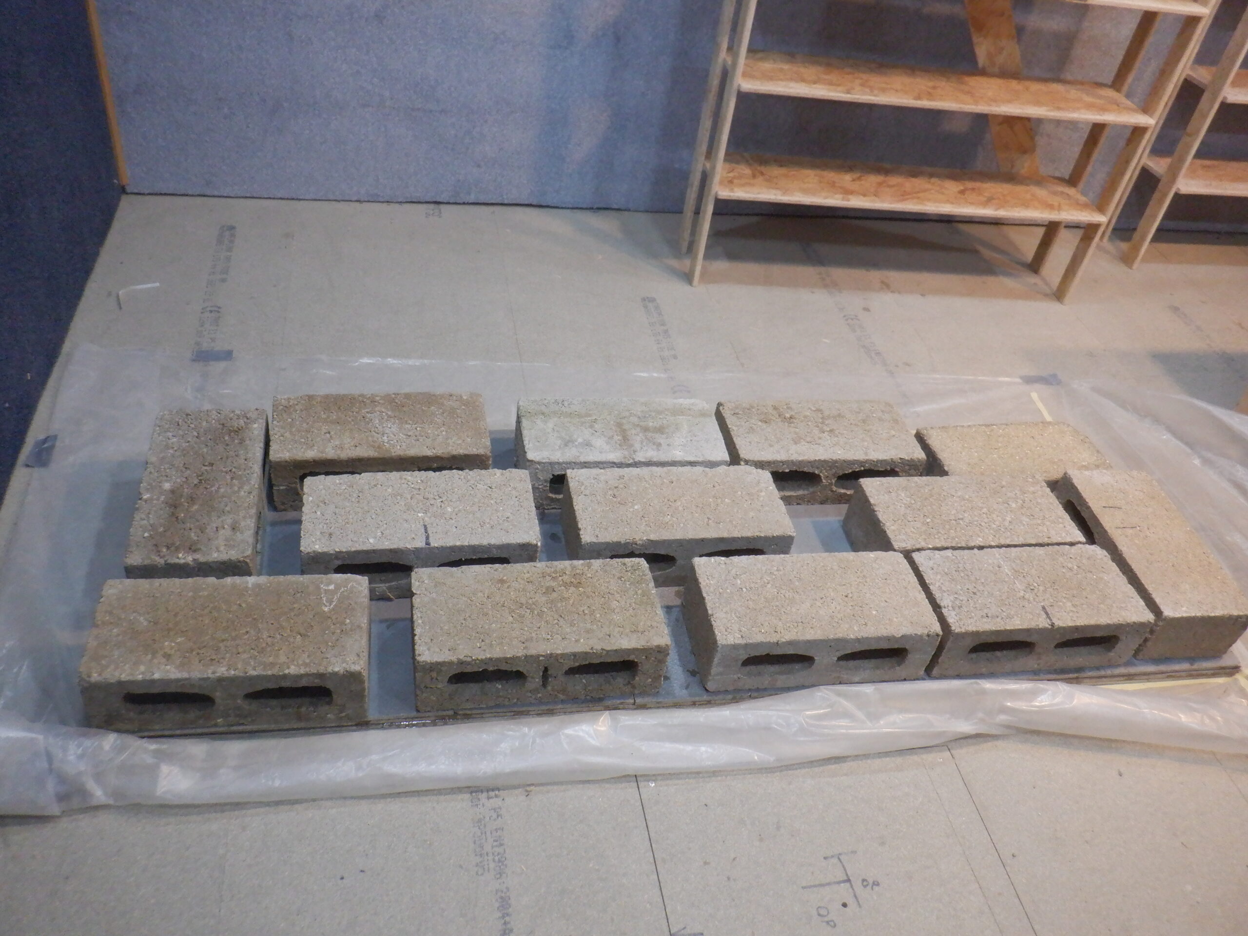
Holding layers while they set
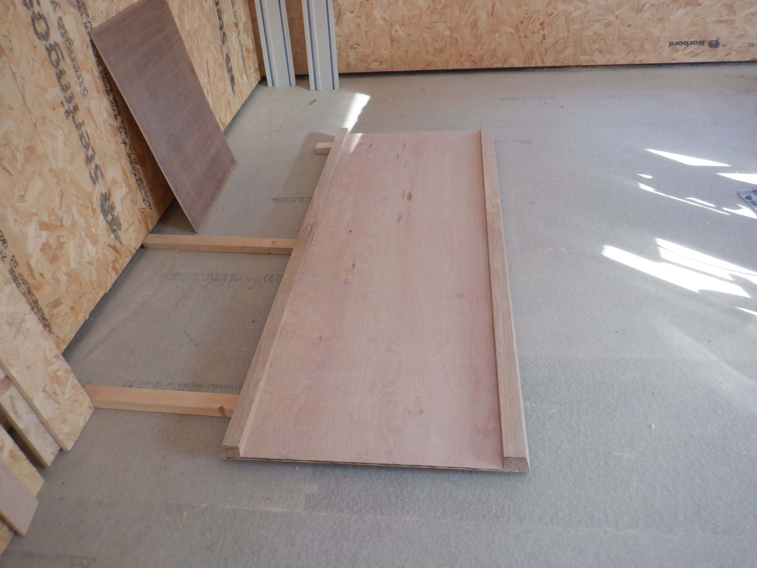
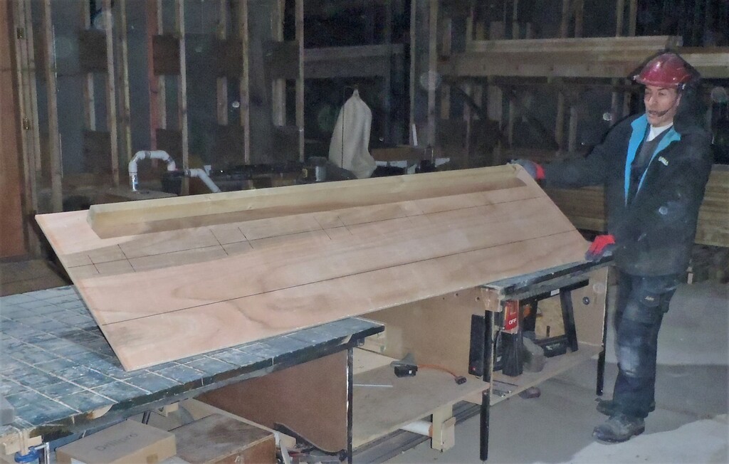
Door Outer part
You might be wondering to how heavy this door is??
Well, we got our bathroom scales and HAULED it up onto it .. ..
95kg!!
15stones!!
O boy!
This is why we are having four ball bearings hinges!
They are rated at 120kg for three of them so we thought we better put in that extra one, just to be on the safe side, plus also, the hinges comes as a pair so we didn’t want to have one left lying around.
It is recommended that one puts two hinges at the top of the door, one in the middle and one near the bottom. The double set at the top has to take a good portion of the weight as the door swings out. So, we mounted the hinges to the door frame first, cutting little rectangles of carpet away so that the hinge can go flat solid against the oak strips we have previously inserted into the wall structure. Each hinge has four screws in each half so there will be a total of 32 screws holding up this 100kg door!
Now the next trick was to move the door itself and walk it up several layers of pieces of board, and sit it on the top layer which has two air cushions underneath it. We could then squeeze the air bulbs to pump in air, which in turn slowly lifts up the door so that our hinge screw holes can line up with the holes already in the door, from our earlier quick test we did before we put in the heavy cement core. We got it all screwed in and let go! The door is swinging nicely and it goes home very nicely too.
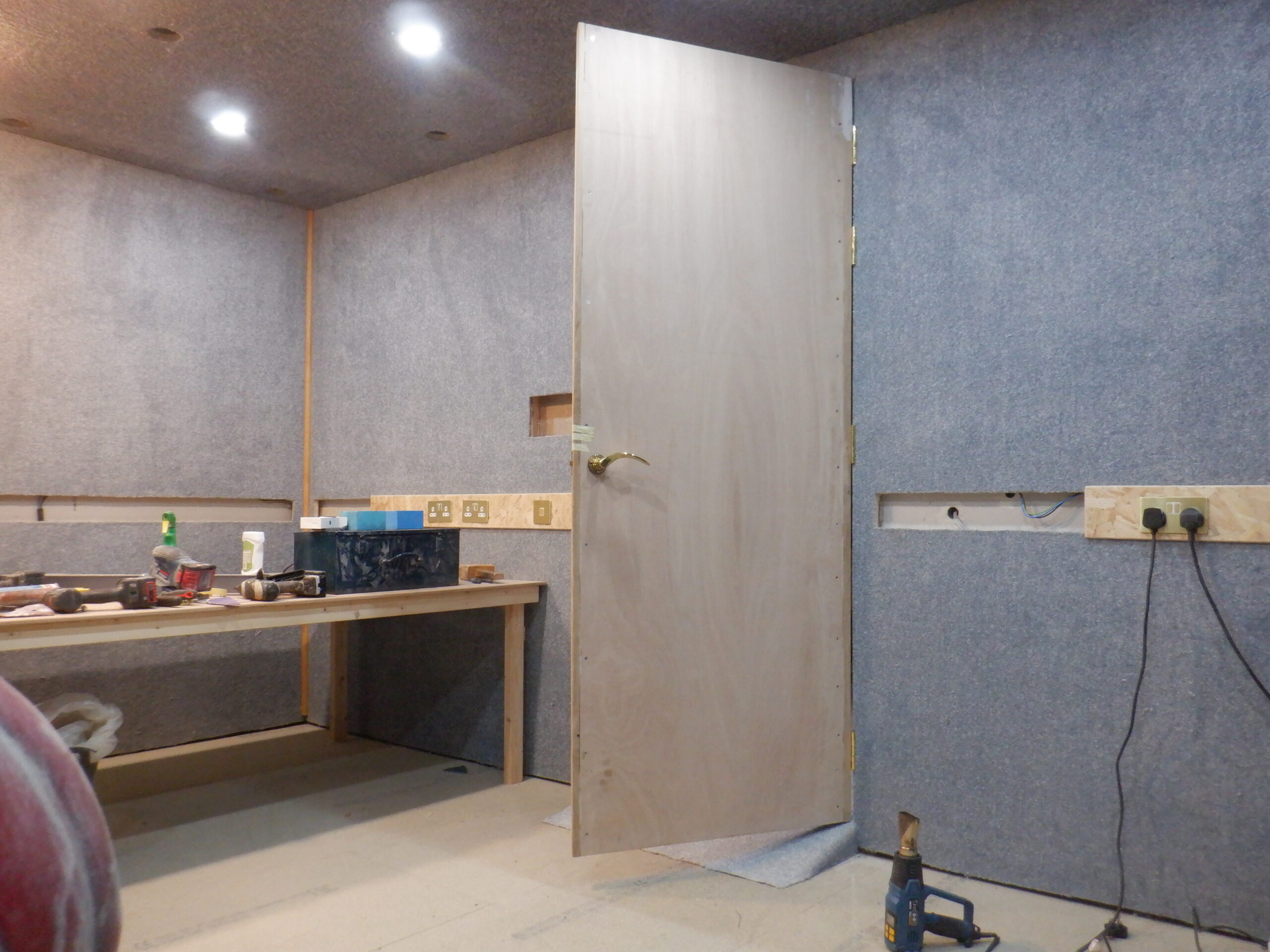
Door installed
Next, is putting in the latch mechanism and the handles. We had to find a longer square metal bar because our door is 50mm thick, especially with the carpet on it as well. Talking about the carpet, we decided to cover the entire door in cloth and carpet materials, to hide the various construction joints and materials, to end up with a smooth single texture on one side, using two fleece blankets, and three left-over pieces of carpet on the room’s side of the door. The fleece material was wrapped right around the whole door and stapled into place on the carpet side, and then we put on the carpet, to cover that up. But, the carpet had a ragged edge as well, so we went off to find some more Oak and create some thin slightly curved strips which we mitred around the edge of the door, to hide all the ragged edges.
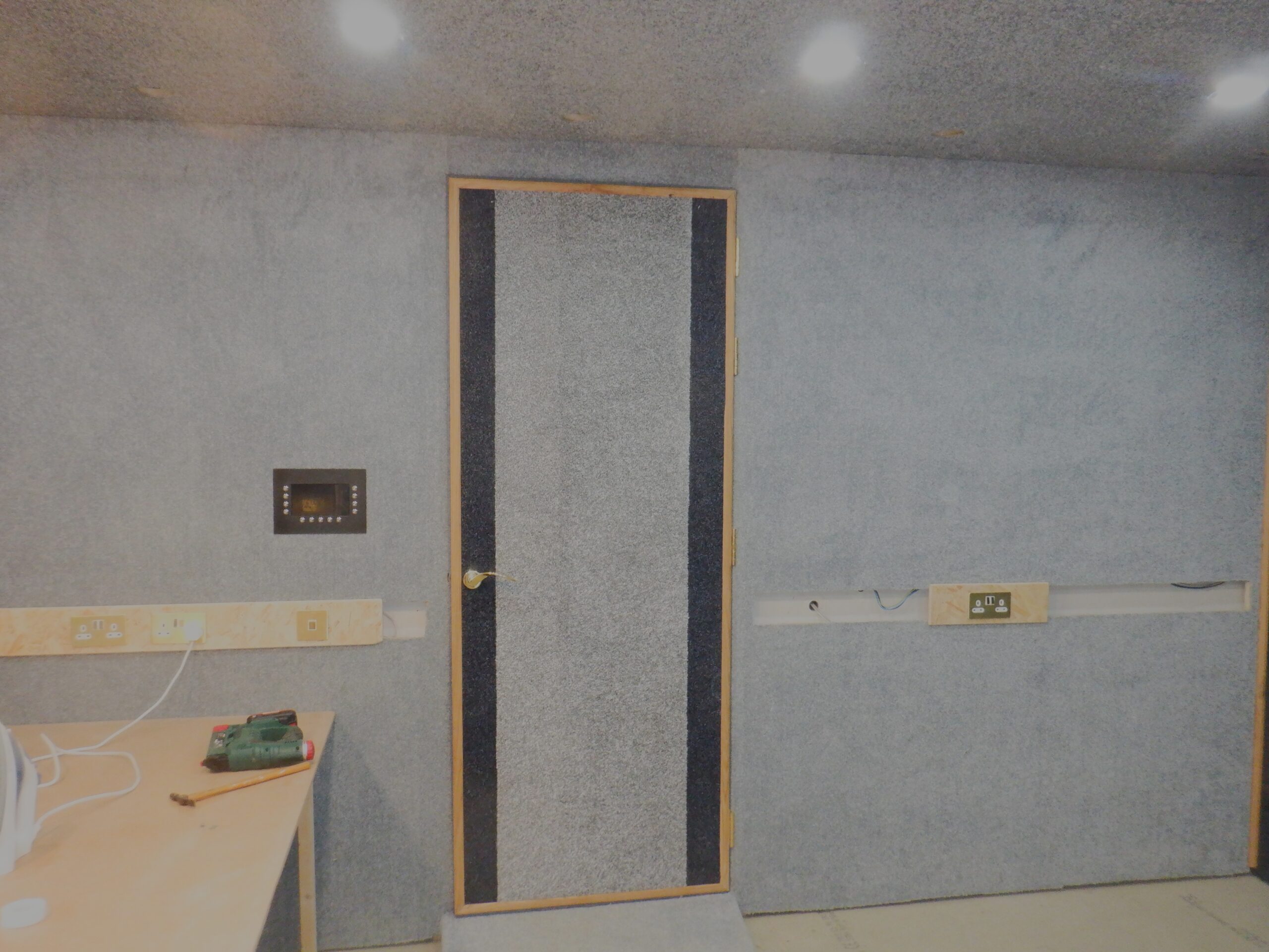
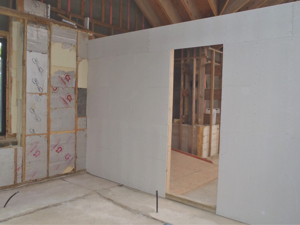
Door Wall Finished
That is one half of the doorway done, the main sound proofing door which opens into the room and is flush up again against the rest of the wall. There will be a second door on the Hall side of the doorway, to provide a second sound barrier to reduce audio leaks. We did some tests (once we had installed some speakers etc.) and the loud music could be heard quietly when one stood near the door but a lot quieter around the corner. Which is not surprising because the main room has 100mm thick concrete blocks and the door only has 50mm total thickness, with only a 30mm concrete core!! Hence why we probably will mount the second door on the hall side!
As mentioned just now, we also installed some loud speakers we had in our old living room, plus also taking the 43inch Television and mounting that up on a wall bracket. It looks rather small in the grand scene of things so hopefully, we will upgrade to an larger model when we can, along with much better quality surround sound speakers too. We installed a Raspberry PI to act as a media streaming device for the television, which will allow us to enjoy music and videos we have got stored in our library.
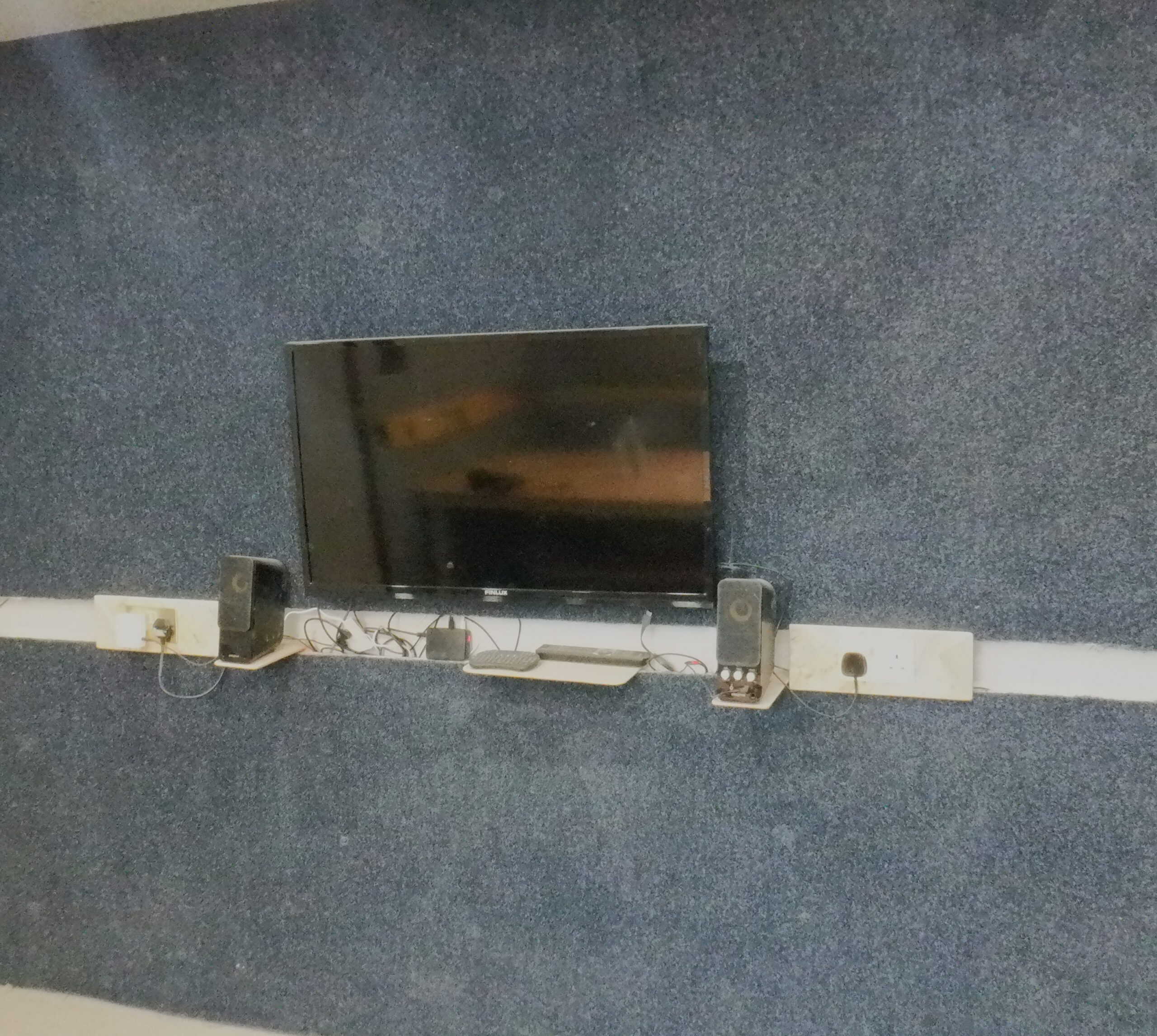
TV & Speakers
The last thing we did, was to find some old underlay, and some old carpet we inherited from the previous place we were living in. It only covered the first 1.9metres of our 5metres room and that will do for now. It makes that end of the room quite cosy and the sound quality is very pleasant indeed, very soft and warm!
Oh yes, nearly forgot about the little control screen and its buttons that sits just left of the door and about shoulder height. We 3D printed a black plastic surround, with four buttons vertically on the left and right side and a row of five buttons underneath, surrounding the touch sensitive 7inch screen in the middle. This will provide access to various information that is happening in that room, and beyond, but, it will have menus to allow you to configure how you want the temperature to be set at, how the lighting units should be set in various patterns, to suit your moods, and so on. It is the link to the rest of the house, including communication, security and other helpful services like shopping lists etc.
Door Wall Finished
That pretty much concludes the work on our Entertainment Room for the time being. We even put in a fan heater so it can be kept warm so we can go in and sit down at the table to do some needlework, or watch the TV!