This report covers all the work for building the Waste Air Ventilation main ducting, divertors and connecting of the first fan. We had started this particular job way back at the beginning of Summer but due to various issues including the temperature being too unbearable upstairs and being interrupted to do other tasks, it has taken this long to complete.
Preparation
Over the last few months, being interrupted by various things including very hot weather which made the upper floor almost unbearable, we have been preparing the materials so that we construct the Air Ducting upstairs. We ordered another pack of 25mm by 38mm battens which will be used to help anchor the sides of the air ducting.
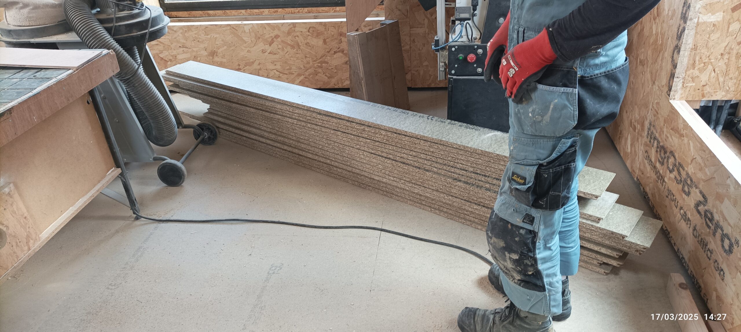
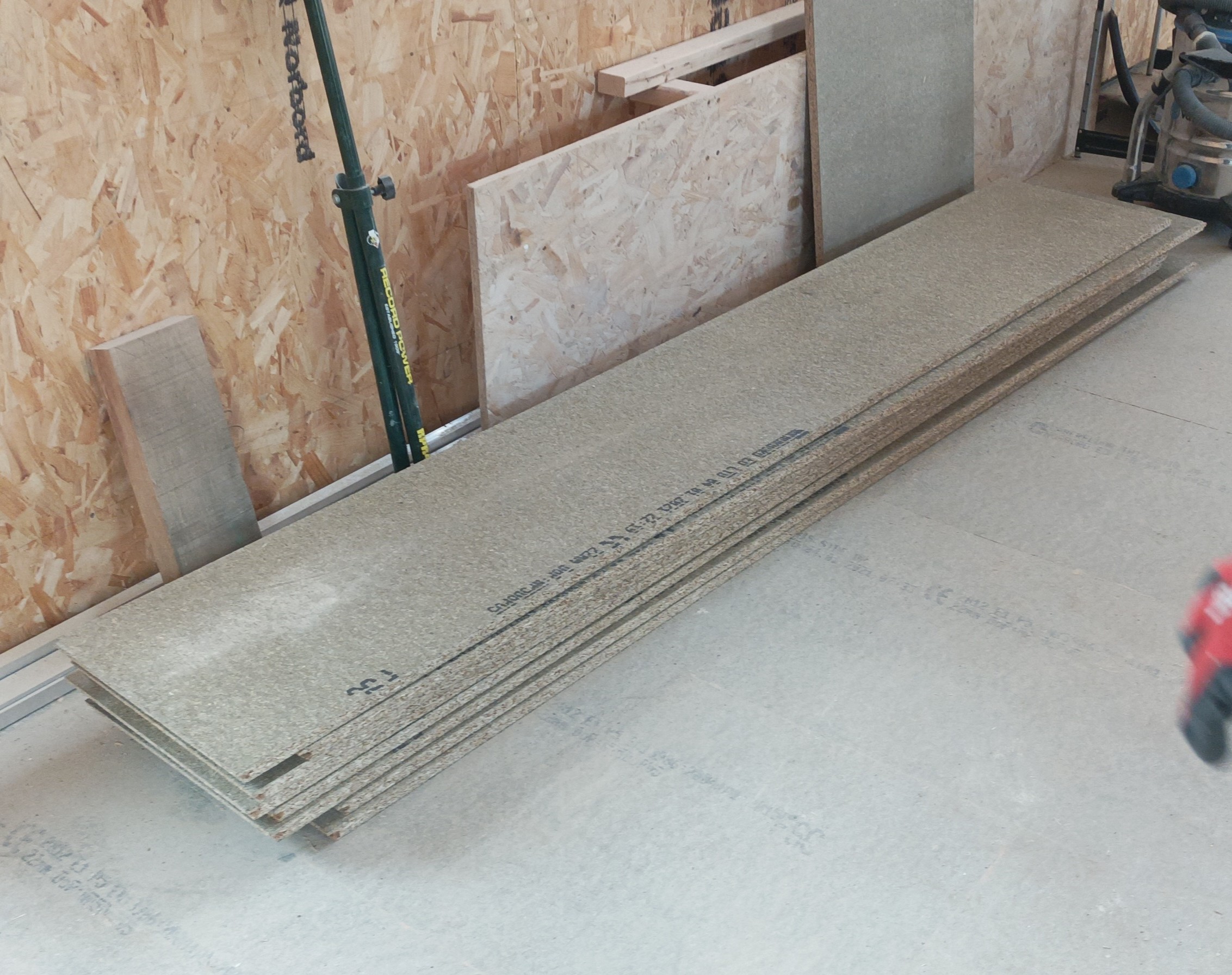
The material we are using, is all the left-over sheets of the chipboard floorboard pieces. We have 17 sheets of 18mm thick boards and 14 sheets of the 22mm boards. We are going to use the 18mm thick ones for the upstairs air ducts.
But first, we wanted to give all these sheets, both of the thicknesses, a couple of coats of acrylic varnish, to provide moisture resistance and a smoother surface inside the ducting. So, we laid out all the pieces of the 18mm boards right across our Great Room, pushing them together using their tongue and groove joints, and then sprayed the varnish all over.
We also ordered another tin, this time a 20litre giant pot of satin finish varnish for only £100.
Then, we repeated the same job and did the 22mm thick boards as well, using some of the new varnish.
The next job is to slice off the two long edges of tongues and grooves by running all of them through our table saw, with the fence set to trim off the tongue and grooves. We now have two piles measuring 580mm wide pieces of material, ready to be sliced up to make the pieces for the Air Duct.
Then, we sliced up the 18mm boards, into two pieces, measuring 270mm wide and the left-over piece measuring about 305mm wide. We decided that the maximum size of Air Duct we can make by using these chipboard pieces, will be 270mm tall by 250mm wide internal dimensions. We going to mount the Air Ducting tucked hard underneath the sloping roof so the design will be having a taller back vertical piece (the ones measuring 305mm high), which will have an 18mm wide slot cutting 10mm into the surface, near the top, so that it will support the lid, without needing a screw or bolt. This slot will be 270mm off the bottom edge, which of course, matches the height of the front vertical piece which also measures 270mm tall and the lid will go flat over that piece and get bolted down. We had 17sheets and therefore we had sliced 12 of them to create the first batch of pieces, and then we sliced the remaining five sheets exactly in half, measuring 287mm wide. We now have ten pieces which will go towards the pile of lids to cover the Air Ducts.
The next step is to cut that groove in nine of the wider 305mm pieces, so we set up the router machine into our modular bench and used a 12mm diameter square cutter. We set the fence so that we could cut this slot at exactly 270mm from one edge.
One problem we had with this task, was that our cutter bit broke. We were working it too hard and it was only on a quarter inch shaft. So we swopped over to half inch shaft but the only short cutter we had is 19mm wide (exactly three quarters of an inch), but that was ok because we have decided that the slot needs to be very slightly bigger than 18mm because of very slight wobbles in the creation of the slot, plus also the lids are not absolutely flat as well. We didn’t want to have to push hard or hammer the lids into the slot, and causing problems later on. We will put in a rubber draught excluder strips in the back of the slots so that the lids will form an air tight seals.
Construction
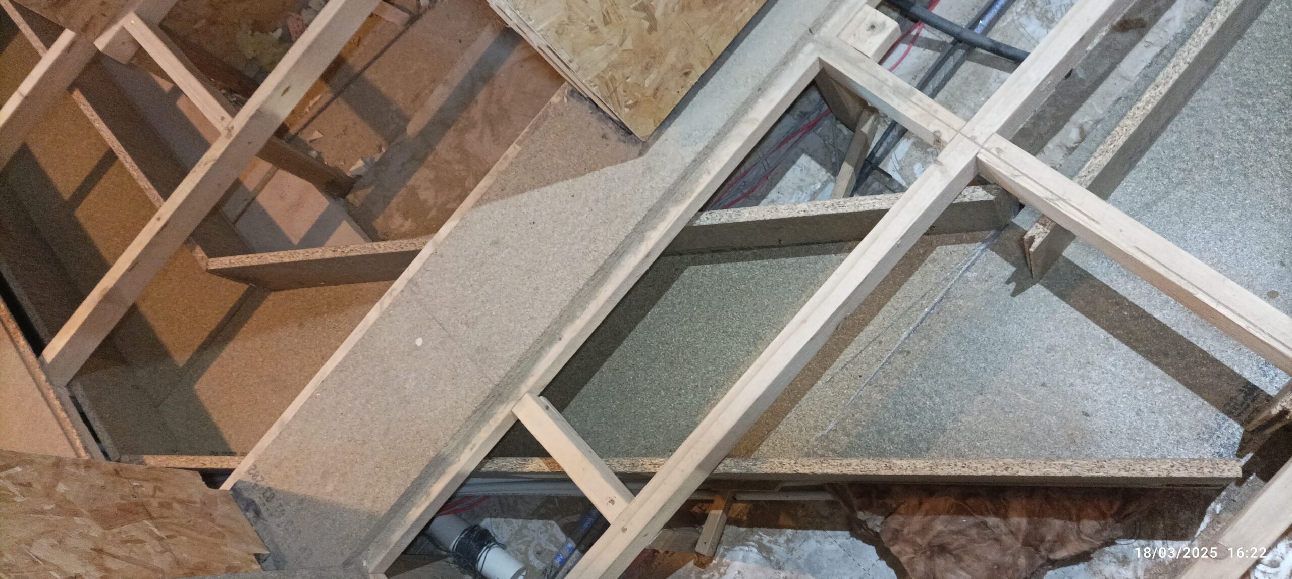
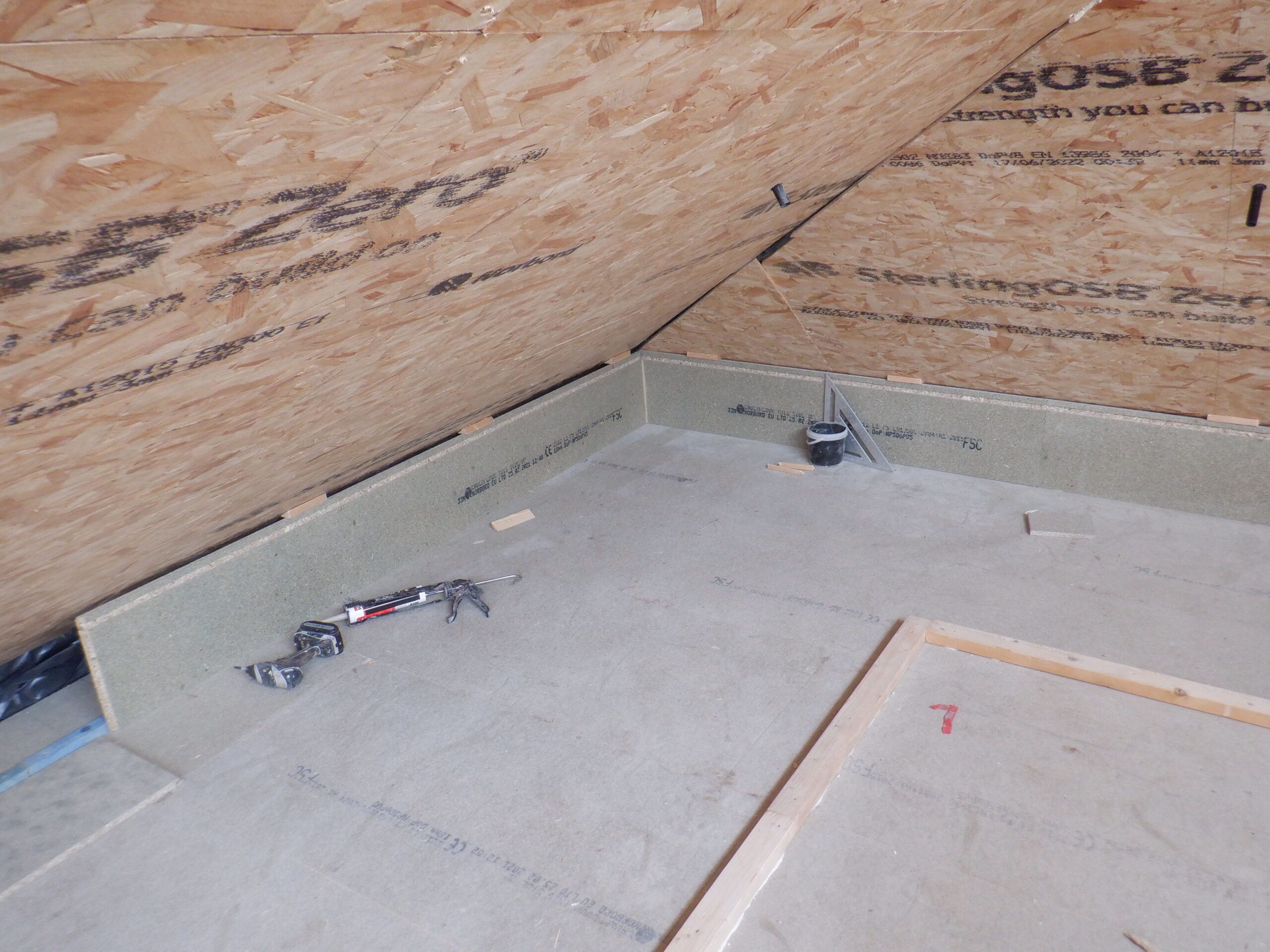
The next stage is to work out the minimum position for the back vertical piece (the one with the slot in) so that it sits as near as possible to the sloping roof, but maintain a dead straight line. We achieved this by using our trusty old green laser line generator, stretching all the way from the Gallery end, to the other end of the house, some 15metres away. We are doing the back triangular void spaces and it is one of the major Air Ducts, to carry the waste air away from the Skylight and the Great Room, plus also waste air from all the bedrooms downstairs, the bathroom, Tech Cupboard and all three ensuites too.
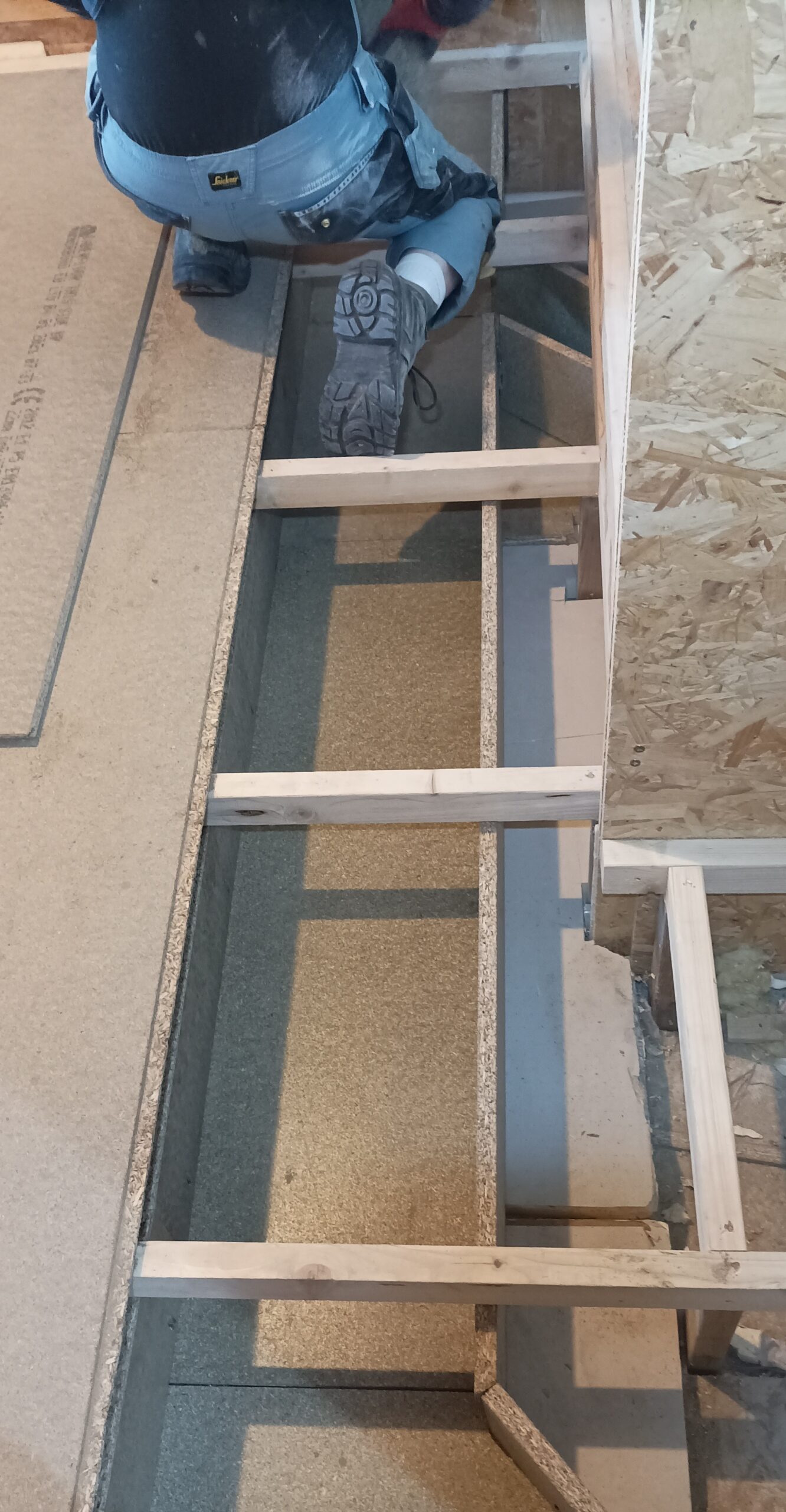
We had to move the laser line out away from the sloping roof a bit, to make sure that our vertical piece fits anywhere along a straight line. Then, we screwed down a line of 25mm by 38mm battens, which will serve a solid anchoring points to hold up the back vertical pieces. We turned the corner to go along the H section and finally a short section, another right angle corner, going towards the hole going down into the Utility Cupboard downstairs.
We then started laying out the prepared ducting pieces, specifically the back vertical wall, and realised that three lengths is too big to fit into the large open space behind the cold water header tank. These three vertical pieces are smaller and do not have a slot cut into them, because they will have more normal lids screwed down on both back and front edges. But, three lengths, each measuring 2.4metres long, adds up to 7.2metres, and it is too long. Both ends is intruding into the tight sloping roof and therefore we cannot use screws to clamp down the lid. This means that we had to remove 1 of these pieces, and situated the two remaining pieces so that they align with the access doorway for this storage area. It turned out rather fortunate because it ended up with a whole 2.4metres length piece just terminating nicely at the corner at the H roof.
So we trimmed off the unnecessary groove end and slid every board along so it is good and tight on all the tongue and groove joints.
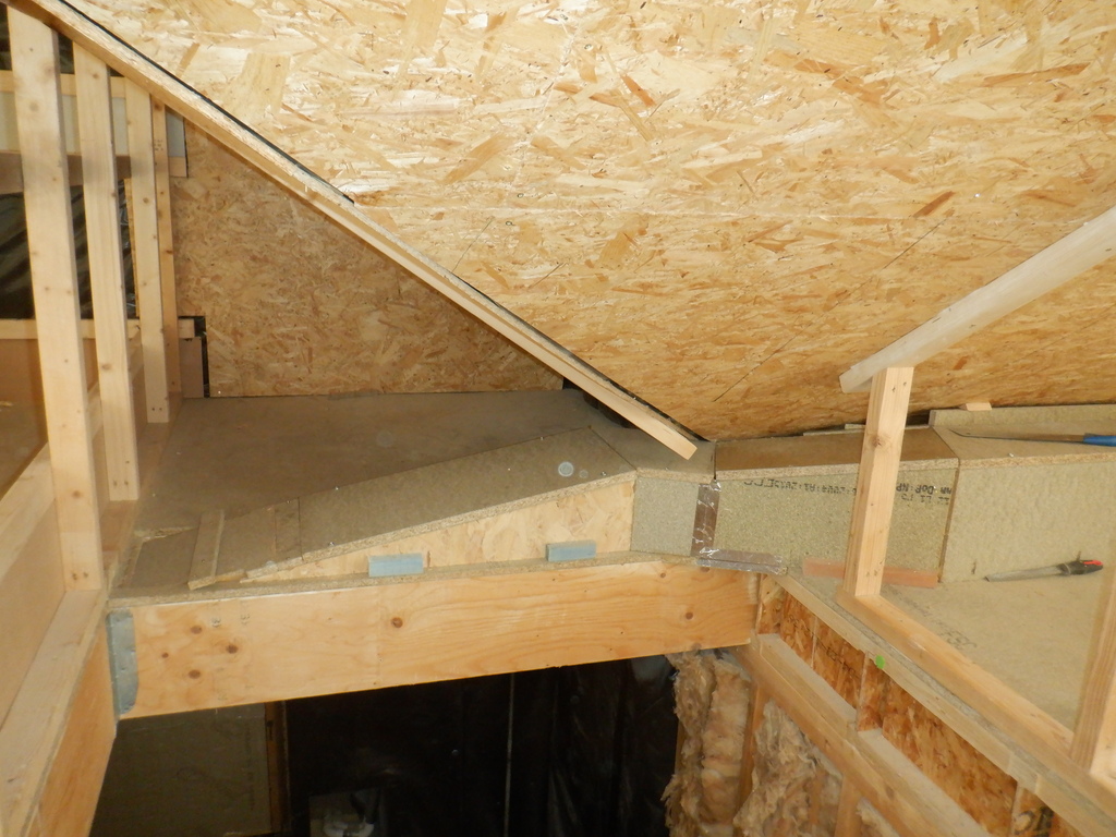
We then turned the corner and here we decided that we could use that third piece that got rejected from earlier, and position it into the dormer section so that we could put on a larger piece to serve both a lid for the air duct, but also provide a shelf connecting back to the back wall of the dormer. This left a piece of 1570mm long at the beginning and a second 500mm piece to finish off the H section, just after the dormer piece. The final E section, was easily accommodated with a single length, which will have to be trimmed down when we are ready to design and build a shaped and smooth divertor to get the waste air down into the Utility Cupboard.
One of the task to do, was to glue in little wedges between the sloping ceiling and the top of these back boards so that the whole ducting is good and solid. We had loads of cut-off pieces from another job a couple of years ago, an angled piece and it was very handy chopped up into 4inch pieces.

Starting the Extract ducting
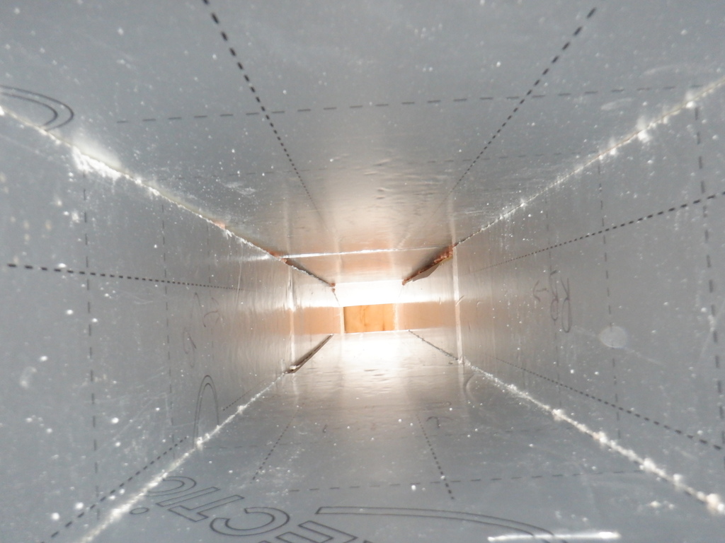
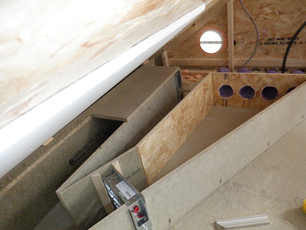
Now, we proceeded to mount the front pieces of the air ducting, which all has now eight little pocket holes drilled out along the bottom edge on each board. We put on the lid and drilled bolt holes, two of them, in each lid. The front pieces had their original tongue and grooves so we could just slot them together to form a continuous line and once we had put on all the lids and their bolts, we could drive screws into the pocket holes and anchor the front board into place. When we got to a right angle turn, we stopped 700mm from the end, to allow for a decent sweep bend to help guide the air around these sharp right angle bends. We continued along the next section, the H, and again stopped 700mm short and finally, put the last front piece, but not fixed down, ready for the transition for the air to be bent downwards into the Utility Room.
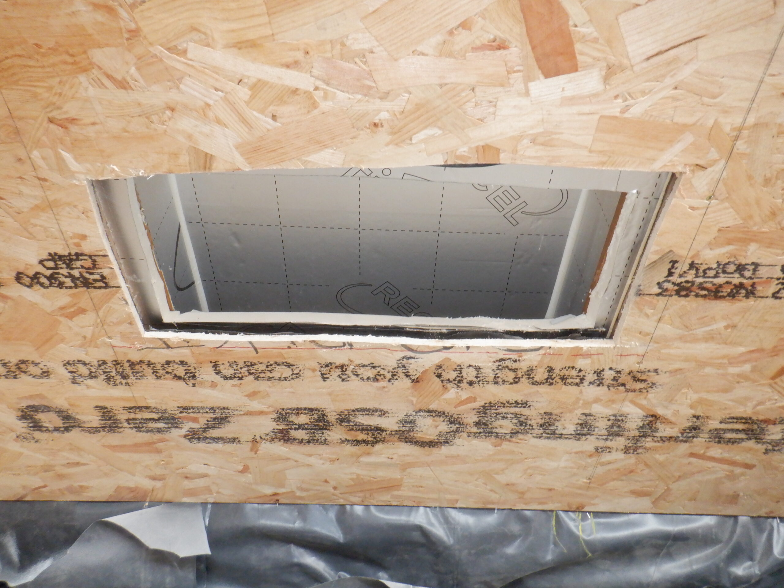
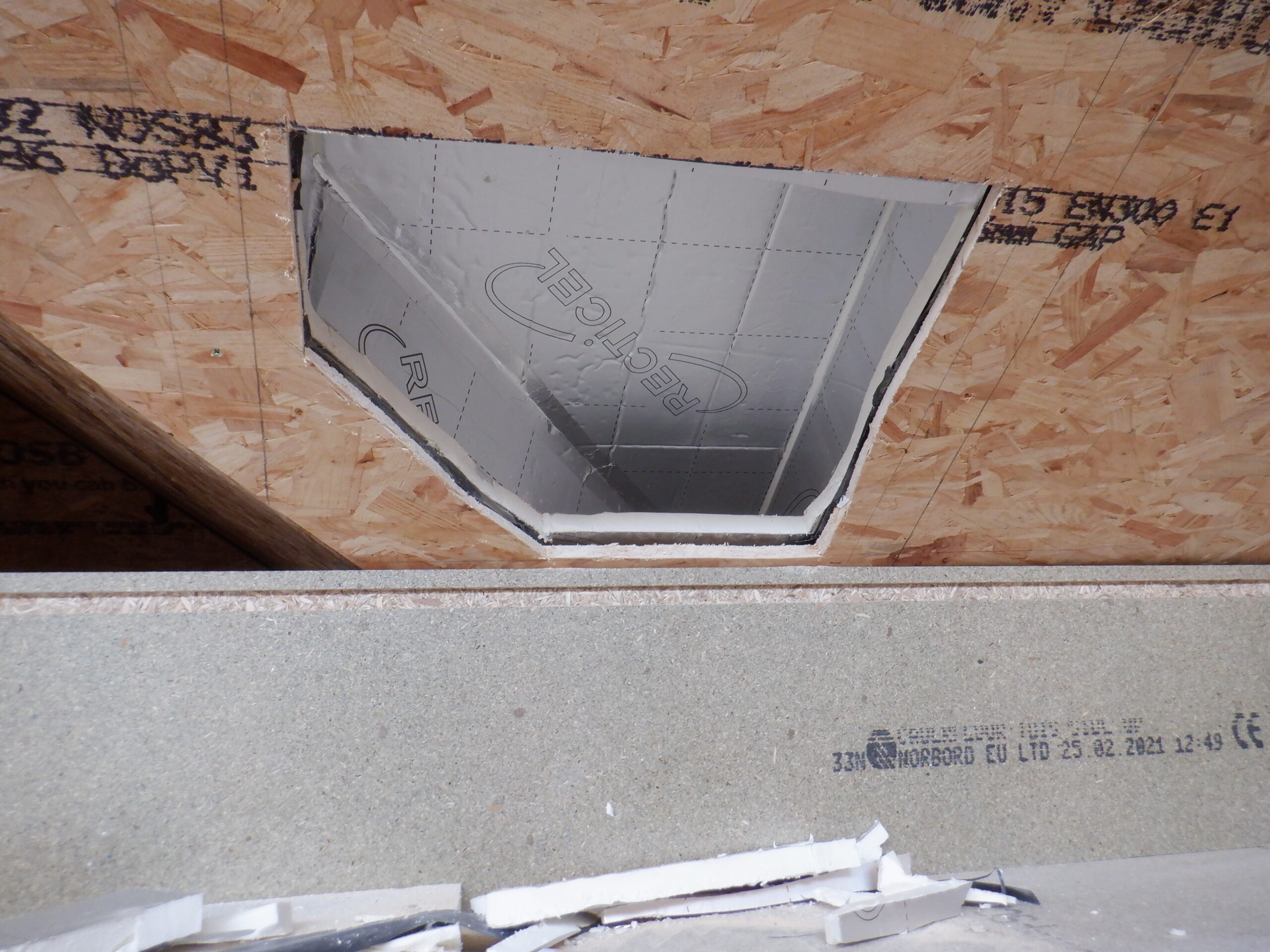
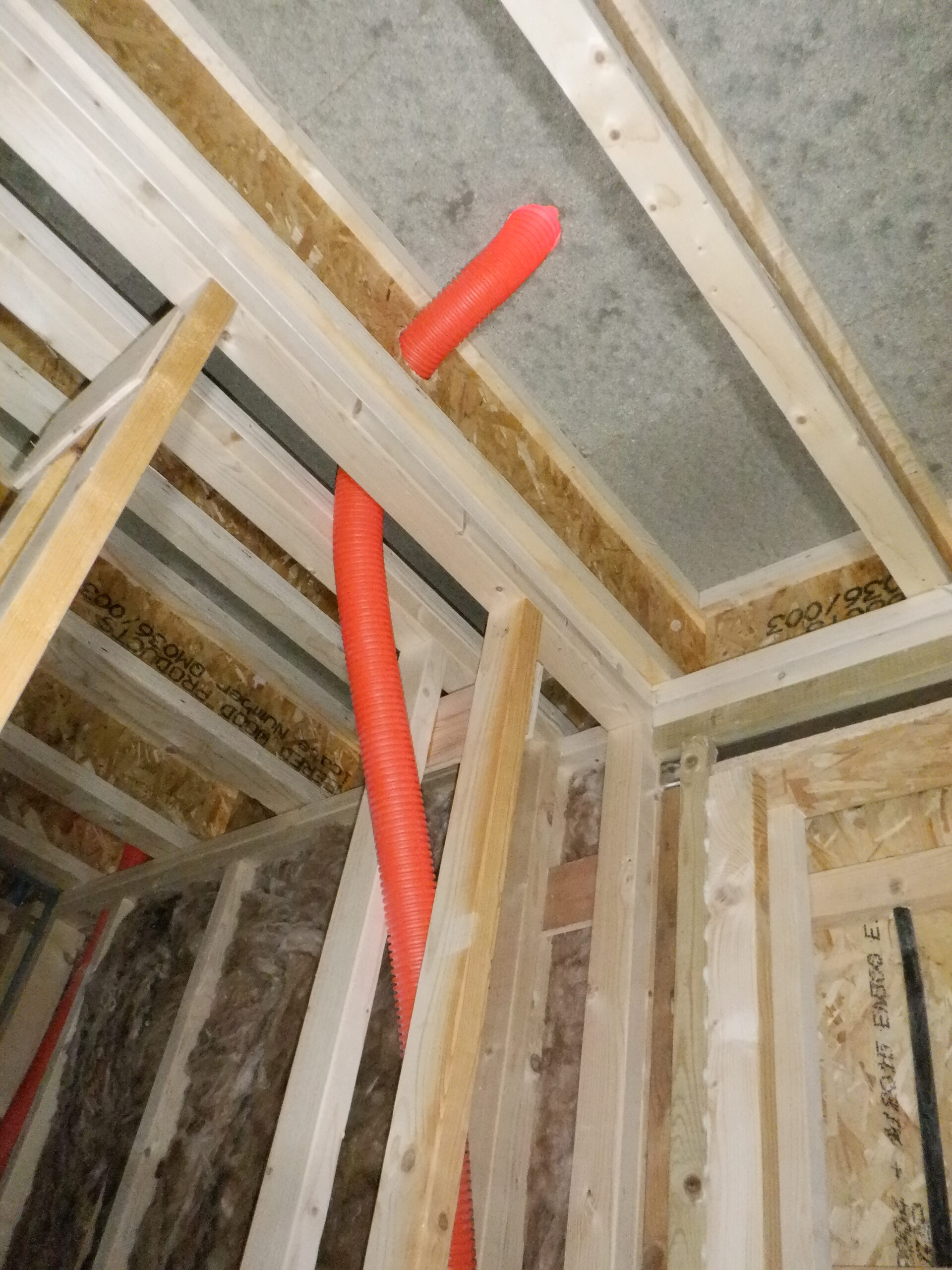
The next task was to cut upwards into the roof rafters, at very specific locations, to open up access to the air duct we had previously built many months ago, that runs inside the roof rafter space. There are two of these “chimneys” that will draw the waste air from up in the Skylight and it is a rather major element of our ventilation system. So, we needed to gain access to these chimneys. We carefully sliced our way through the 11mm OSB layer, and then sliced into the 25mm thick PU foam boards as well.

Exit of left duct from skylight
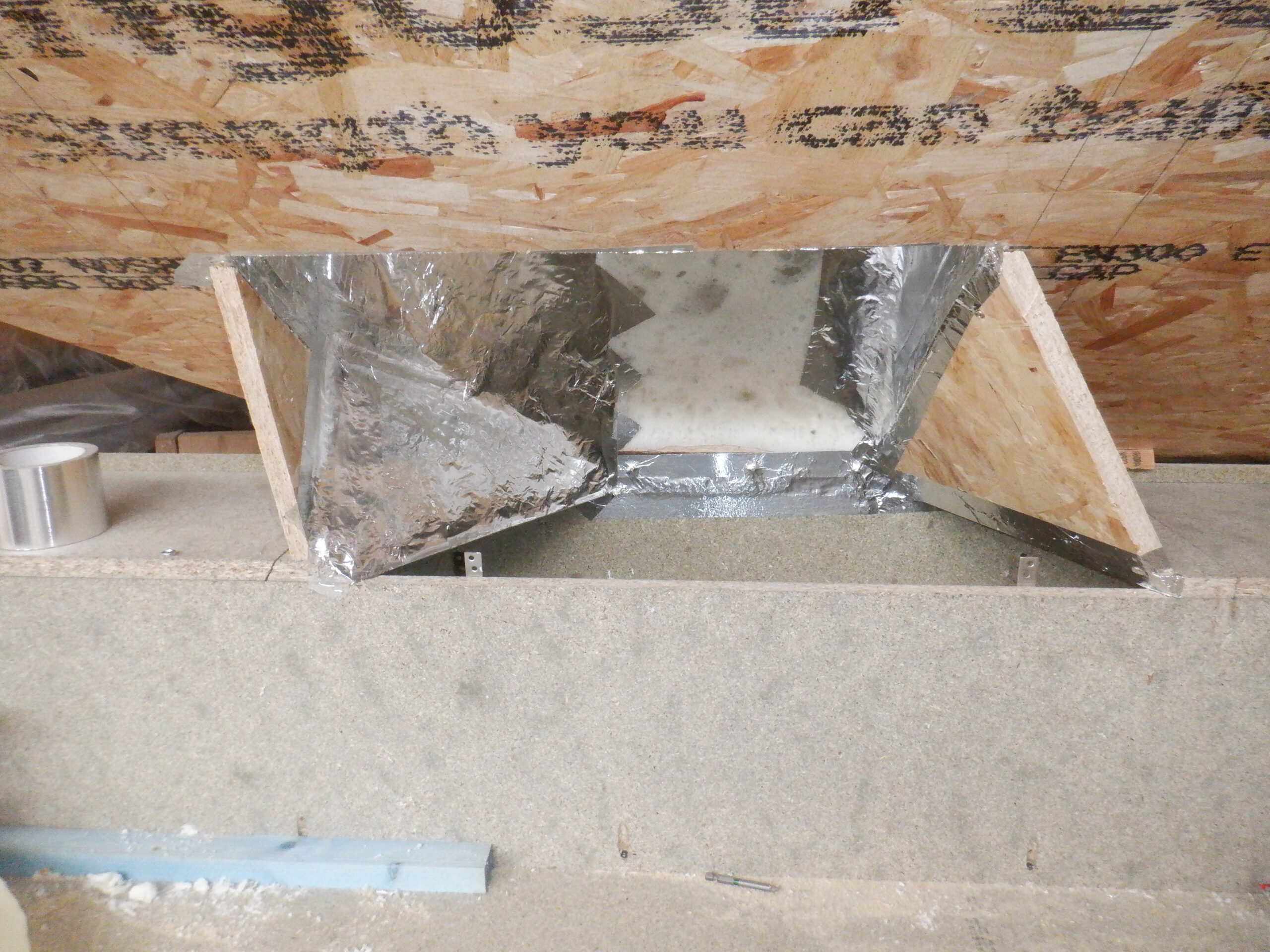
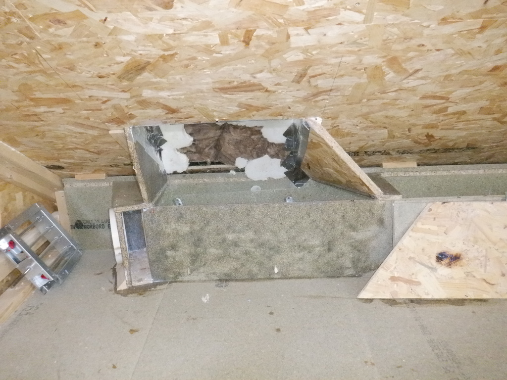
The second chimney, located at the north end of the Skylight, has the valley ridge beam intersecting at the bottom of the chimney which added to the complexity but we we fitted a small piece of flexible thin plastic sheet material and curved it from the sloping chimney, on the right side, and terminated it on the wooden back board of the air ducting. Next, on the right side again, we put an angled piece of board to join from the sloping edge of the chimney’s hole and the lid of the air ducting. We then put another triangular piece of chipboard “lid” on the left side and then fitted a vertical piece to join to the left side of the chimney’s hole. Now we proceeded to spray PU foam into the corners, mostly concentrating on the left side, to build up a solid layer which we then scraped it to form a gentle curving surfaces to guide the air around that is gusting down the chimney. We covered up everything with aluminium tape to seal it up and give it a nice smooth surface. The final piece to make is a removable front cover which we used a piece of 12mm ply.

Exit of right duct from skylight

Connecting waste air from skylight to duct (I Wall)
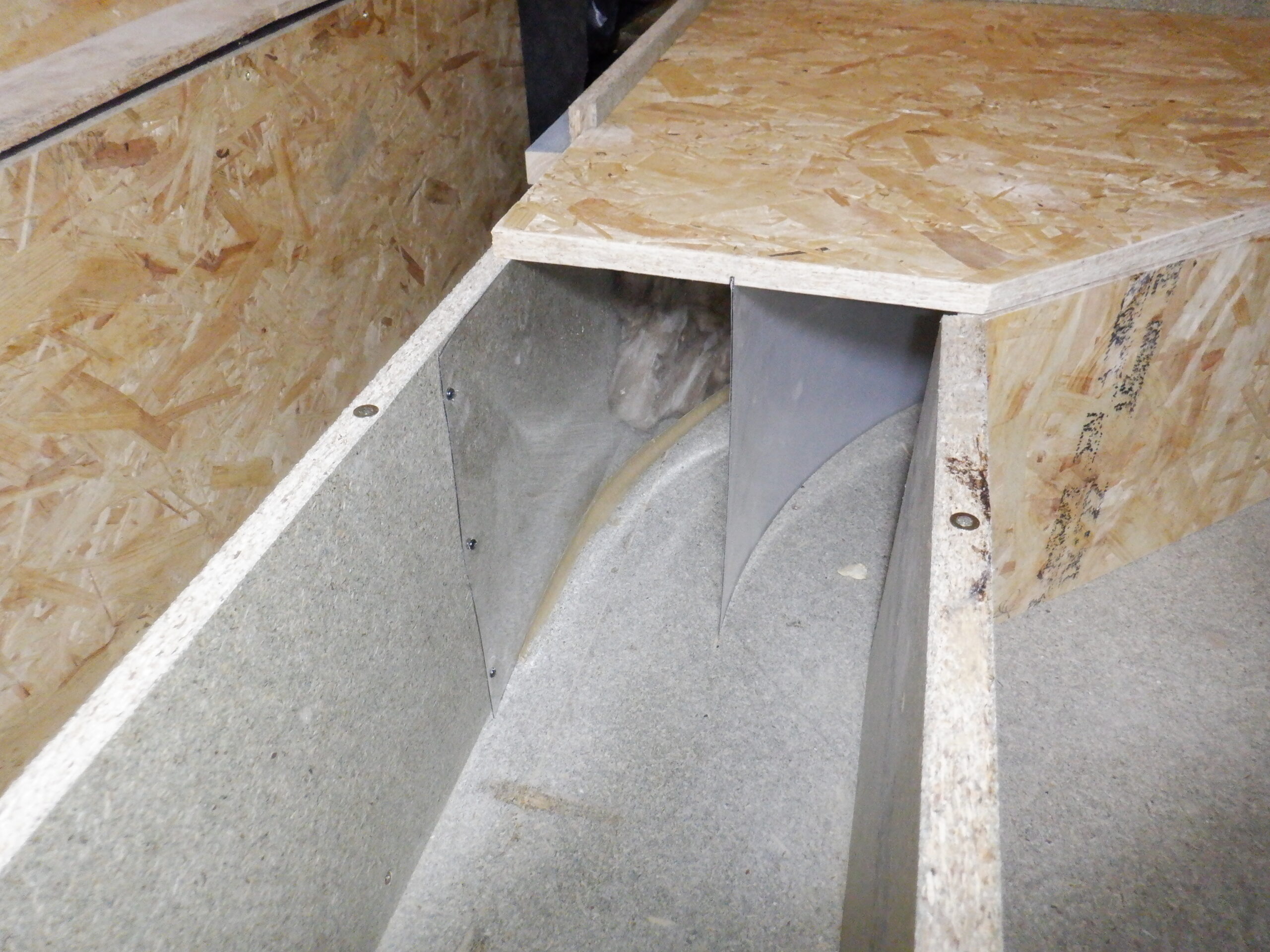
Moving along the ducting, to the first corner, what we call the H-I corner and then created a sweep bend by inserting three more pieces of the thin plastic sheet material. We cut a tiny little groove into the floor by using a router with a tiny 3mm cutter bit. The router was then affixed to a long piece of ply where we could screw through at various radius positions into the floor, which then guided the router to move in a perfect curve. We did this for our second middle strip of plastic because it was in the middle of the air stream and it needed minimal fittings to keep the air flowing smoothly. We did a mirror of this slot in a piece of OSB board that forms the lid. It measures more than 700mm square. We pulled the second strip of plastic into the slot and then applied a little bit of construction glue to fix it into place. The first and third strip of plastic were fixed to the back of the ducting and around the inside of the front board respectively. These were fixed into place using short little dome head screws and a strip of aluminium tape covering up the edges. Finally, we inserted a diagonal piece of vertical board to close off and protect the plastic.

Air duct corner with vanes
We then repeated the whole process again for the second corner, in the H-E corner.
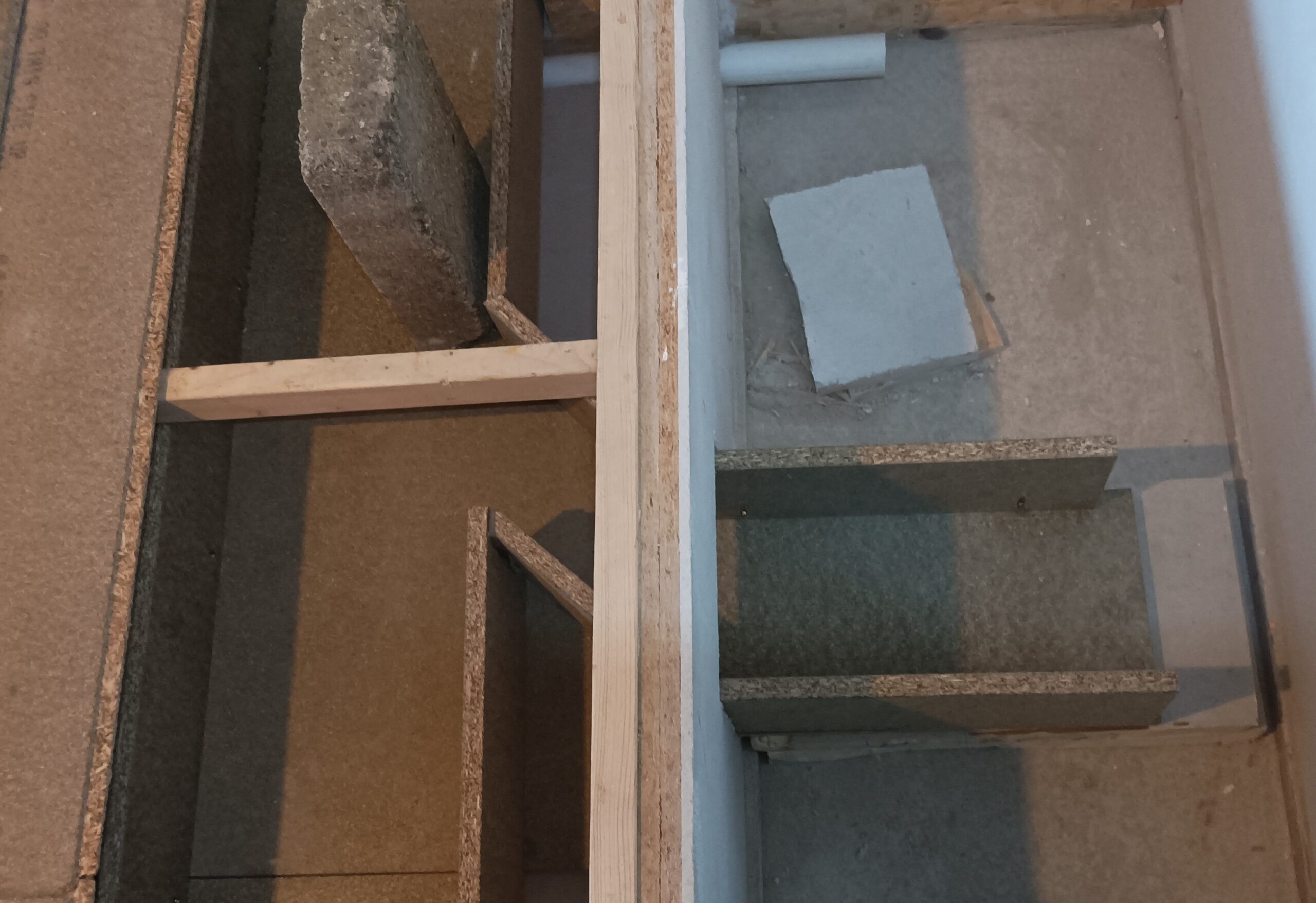
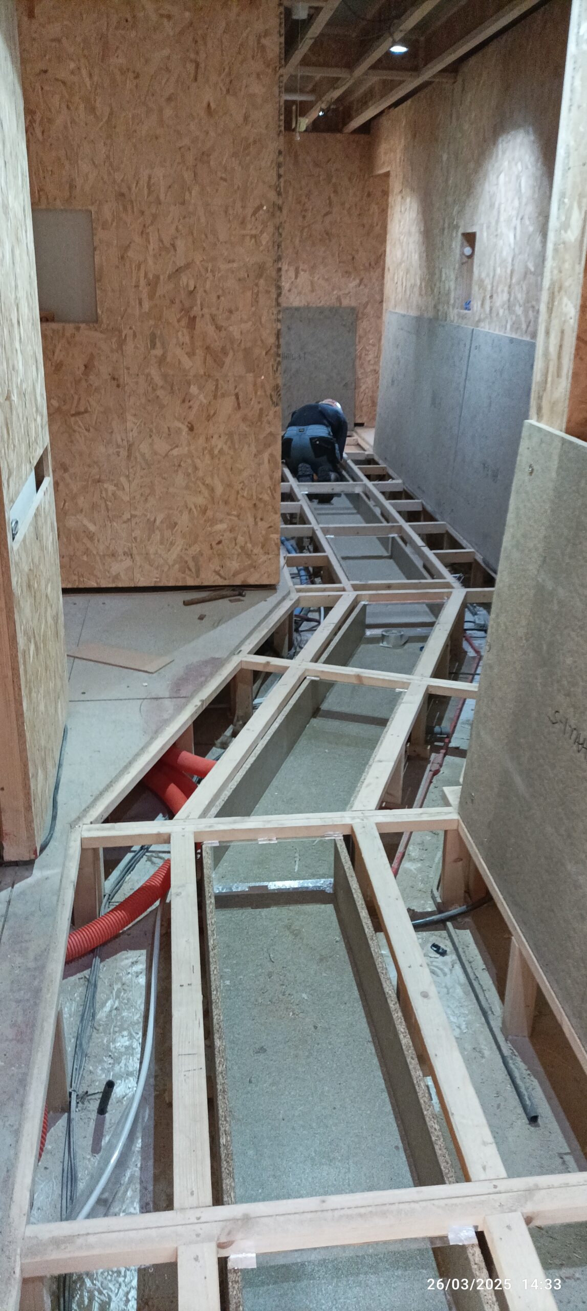
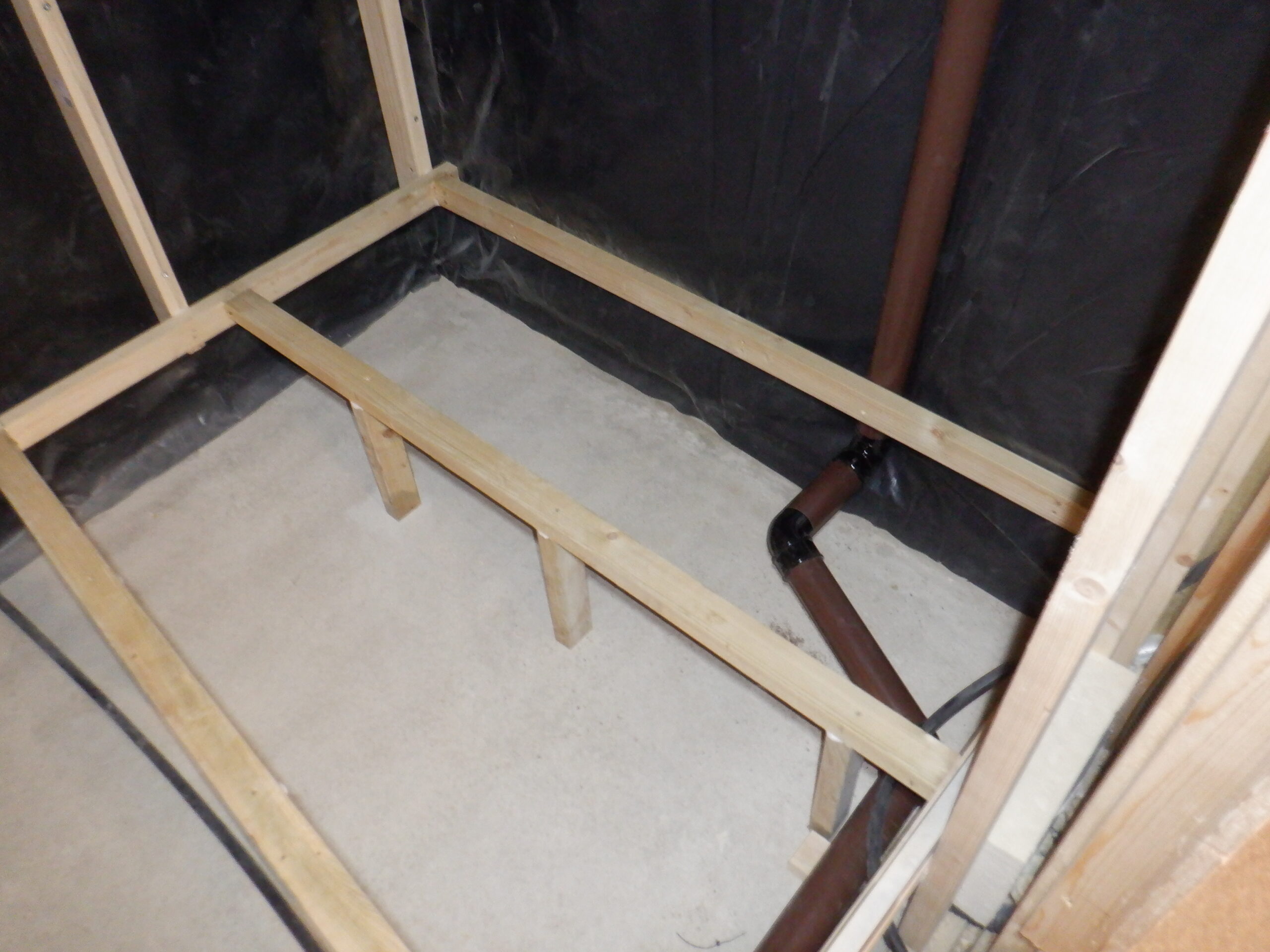
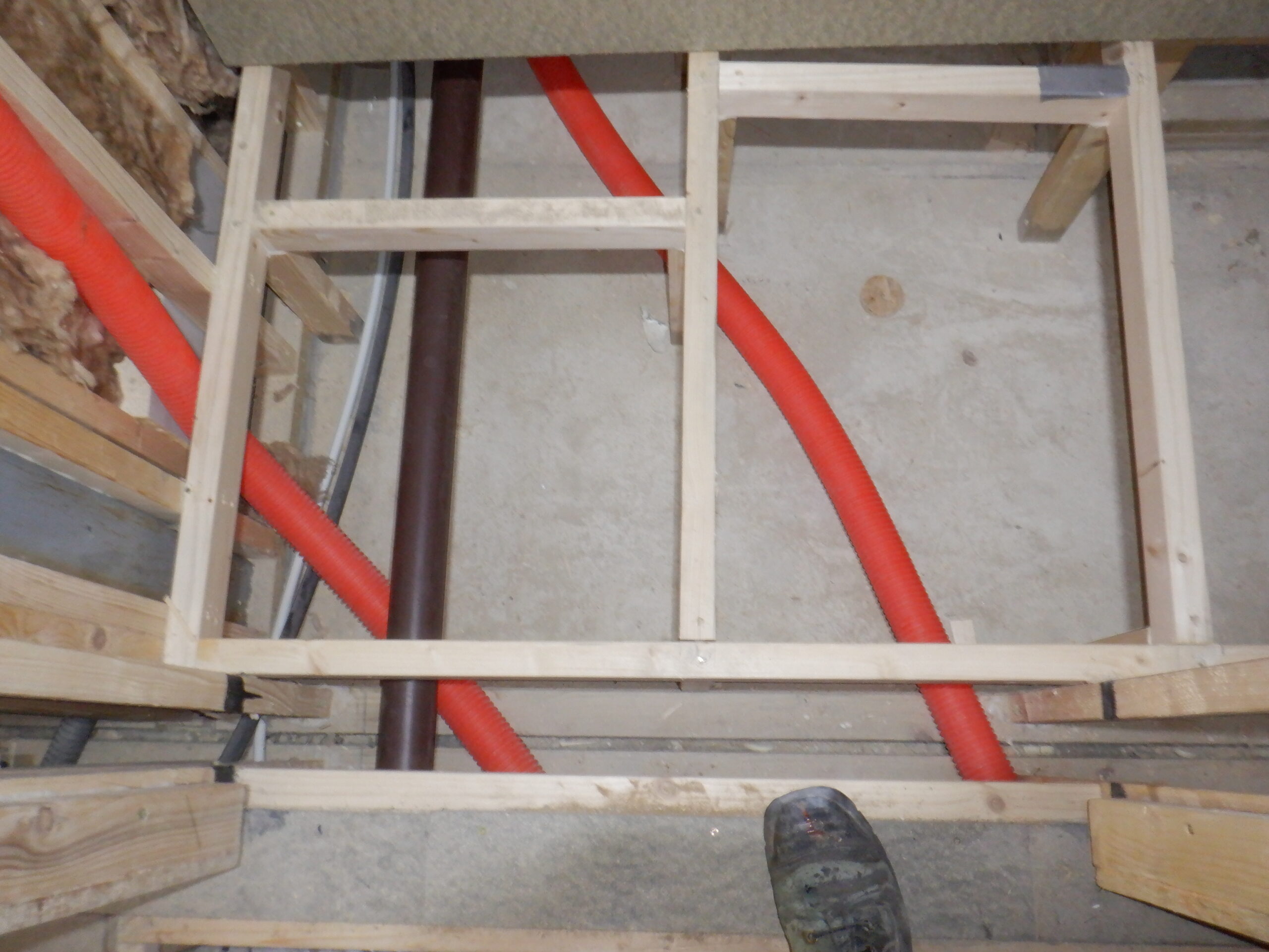
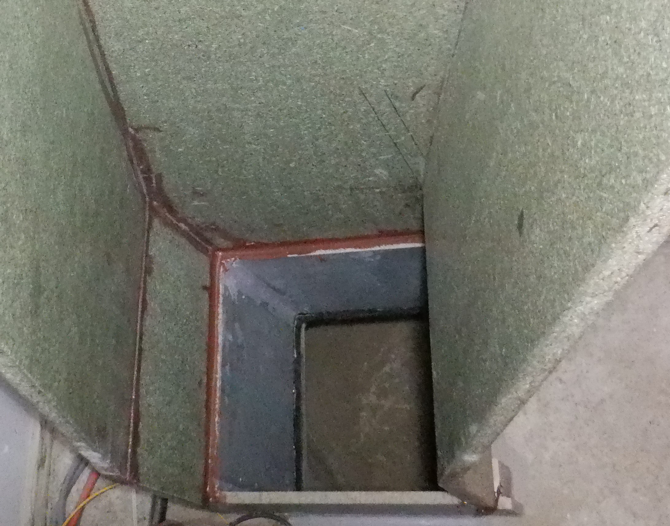
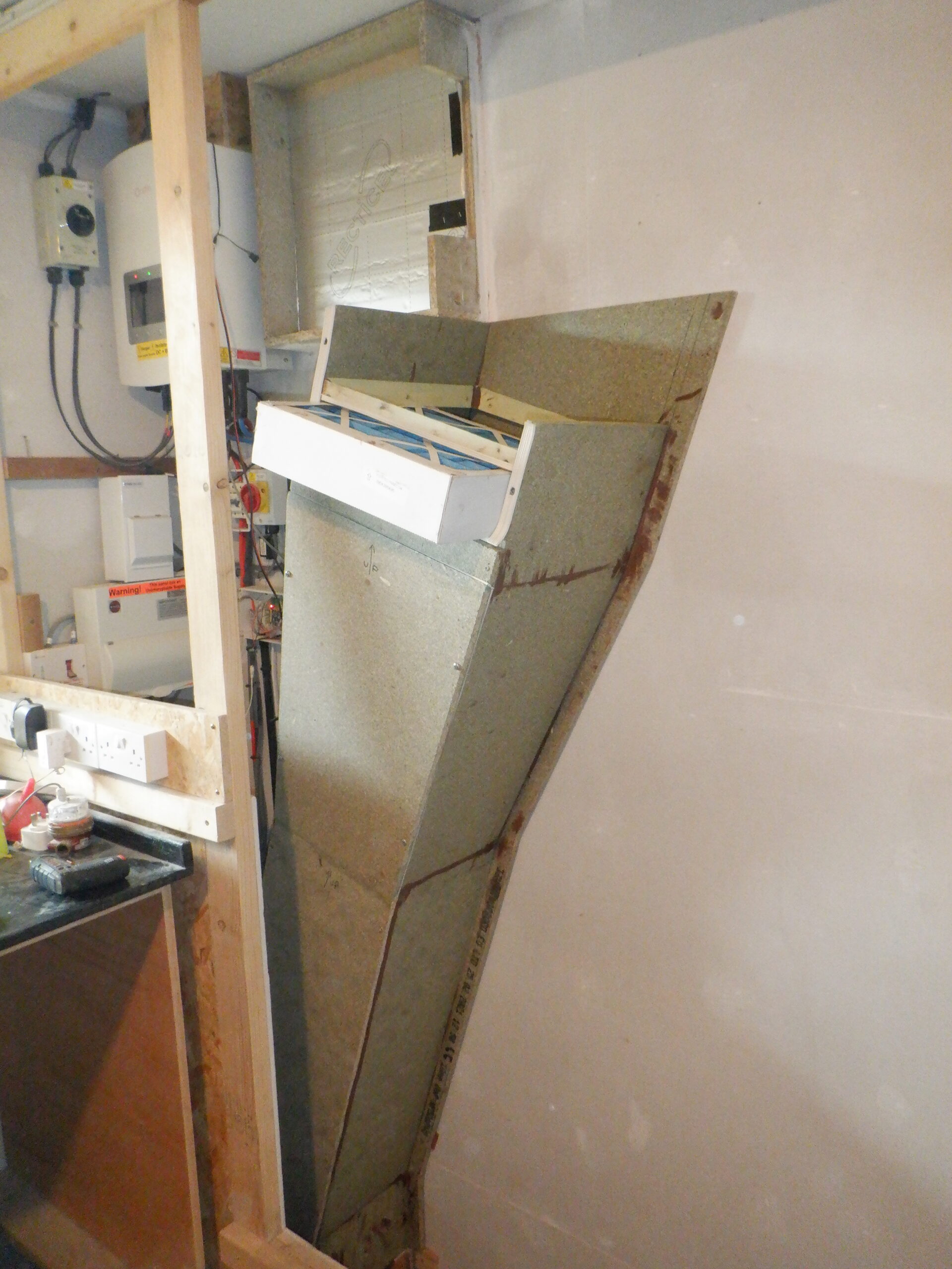
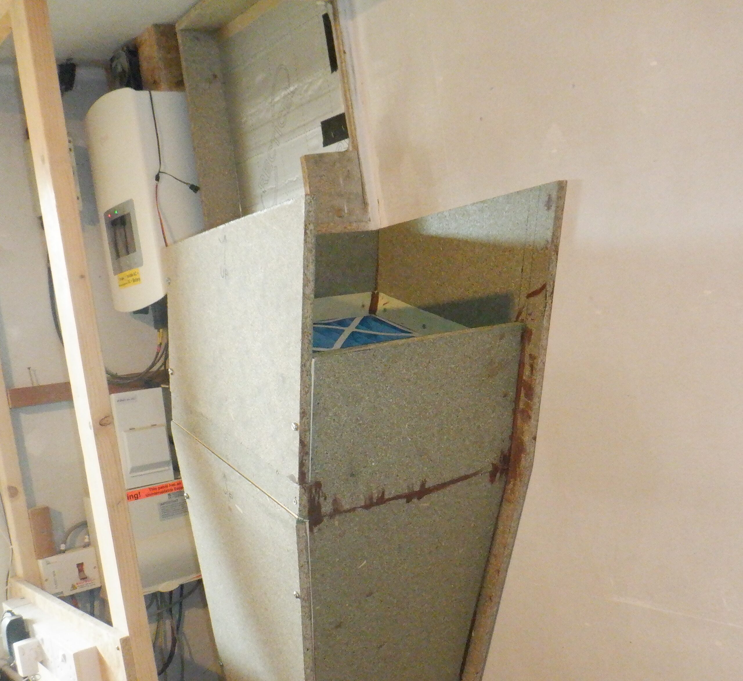
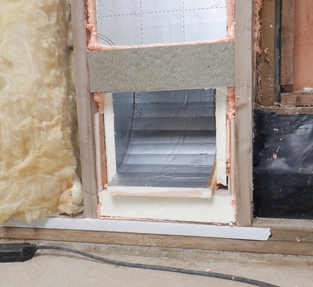
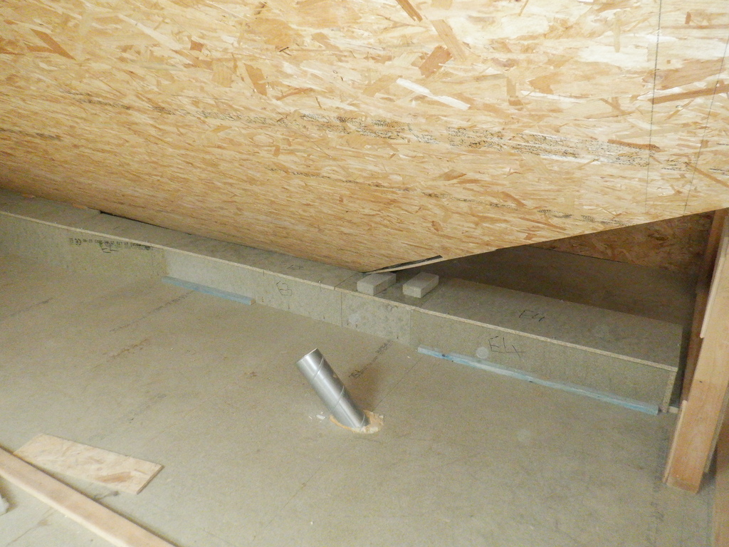
The next situation to deal with, is the point where the air needs to join together with the other main air ducting coming along the front of the house, and then being swept down into the Utility Cupboard downstairs in the Utility Room. The hole in the floor is tucked right underneath the sloping ceiling as it needed to enter into the cupboard downstairs as close to the back wall of the cupboard as possible. This means that the main ducting has to be slightly bent backwards and also reduced in height as well. We carefully slice up some of our chipboard material to form a back vertical piece measuring 190mm high and we glued and fixed this piece to a batten screwed into the floor just behind the hole. Then, we cut an angled sloping piece for the left side that goes from the back of the hole and grows taller slowly until it reaches the end of the normal ducting back board (the one that has the slot in it). It is quite a way away so it is a gentle change of direction.
Now tackling the other side, the right hand side, we decided to keep the ducting height at the same height because all we needed to do was to join up to the channel that has been running under the floorboard (inside the first floor joist space), bridging across the Study. The channel comes up through a hole measuring 350mm wide so we knew that it was ok to keep the internal height to the 190mm we already used earlier because the total cross sectional area is comparable to the rest of the air ducts. So we cut and screwed into place several pieces to form a box and a lid for the hole and connected back up to the Utility hole.
Waste Air from Kitchen and Great room 1
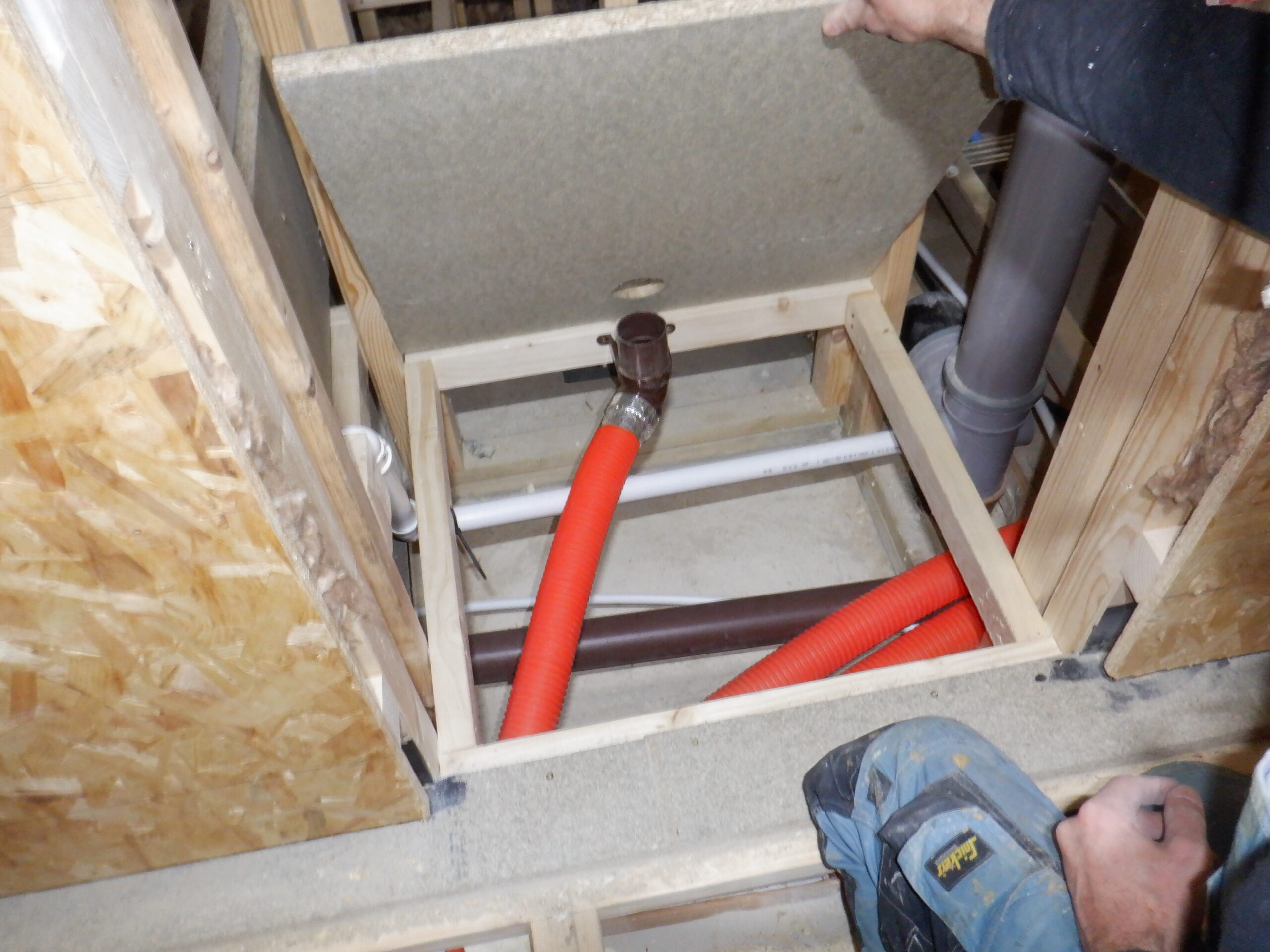
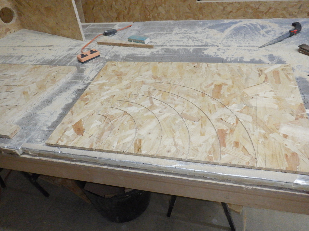
At this point, we needed an air diverter module, to help join the two stream of air and sweep both of them downwards. We got two pieces of 6mm MDF sheets and cut a series of shallow curving slots, using our router on the rotating arm like before. The hole in the floor that we wanted to bend the air around, measures 230mm wide by 570mm long and we decided that two thirds of the left side of the hole will serve the air ducting coming from the left (this has the majority of all the building’s waste air coming from the Skylight, Great Room, and all the rooms at the back half of the house) and the other third will serve the right hand ducting (air coming from the Conservatory, a bit of Great Room, Kitchen and Entertainment rooms). So we needed two curving strips of plastic for the left side, and one piece for the right side. We drew out the curves on the MDF to make sure that we got the layout correct and then cut the three slots. We mirrored the slots in a second piece. So using construction glue, and lots of fingers, wiggles and cursing managed to get all three plastic pieces into their slots and placed four bricks on top to hold everything together while the glue cures.
We then trimmed the excess MDF material away so we ended up with a neat module that would slide up from below. Well, that was the plan. We discovered that we very slightly made the width a couple of millimetres too wide. When we pushed the module up, it started buckling the thin plastic curved bends. So, we had to get our power planer to remove a thin layer of the chipboard material that has lined the hole. After making that awkward adjustment, we finally got the divertor module up into place and locked down with screws.

Air duct connecting upstair to utilty (1)

Air duct connecting upstair to utilty (2)
Now, we can put the various lids on top, some of them were permanently glued and screwed down, while the remainders were bolted so we could lift a lid section for maintenance etc.
We now have that section done! We are getting there!
The next bit to do, is the ducting running along the front of the building, as mentioned already, coming from the Conservatory etc. At this point, we have run out of 18mm thick chipboard planks, especially the back with the slot pieces, and also lids. Therefore, we had to cut up several boards from our 22mm pile. This meant that the slot needed to enlarge to 22mm wide, which means that the height of the front piece had to reduce to 260mm (losing 10mm, which is not too critical). So we made two back boards (measuring 2400mm long) and we did our trick like before, using our green laser line generator to find the best line to follow underneath the sloping ceiling. We put down a length of batten and then screwed these pieces into place. The only complication, well, a major one, is the left end where we needed to duck under the slope of the corner of the ceiling, cut across the corner of the stairs and join up with that bridging channel going under the Study. It is definitely much more of a bend and we needed to control the air flow more neatly, with proper sloping lids etc.
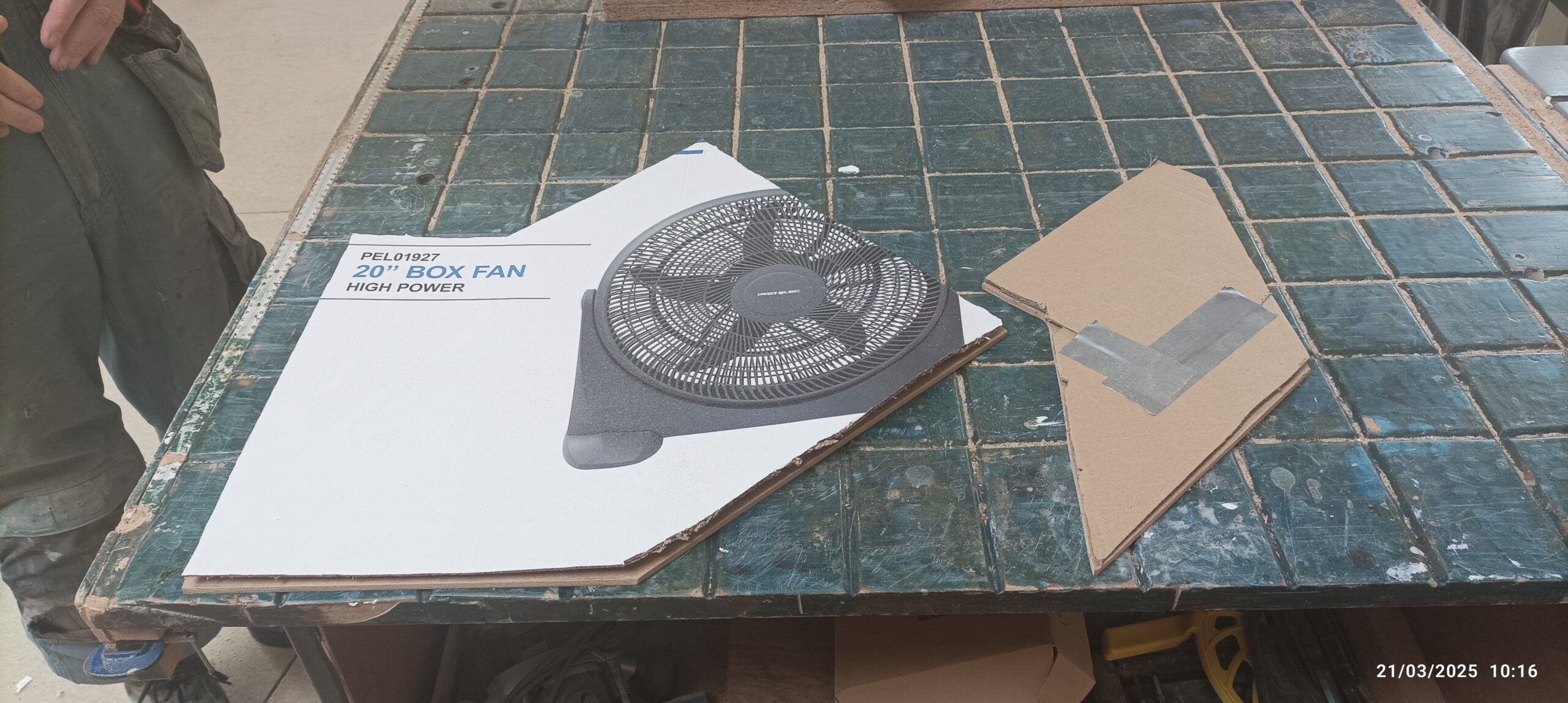
At this moment, we realised that we needed some more ducting mechanical devices, mainly, flow control valves so we decided to order a whole heap of bits and pieces. We ordered twelve round 150mm air vents, two 200mm air vents (for left and right side of the Great Room) and a single large 250mm air vent (that goes right at the top of the Great Room, right up in the Skylight). Plus also a couple of 100mm and 80mm air vents too. Next, we added a piece of aluminium flexible corrugated “stretchable” pipe measuring 200mm wide and finally, we put in two 50mm thick by 300mm square dust filters. That took a week to come.
So, we carried on getting that complicated ducting built. It took a lot of measuring, fiddling, trimming etc. before we managed to get a completed duct.
Waste Air from Kitchen and Great room 2
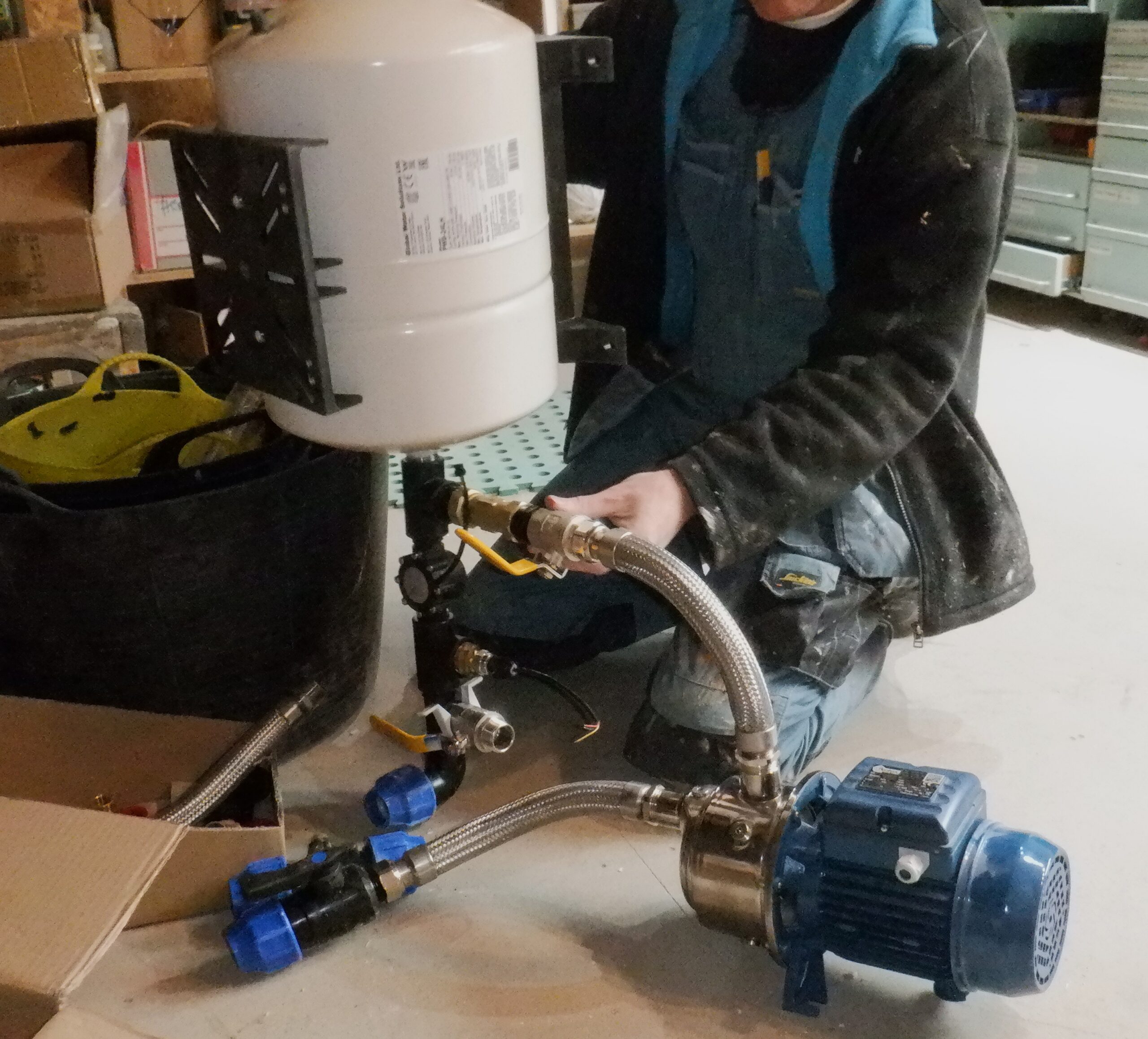
Another section that we also started working on while we waited for that order to come, is building the divertor and filter that goes in the Utility Cupboard downstairs, to join to that hole (now in the ceiling ) that joins to the air ducting from upstairs. We needed to get the filter (the one we are ordering) to be removable because the cupboard is only 500mm deep and the filter is 300mm square and we would need another 300mm of clearance. Then, the fan motor itself needed to be positioned, before the output of that goes into the heat exchanger. We bought some 25mm right angle “l” shape plastic so that we could make a cage like section to hold the filter and allow it to slide in and out. We also created two large circular collars to make an adapters for connecting to the fan.
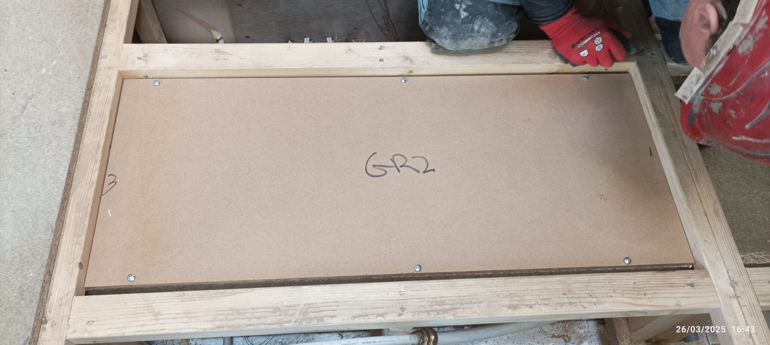
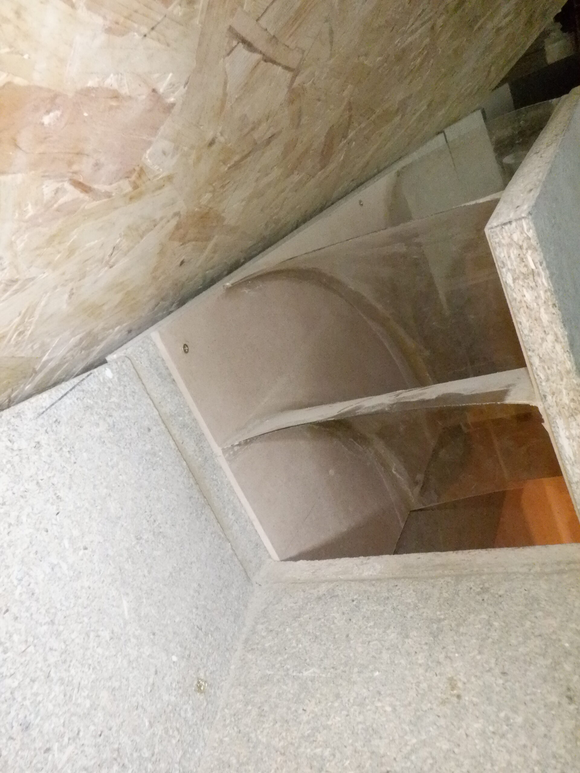
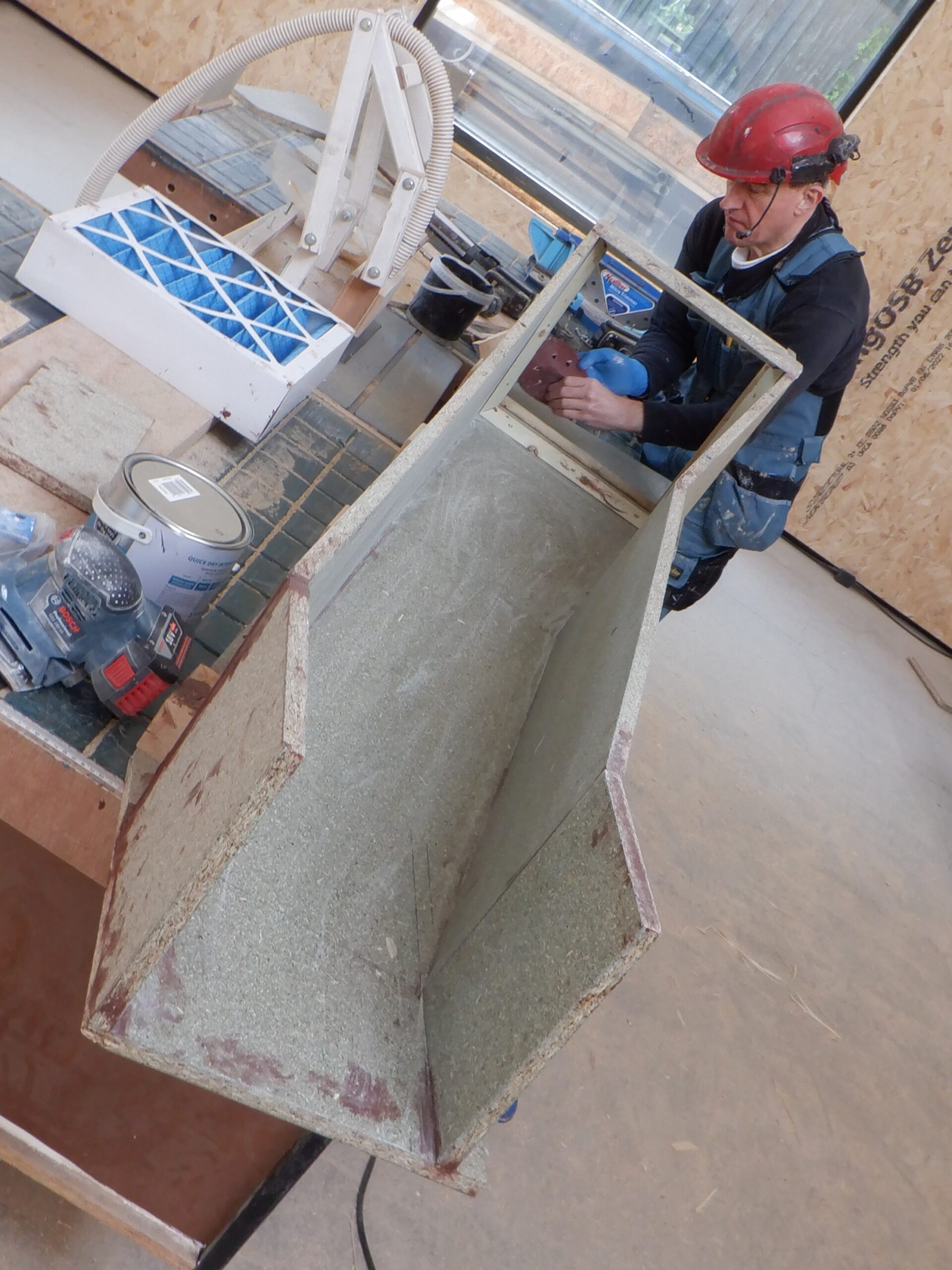
Then we progress to creating the large box that will sit underneath the chimney and inside this box will have sweeping curves of plastic to help guide the air around the corner as it is being sucked downwards through the hole in the ceiling. We put in six curves, ranging from a tight 100mm radius curve near the filter, gradually stretching out the curves until the outer bend is measuring 400mm radius. We marked out the centre points for each quarter circle on both the back of the back and the front (the “lid”) and used our little router on a rotating arm to cut all the slots.
Redirect and Filter box side with slots for vanes
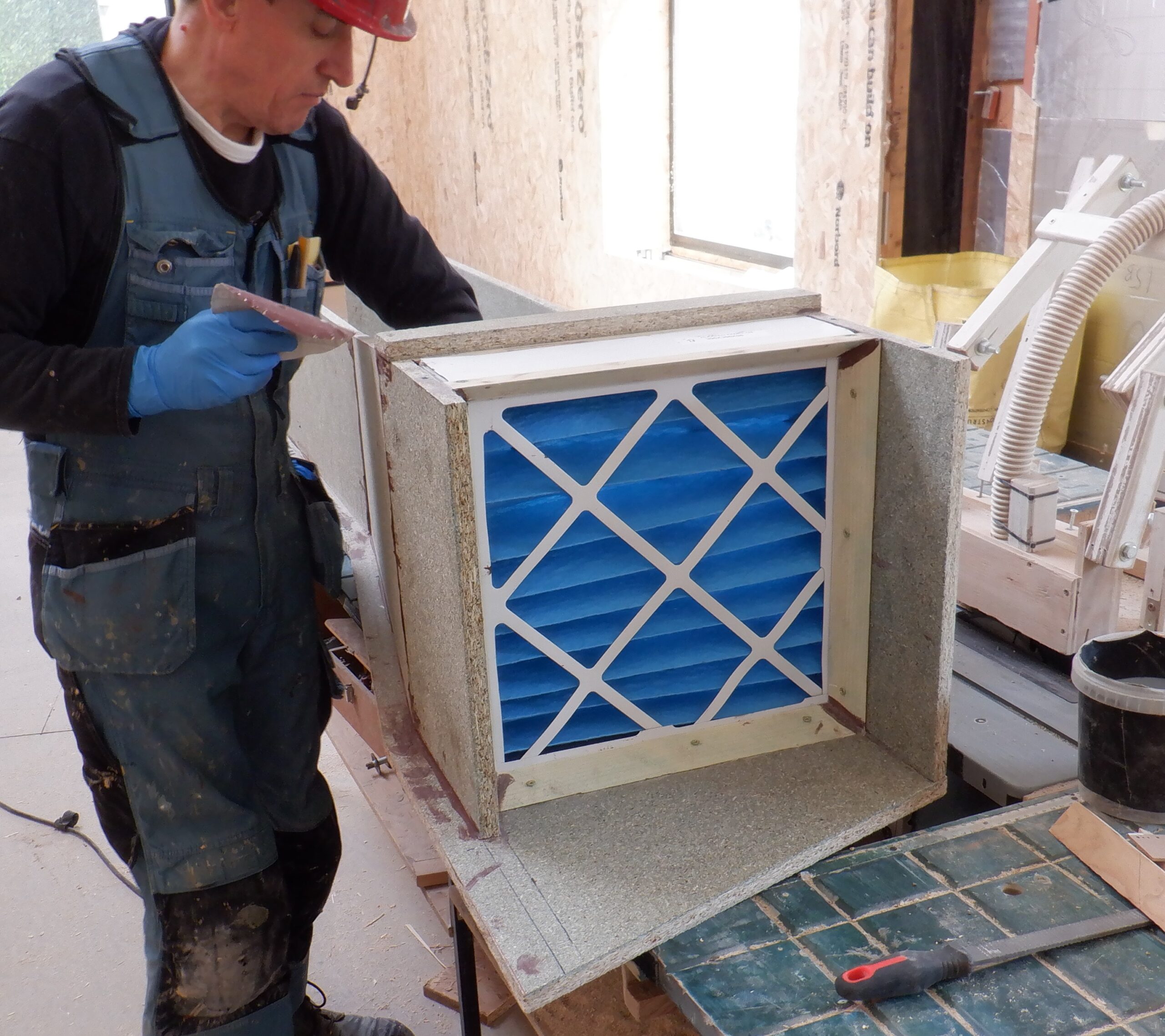
We measured the height inside the box which was 361mm to 362mm and the slots we just cut were 5mm deep so we proceeded to slice our sheet of thin plastic, cutting a strip of 370mm wide. The width of the sheet is 1250mm and we realised that we could generate three of the curves out of one strip, namely the 400mm curve, the 340mm curve and the smallest one and there is no left-over. So with the second strip, we cut the final three pieces, the 280mm curve, the 220mm and the 160mm radius and we had about a 200mm left-over piece.
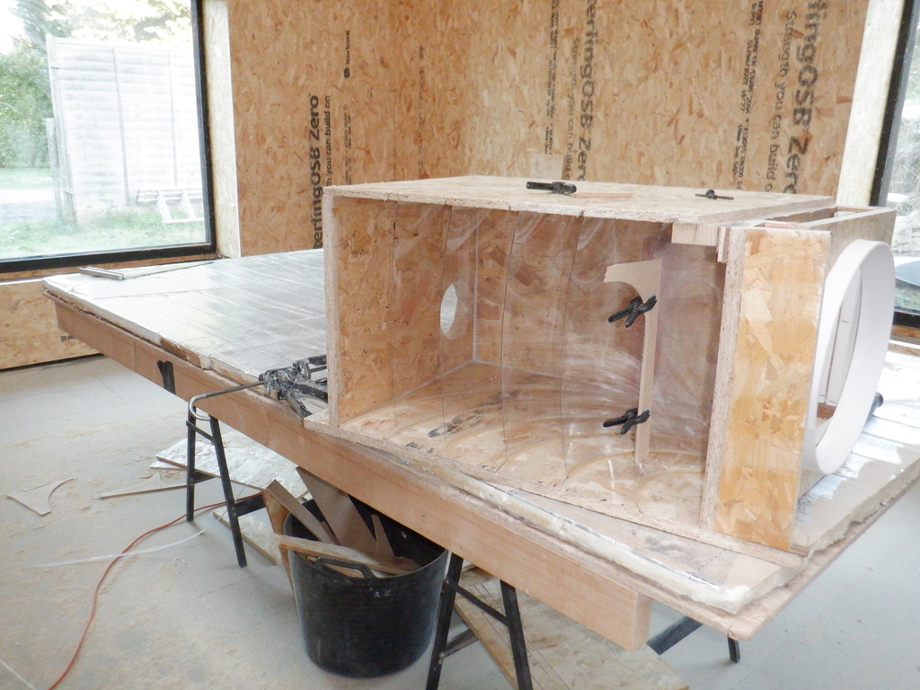
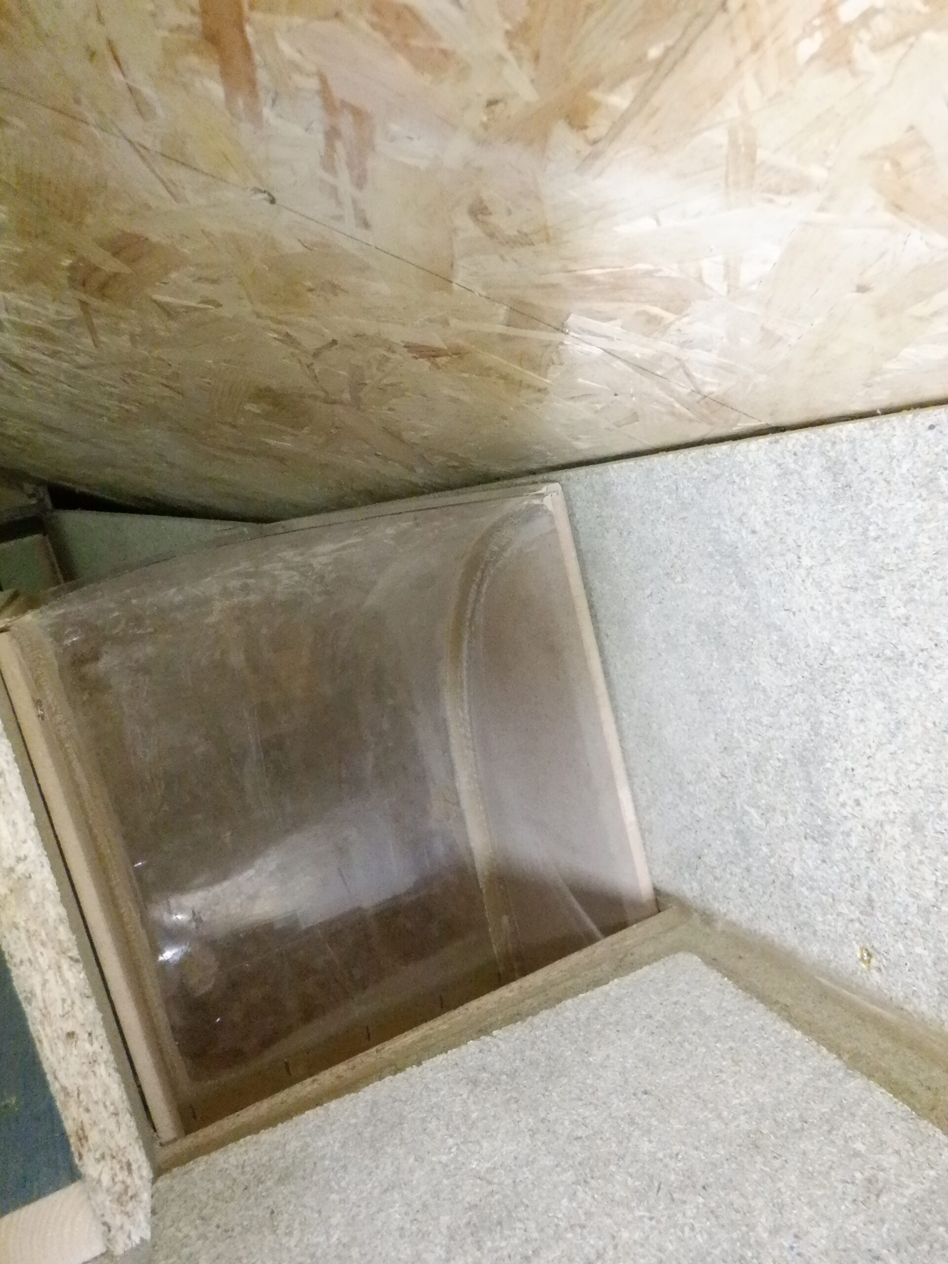
Redirect and Filter box with vanes installed
Now, we wanted to test fit the whole box module for real, up inside our Utility Cupboard, before we glue it all together and make sure that it fits as we planned. And, the result of the test fit was .. .. OK! At least, within acceptable tolerances. It is not perfect but it will do!
One thing we needed in this box, is a 100mm flexible pipe socket so that we had the capability of drawing air from inside our Utility Cupboard like for example, the Central Vacuum system and the Drying Cabinet. We glues on an extra 150mm square piece of 18mm OSB on the right hand side of the box near the bottom, and then proceeded to cut a 114mm diameter hole.
We also put in a “end-stop” on the inside of the hole, to make sure that the flexible pipe won’t crash right through and damage the internal curving vanes
We now can proceed to glue the lid on and apply glue around the inside corners of the box and screw everything tight. We then gave the whole thing a good thick coat of acrylic varnish.
After lunch, we glued in all six curving vanes with more construction glue and left that to set hard overnight. We then constructed the lid for the filter compartment, using two bolts and captive nuts to hold it down tight on a double circumference of draught excluder rubber strips.
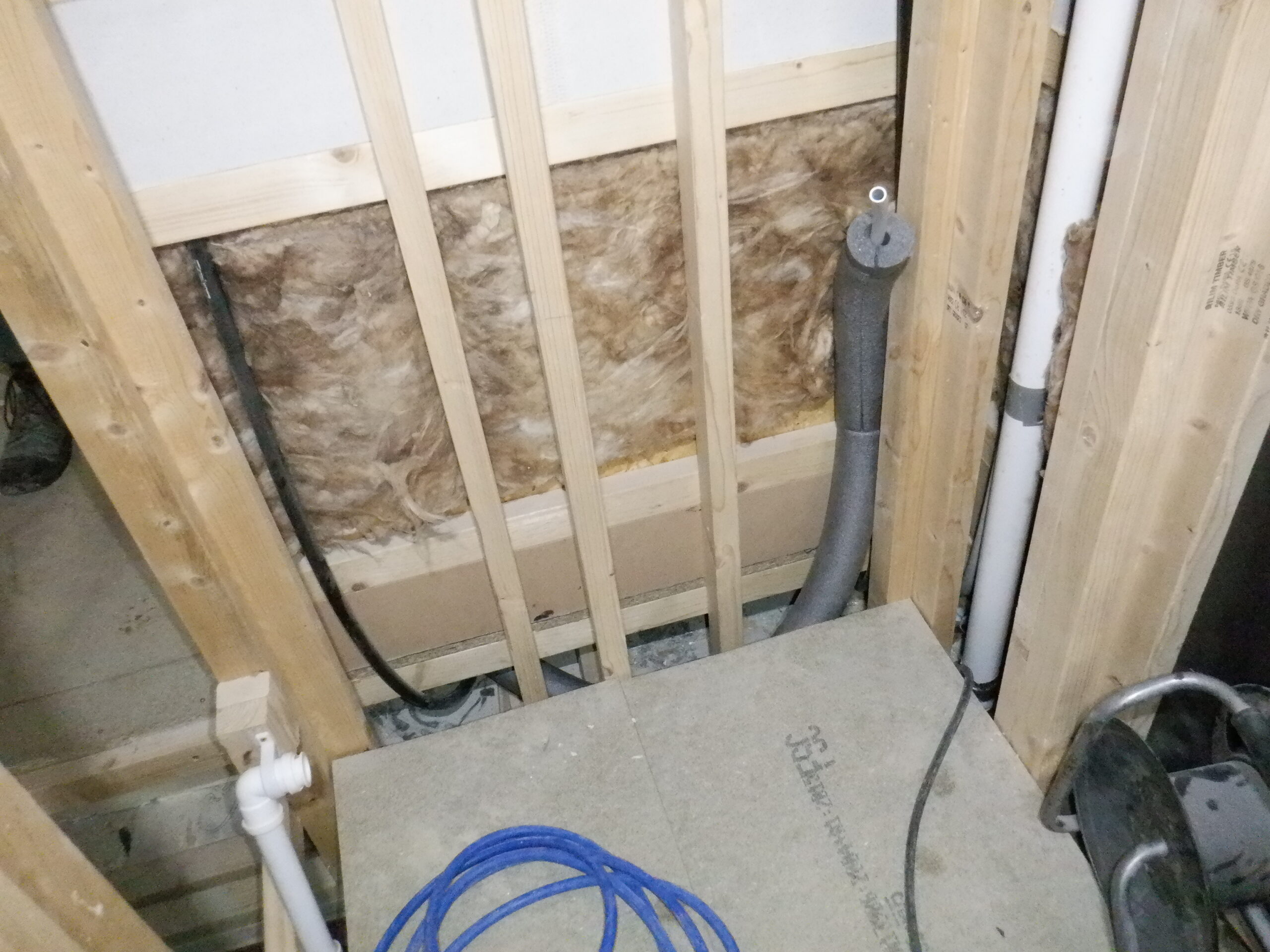
Next, we put the electric fan unit standing next to our divertor module on the floor (it being a nice flat surface) and made a couple of wooden battens for the fan to sit on. We happened to find an Oak piece of wood that was thick enough (27mm thick to be precise) and we prepared this batten with further holes so we are ready to mount the fan up on the wall inside our Utility Cupboard. We are using 50mm long coach screws with a hex nut heads, to make it easier to use an long extending bar to reach pass the bulk of the fan. We also used the same type of screws for holding up our divertor, one in each of the four corners, which we prepared as well.
Then, we manhandled it up onto the wall, aligning it up to the hole in the ceiling and applied a good thick dollop of construction glue around the rim of the divertor and pushed it hard up on the ceiling, and carefully drive in the four coach screws to lock it into place. It was the fan’s turn next and we got that up onto the wall as well, aligned it up to the divertor so that the circular adaptor joined together with the fan and also drove the screws home.
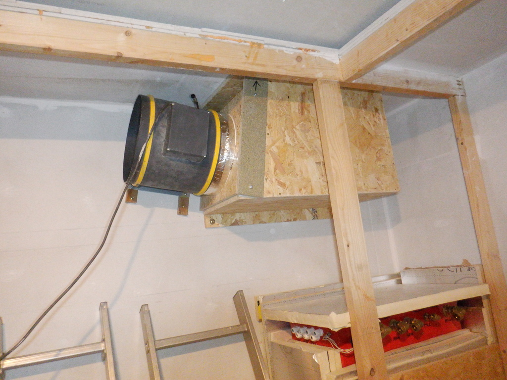
Redirect and Filter box installed
We did a quick test by plugging in the electrics and gave it a quick run at various different power levels. All our upstairs ducting all had air being sucked down the open ends, there were three open ends at the moment. We will measure the air flow rates later on but for now, it is looking very good. We did noticed that a section running through the ceiling space above the Front Door, at the bottom of the staircase, had an obvious air rushing noise but we do not have the ceiling plasterboard up there yet, and also the fan was running at maximum power too.
In the meantime, we carried on with the main airduct upstairs and we fitted our two new larger air vent covers that pokes into the Great Room, one at each end of the Gallery 8feet up. These air-vents are 310mm in width so we needed to cut a circular hole 270mm diameter using our jigsaw. We then sprayed in loads of PU foaming glue to stick the white coated metal into place, without having to use a cross bracket etc. We used a length of string tie to a large concrete block to pull tight the air-vent while the glue finished expanding and cured solid.
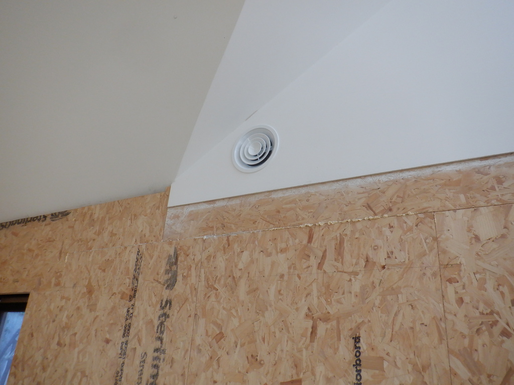
Great room waste air grill
We cleaned up the excess foam and fitted the inner white cones and we now have two white air vent covers in place.
The next job was to mount the metal air flow dampener unit (it has four rotating narrow vanes that opens, or closes, to control the amount of air flow), it measures 200mm internal air flow width but the whole thing including its flanges measures 260mm across and 70mm thick. We have three of these units, one for the air inlet on the left end of the Great Room, a second one for the right side of the Great Room and the third one for the ventilation coming from the Conservatory.
After considering the placement of the Conservatory side channel and where it will connect to the main ducting, we constructed the rest of the front portion of the duct going towards the Great Room where we located the metal gate valve. We had to make another circular adaptor, this time only 200mm diameter, to connect up the flexible aluminium pipe to the air vent in the Great Room wall.
We did the same for the other side of the building, to get the right side ventilation connected to its gate valve unit but we had a slightly more complex situation to deal with, in being very close to the chimney that is coming down from the Skylight. One of the thing we wanted to insert into the air stream, is a fir flow rate measurer, a temperature and humidity sensor as well. But we don’t have enough room for a removable lid and slide in a square module etc. So, decided that we would slightly rotate the circular adaptor by 20degrees so it pointing towards the vent sitting in the Great Room wall. Because the lid is relatively small, we decided to glue and screw it down permanently.
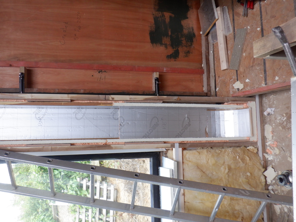
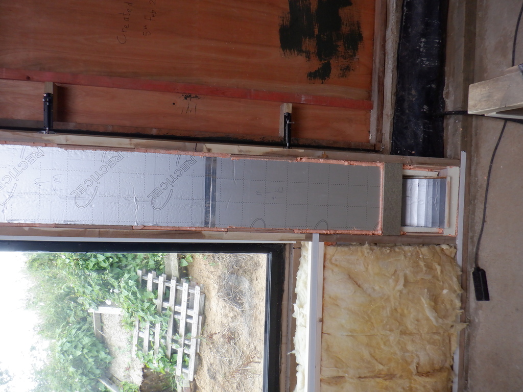
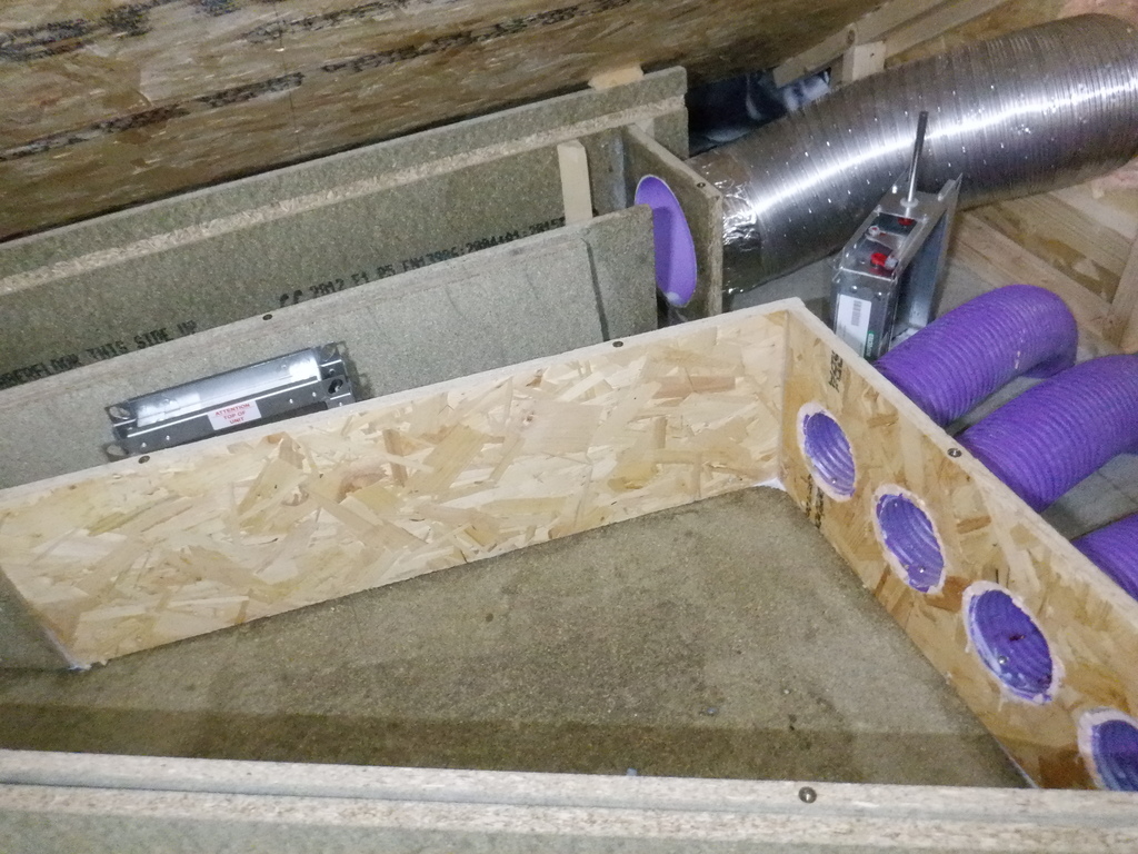
Then, we went back to doing the side branch of the ducting, for the Conservatory ventilation, coming through four purple 100mm wide plastic pipes. We bent them down and put all four of them into an single line, held in place with a block of wood measuring 260mm high and 600mm wide, which had four 114mm holes drilled into it. This in turn was screwed down onto the floorboard slightly angled so it is pointing towards the main air ducting. We established a good location for the gate valve and built a receptacle with more little pieces of 45degree triangle battens and then built up the back and front walls to and from the purple pipe adaptor. The last piece of front wall was extended with a little piece and that was glued and screwed into place too. Finally, two lids were constructed to cover up this side branch, held down with the usual metal bolts and captive nuts.
Great room and Conservatory waste air join main duct 1
Great room and Conservatory waste air join main duct 2
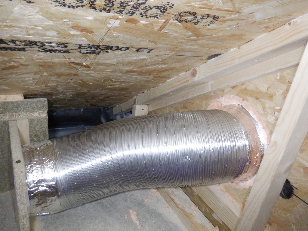
Then we tackled the fiddly job of putting on a flexible ducting, to connect up the Great Room vent to the end of the main ducting. We used 200mm diameter aluminium corrugated tubing, which allowed us to stretch and bend the pipe so it can transfer the air from the Great Room in a reasonably gentle way. The vent on the Great Room wall had only a 15mm lip to attach the pipe to, so we decided to assist this by sticking on lots of acrylic double sided sticky tape, going around several times this lip on the vent. We cut a 500mm length off our stock and managed to slide it on to the metal vent and pressed the aluminium hard down into the thick sticky surface. We reinforced this joint with two 400mm long plastic cable ties to hold it tight. But, it was quite a struggle to pull and stretch the tubing, and then bending it over so that it can slide onto the circular adaptor we made sticking out of the main ducting. We eventually got there without ripping the aluminium foil that this tubing is made of.
We stuck it into place with lots of aluminium sticky tape on both ends.
Great room connected to waste air duct
To finish this very long drawn out task of building the Waste Air Ducting that has stretched across many months of elapsed time, but only a few weeks in actual work time .. We built a curving divertor for the second chimney coming down from the Skylight and built a boxing around the hole in the ceiling. It is a repeat of the first chimney we did earlier, but it was a little bit simpler this time, not having a diagonal valley beam intruding.
Waste air chimney joins duct @M end
While we are doing this particular job of building the ducting, we thought we had better do one of the final jobs, which is to varnish the internal surfaces of the air duct, especially along the floorboard surfaces. So, we unscrewed all the lids, then vacuumed every inch and painted a good thick layer of acrylic varnish on all exposed wooden surfaces, to help seal it against moisture and reduce the chances of unwanted biologicals gaining a foot hold.
With removable lids, we can inspect any part of our ducting and give it a thorough clean every now and again.
Testing and Results
So before we put the lids back on, we then tested the flow rates in various positions with our new portable anemometer and seeing what volume of air we can generate. We wanted to learn to how much air the fan is able to pull, with and without the filter, with and without long ducting so we can detect and appreciate problems, and fix them if we have any.
We deliberately blocked one half so that we could measure the air flow down along one ducting journey and learn how the air flow rates changes. We did the same in the other half of the system.
We started at the beginning, immediately just above the Utility Room and measured each side just at the point where the ducting is turned downwards. We left both sides unblocked, and we also took out our filter which is situated just before the fan downstairs in the Utility Cupboard. Our new air flow measurer, can calculate the volume of air movement in real time, so long as we had supplied the cross sectional area of the ducting we are measuring. For example, the “holes” on either side of our divertor, measures 230mm wide and 180mm tall, which makes a cross sectional area of 0.041 square metre. The meter needed the final number in square metres, hence the fractional number. Then we got a series of readings in various bits of the air flow, and calculated the average between those readings. The very clever hand held meter also performed this calculation as well!
Here are the results:
- Right side (no filter) – 15 cubic metres per minute (m³/min)
- Left side (no filter) – 31 m³/min
- Right side (with filter) – 12 m³/min
- Left (with filter) – 22 m³/min
If we combined the figures for the “no filter” mode, we get an accumulated value of 46c.m./min and if we multiply that up to cubic metres per hour, which is 2760 cubic metres every hour, this value is very close to the advertised performance as specified by the manufacturer. This is very good !!
By the way, we are deliberately running the fan at maximum power, just to see what we can get. It is more likely that we will be dynamically controlling the fan speed all the while, and keeping it as low as possible, while fulfilling the demands that each room is wanting.
Then, we proceeded to block each side and see what the new flow rate was on the other side .. as follows:
- Left (with filter) – 28 m³/min
- Right (with filter) – 25 m³/min
So leaving one blockage in place, on the left side, so we could test several parts of the ducting, going along the front of the house, as we put back the lids again. We measured the flow rates and it seems to settle down to about 23 m³/minutes by the time we reach the Great Room vent and the side branch that is going off to the Conservatory. That is not too bad!
Then, we went around the other half, putting back the lids and measuring the flow at various points, and we were getting a value of 28 m³/minute.
It really didn’t start dropping off until we reached the far end, coming up to the other end of the Great Room. We were reading a value of 20 m³/min. which is not surprising considering how long our ducting is!
And finally, we tested the two chimneys going up to the Skylight and they gave a flow rate of 18 and 20 m³/min for the South chimney and North chimney respectively.
This concludes most of the work upstairs for the main bulk of getting the waste air drawn out of our house. There are little jobs left to do upstairs but we will do those later. We want to start on a different job!!