It was another day of working in the Workshop while the cold rainy weather front slowly drifted down from the North. Today, we created the Parts that will make the Corner Posts for the External Wall.
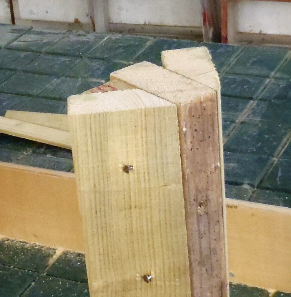
These posts have three parts to them, two “wings” joined onto a central body, looking like an “arrow”. The orientation of the body part is at different angles, depending on where on the roof that post is situated. We got the computer to draw and calculate the angles and print the results on paper for us to refer to and tick off each corner as we have done them.
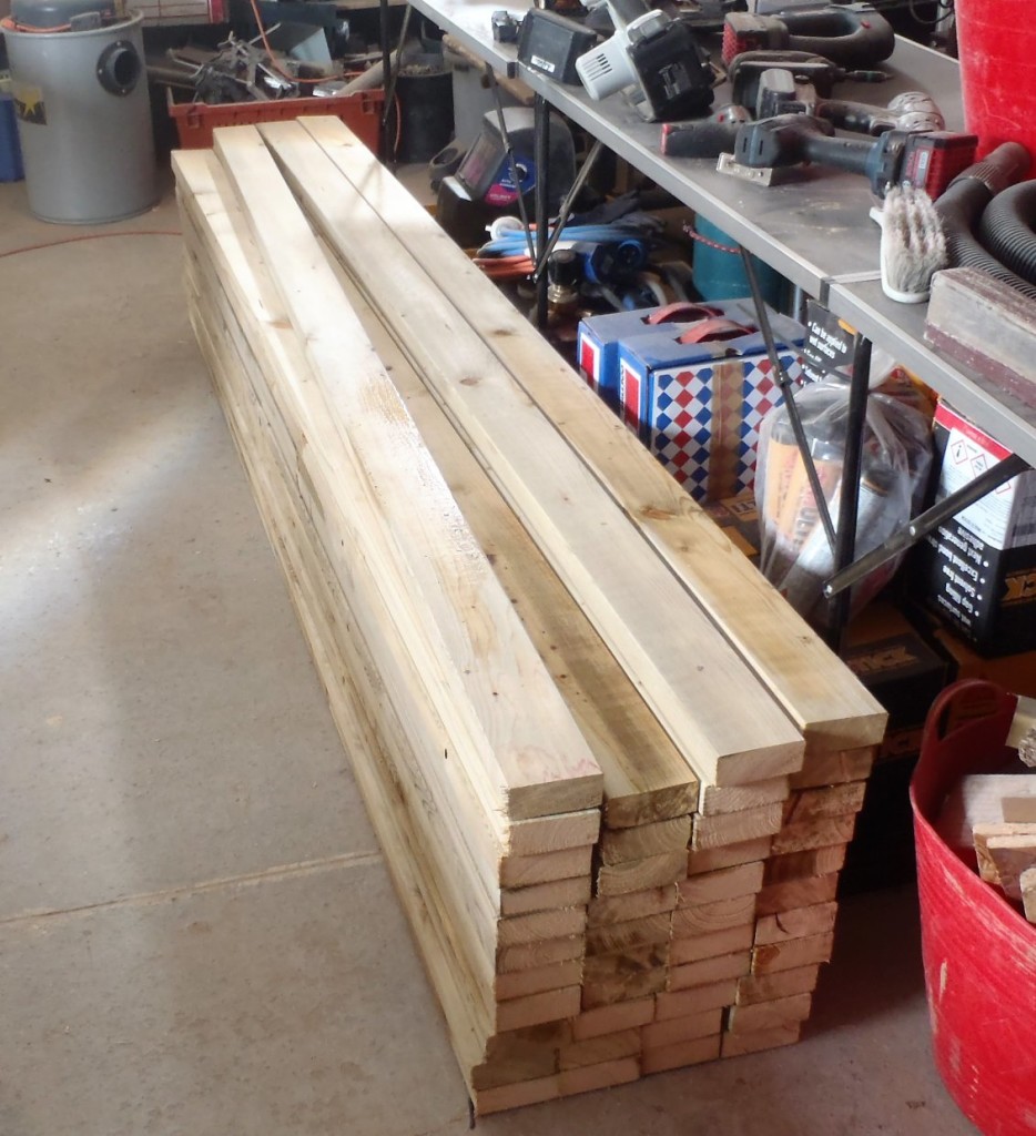
But first, we collected another 20 lengths of the 89mm CLS timber from our pallet and chopped them more or less in half. This and the 3 odd ones we had leftover from yesterday, we now have 43 pieces ready for the next stage.
Then, we made some improvements to our Modular Workbench System by putting in locking nuts and bolts onto our fence strips. We wanted to lock down the fence so it couldn’t wiggle or ride up during any operation we might be doing. Every position of the fence needed a nut to be installed into the surface of the work top (a total of 20 of them) and the fence has 2 bolts to screw down where ever it is located.
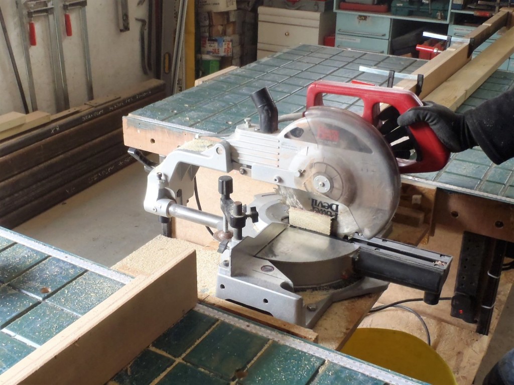
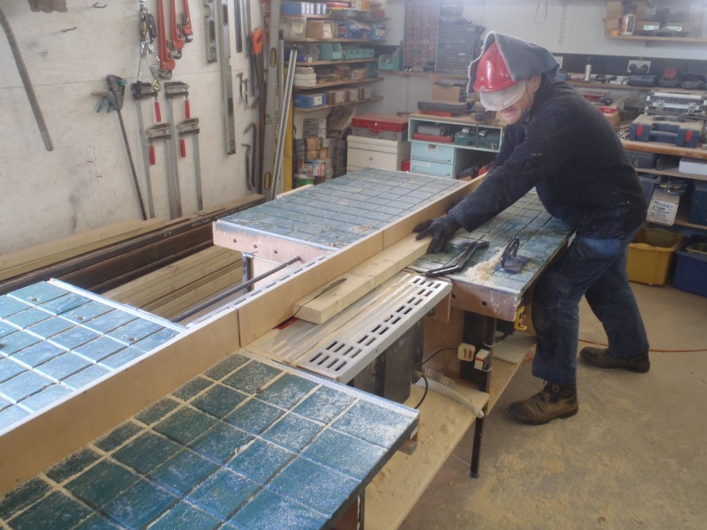
After lunch, we slid in the circular saw module and tilted the blade over to various angles to rip cut down the lengths of the 89mm CLS pieces, according to our printout. Each Corner Post has these wings that attached to the central Body and it is the central Body that is angled each time depending on its location around the wall and the roof it is supporting.
So for example, if the body part needs to be set at a 33° angle, then the two wings has to have the corner bits sliced off, one is a 33° bit and the second wing will have 57° sliced off, so when these two wings are combined together , they form a 90° right angled corner (33° + 57° = 90°).
The trick is to pass through the circular saw, one piece of CLS timber lying flat and the another CLS piece going through vertically, making the two opposite angle cuts without having to adjust the saw blade each time!
We tested this technique out using short bits and glued and nailed it together as you can see in the photo below.
The 12 corners have the following angles:
- 2 x 33°
- 4 x 36.5°
- 2 x 40°
- 4 x 44°
We have created the 12 sets of the parts, ripped cut down too length and ready for the next stage. The next stage is rather tricky, as we need to place these wings onto the central body part, glue it using our non-creep structural wood glue and nail it together to hold it while the glue dries and cures. We made two little jigs to form right angled templates to hold the three parts together whilst being fixed.
This will be quite fiddly so we need more practice and learning how best to do it. That’s the job for another day!


