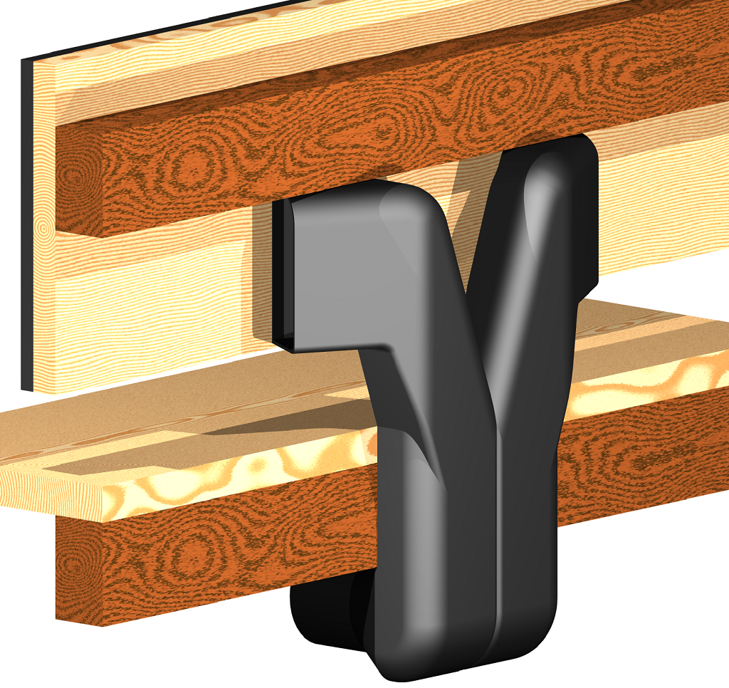
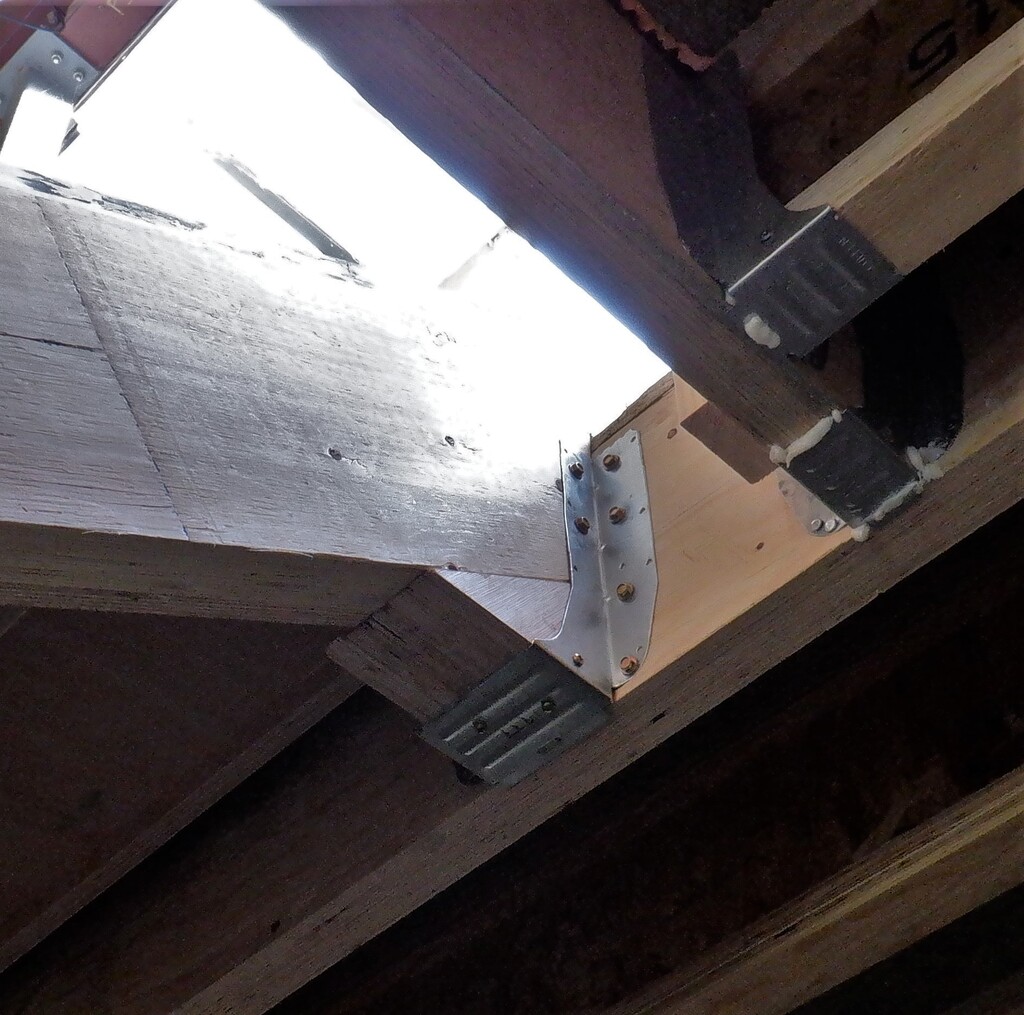
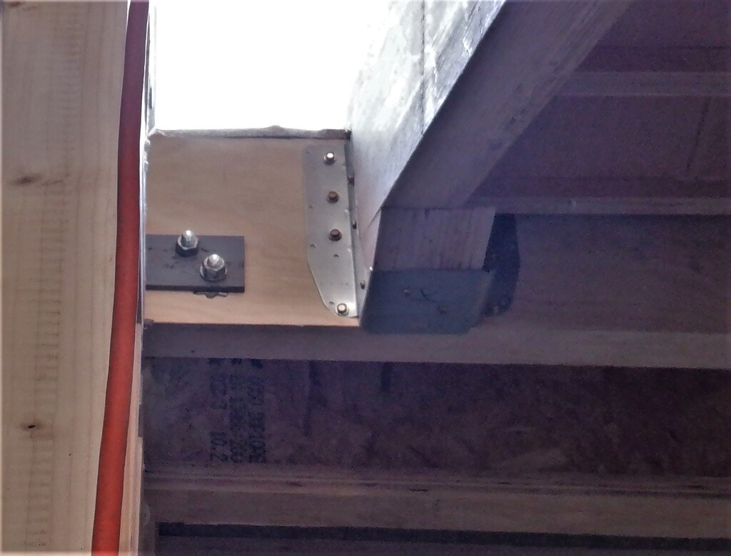
We started the new week, after completing our staircase in just four days, by fixing up the metal joist bracket to the stringers at the top of the stairs. We had already made two triangle wedges and they were glued in on Saturday. The metal bracket was only screwed up this time because we want to have the possibility of moving the whole staircase when we come to install our stair lift module later. We are not sure yet whether we will have enough space either side of the stringers to mount cog wheels and other materials to build the parts of the stair lift. So the joist bracket are just screwed on and not glued ..yet!
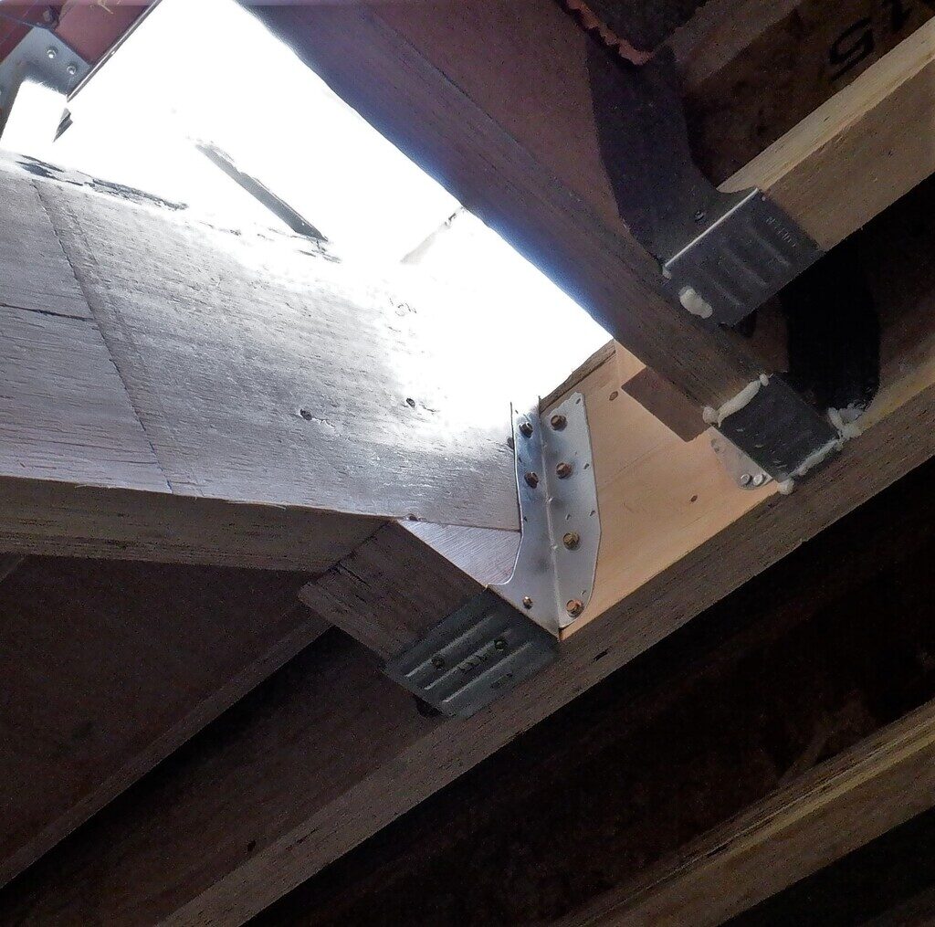
Bracket-holding-up-stairs-1

Bracket-holding-up-stairs-2
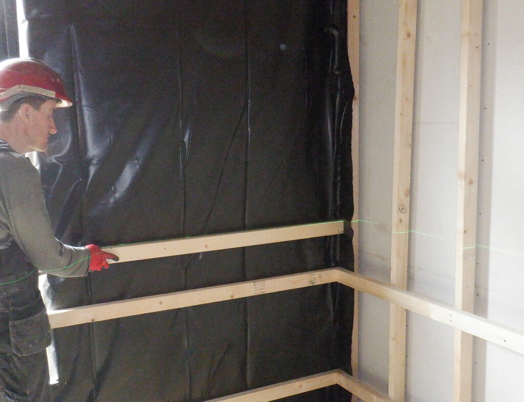
So onto the flooring job, we got out our green laser line generator and sat the device in the middle of the crossroads of our hallways and adjusted the height until we got the green line shining right on the 10metre mark, this being our Ground Zero line. We already had an 11metre mark on the metal leg “number 5” that is our reference point for the whole house so we measured down one metre for our ground zero, this will be our flooring level for our ground floor. We now have marked all the doorways (Kitchen, Great Room, Bedroom 1 & 2 & 3, Entertainment and Utility rooms) plus every other wall posts everywhere in range from the hallways, also doing the smaller rooms (toilet, tech and knick-knack cupboards etc) plus the front door and stairs too. We want to be able to place our laser line generator in each room separately and get the floor height exactly the same all over the house when we get to do that room.
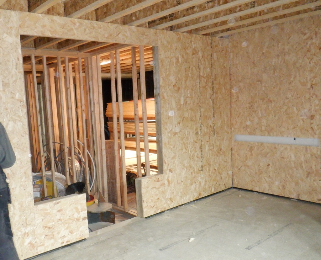
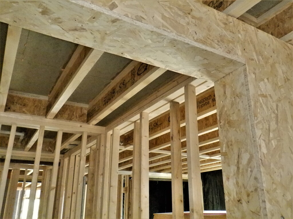
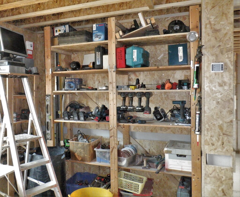
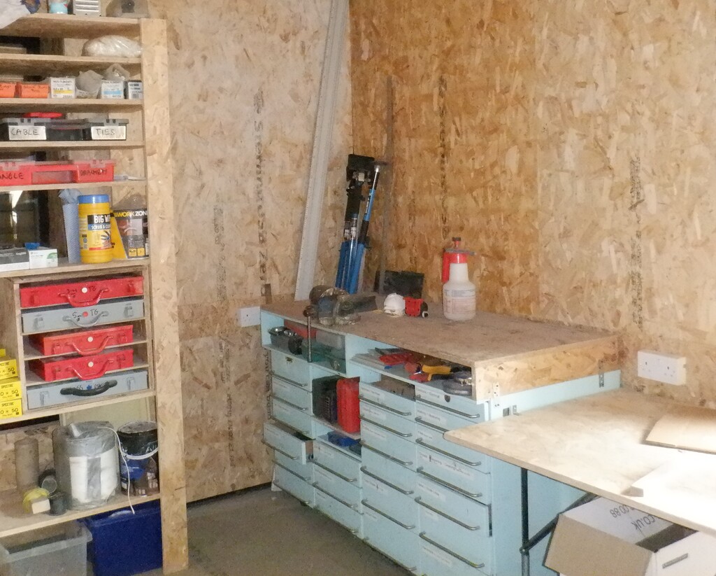
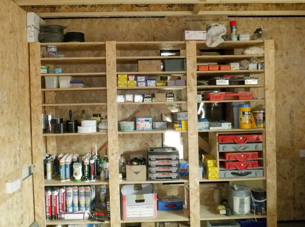
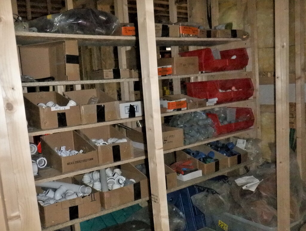
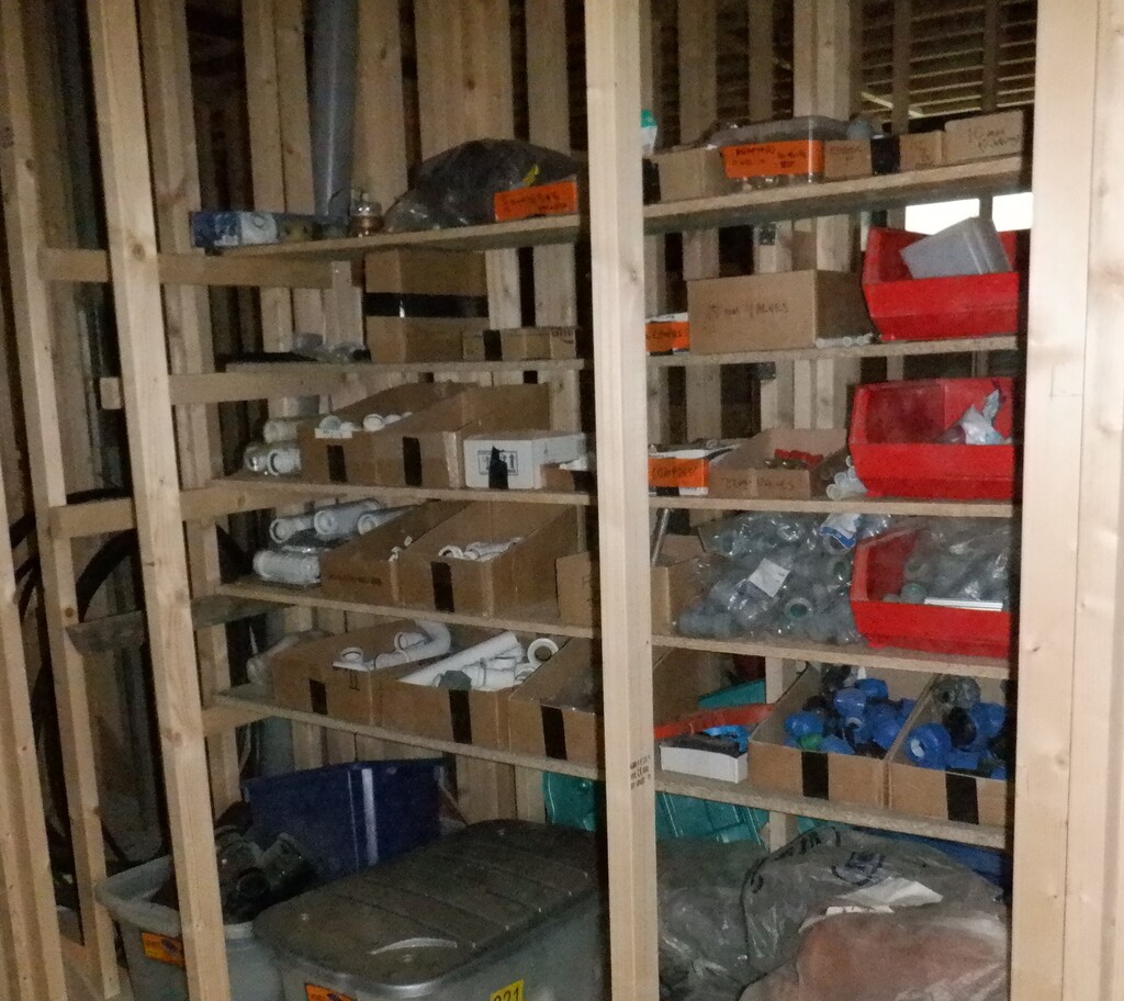
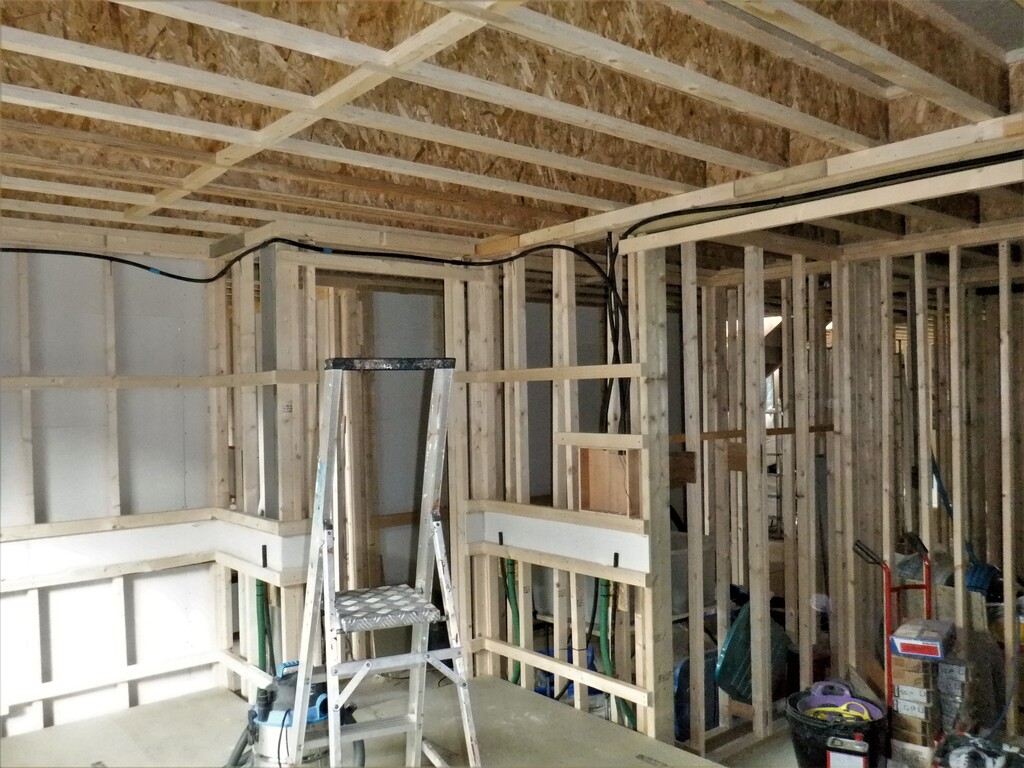
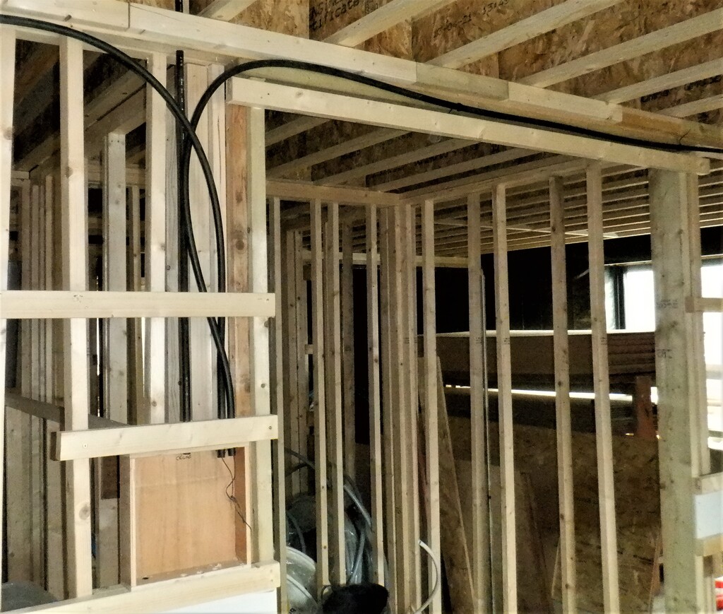
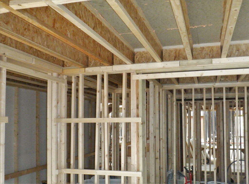
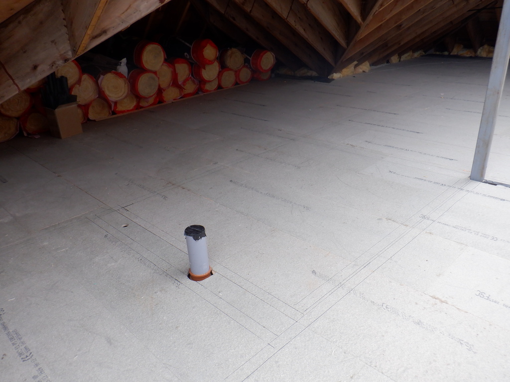
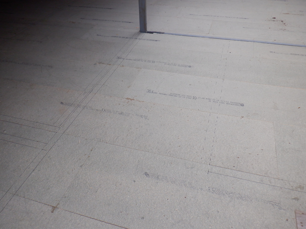
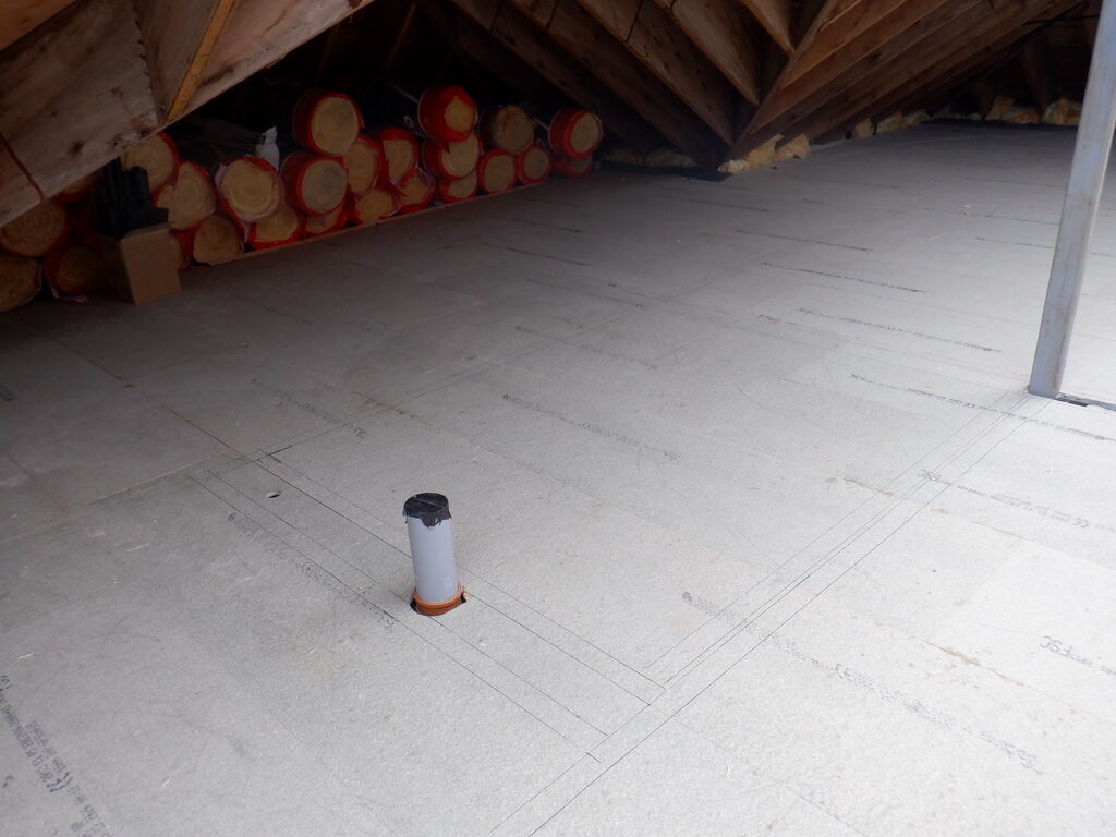
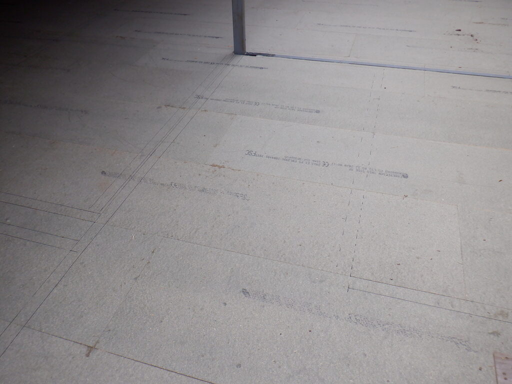
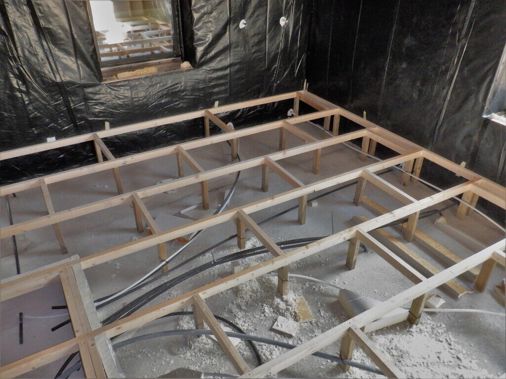
One of the first things we needed to do, after doing the laser calibrations, was to empty the content out of each room we want to work on, so in Bedroom 3 we had to move our solar water tubes and a heap of ladders etc. so we decided to move them, the solar tubes to our new storage area, mainly the first floor and its great expanse, to get them out of the way for the time being. But first, we felt the need to be a bit careful and clever, to position these items upstairs so they don’t impact too greatly on us working upstairs like building walls etc. To this aim, we marked out an outline of each room and their walls, these being the Creative room, the Study, the Workshop and the toilet plus all the “triangular voids” spaces and the large storage space behind the toilet over the top of the back rooms of the house.
First-floor-rooms-marked-out-1
First-floor-rooms-marked-out-2
Then, we moved the six crates that holds our one hundred solar glass collector tubes from Bedroom 3 to upstairs and placed in the Study over the Entertainment room and front door. The heap of ladders etc. were moved to sit underneath the new staircase.
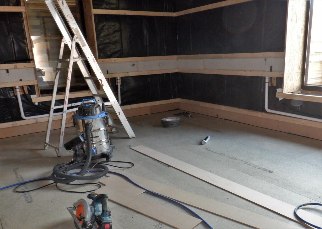
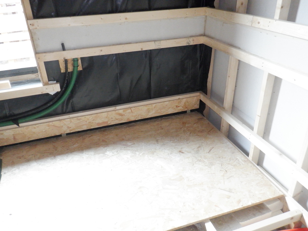
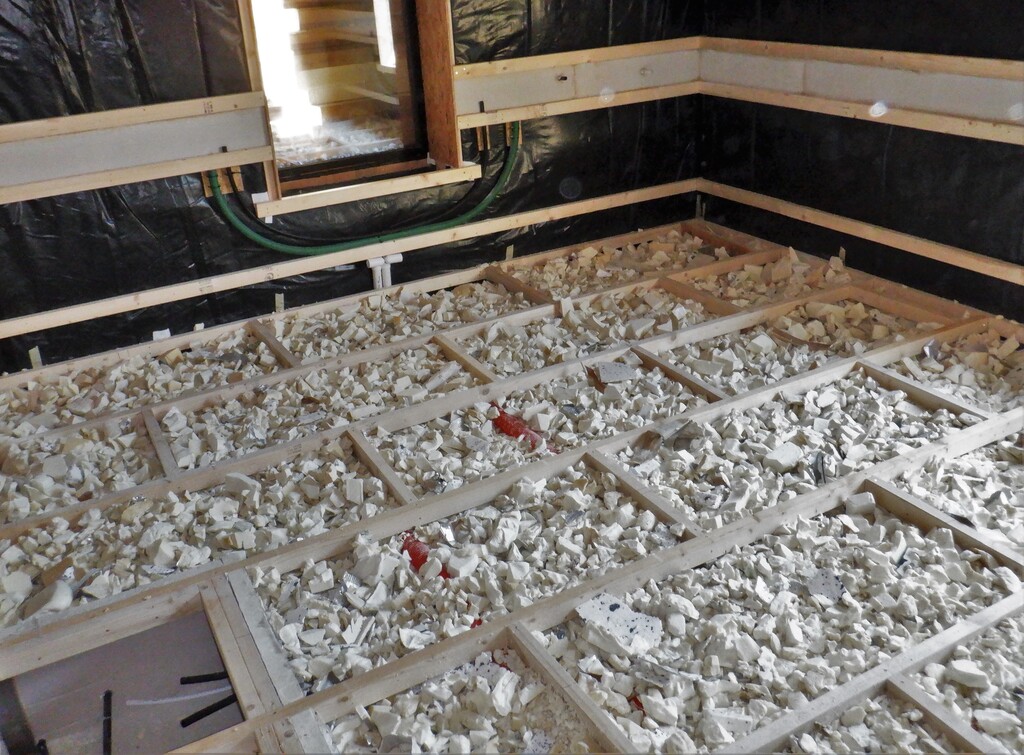
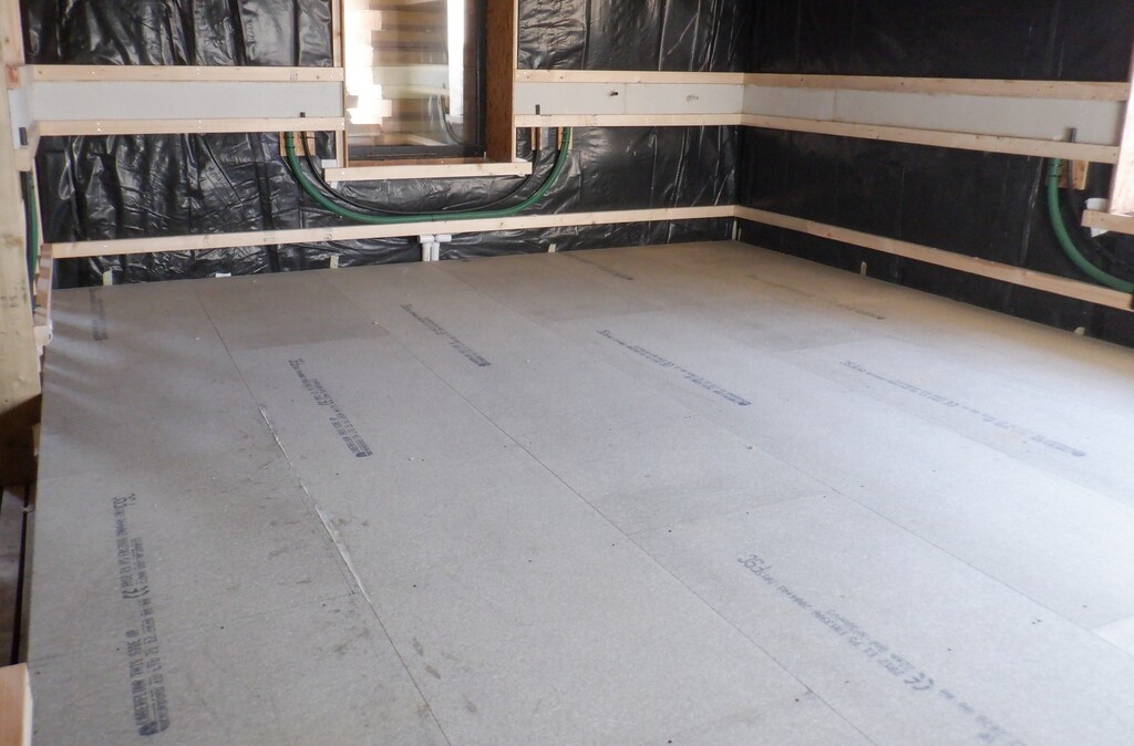
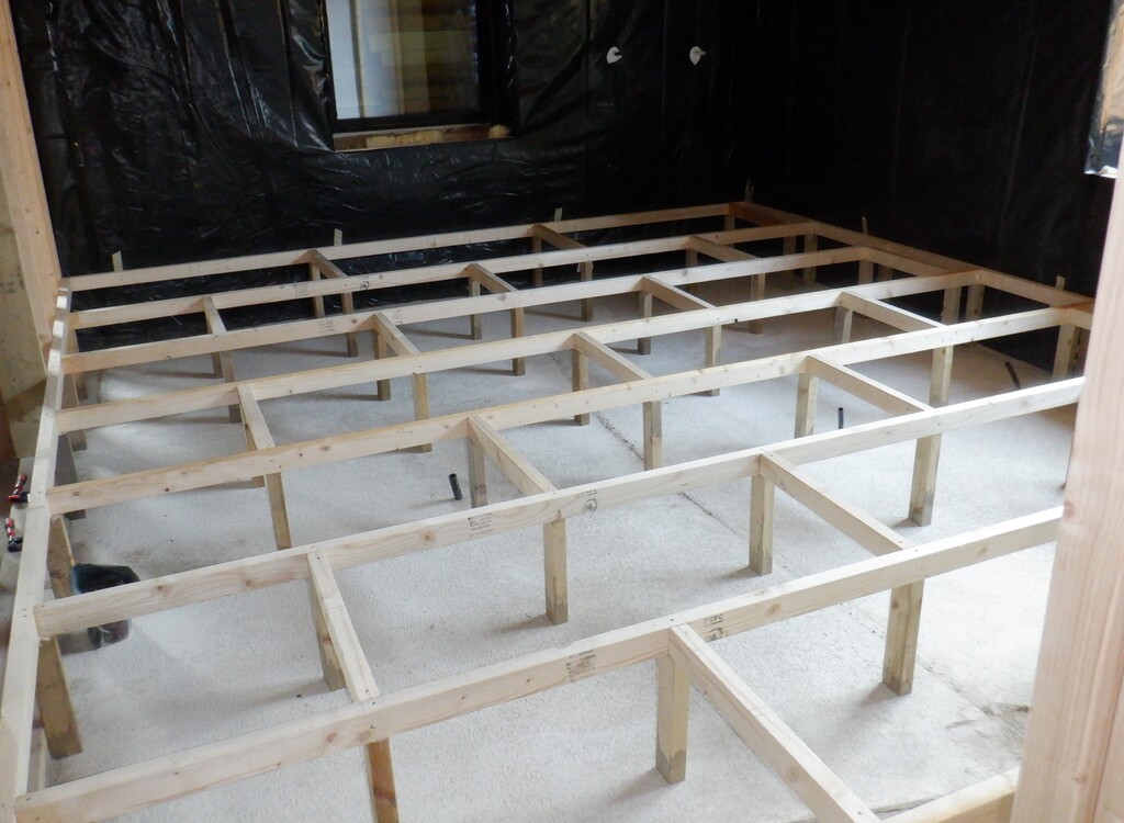
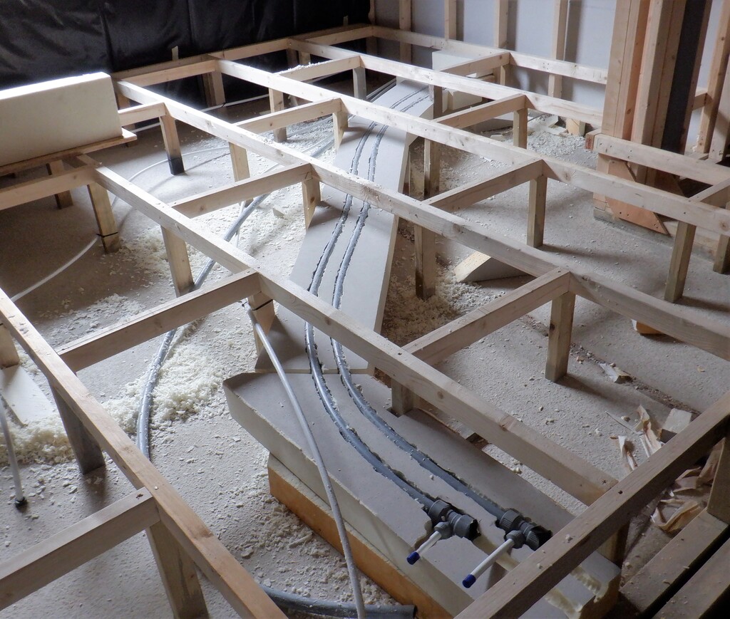
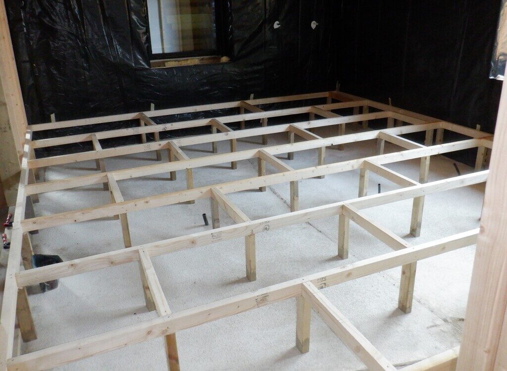
This meant that we could and did get on in constructing the flooring for Bedroom 3 (the one next to the Utility Room) and got the laser to shine a green line right around the room, aligned to the reference marks at the doorway and carefully marked all the vertical posts and stuck masking tape on the black plastic to see the mark there too. Then slicing five lengths of our usual 63mm CLS timber, we nailed up a perimeter of a support framework that will hold the 22mm thick floorboards when we are ready for them to go down. The room is arranged in a grid pattern with 600mm spacing between the contiguous joists and an alternating noggings in every 1200mm in the opposite direction.
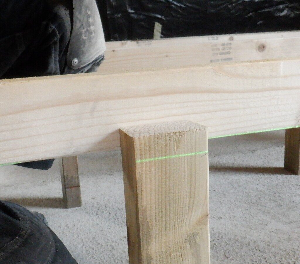
We built a little laser hanger gadget that hooks on to the perimeter rail so the green light will be exactly the height of all the legs supporting all the joists and noggings. We cannot just simply measure the distance from the concrete floor surface, up to the underside of the CLS joist because both the concrete floor and the wood slowly rises and dips in random directions, hence this little clever hanging gadget to position the laser line generator to shine its green line against each set of legs to be trimmed.
Laser-marking-leg-heights-1
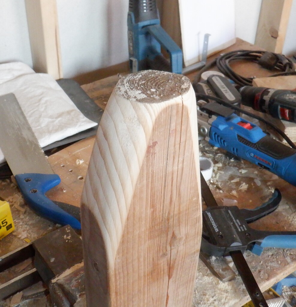
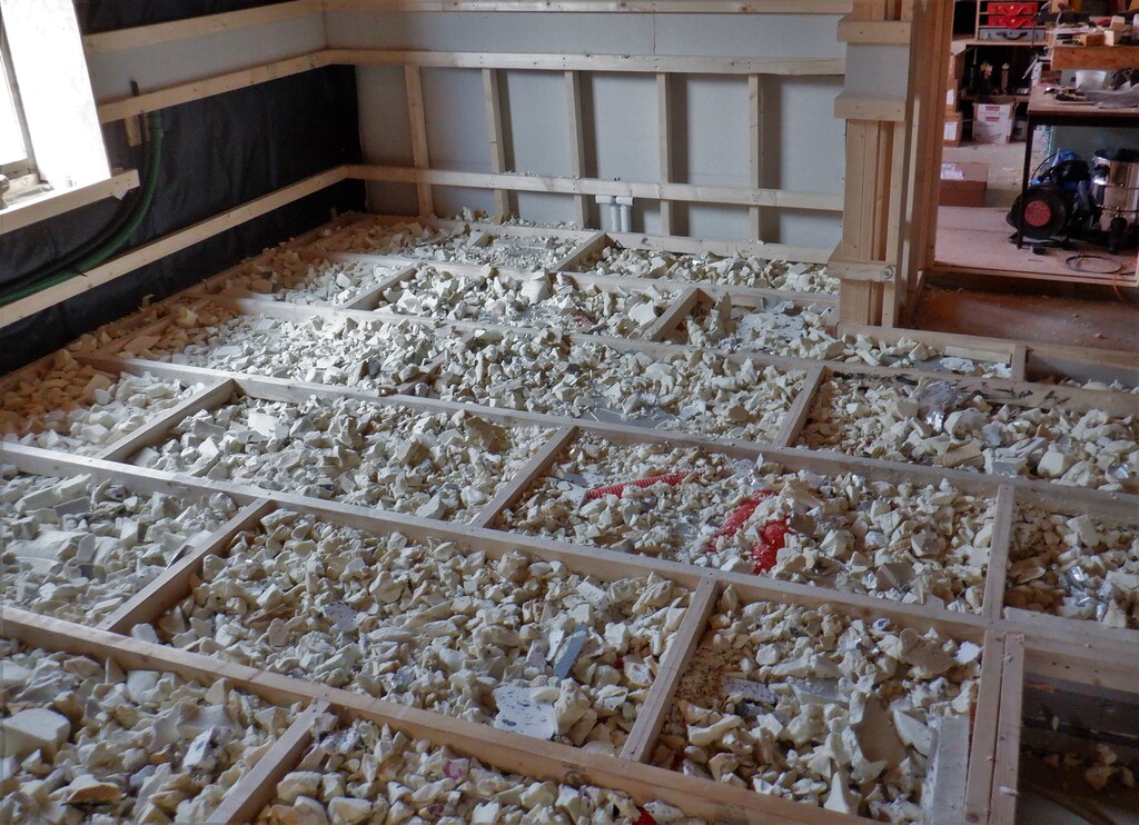
We are using our left-over treated timber for our legs, plus dipping the cut ends into more preservative treatment, all to protect the wood from rot if we ever got a flood under our floor, we don’t want to find that our flooring supports started rotting after a decade or two and find our floor sagging. So we are dipping the cut ends into a trug that has black died preservative and therefore we would know which end to put downwards.
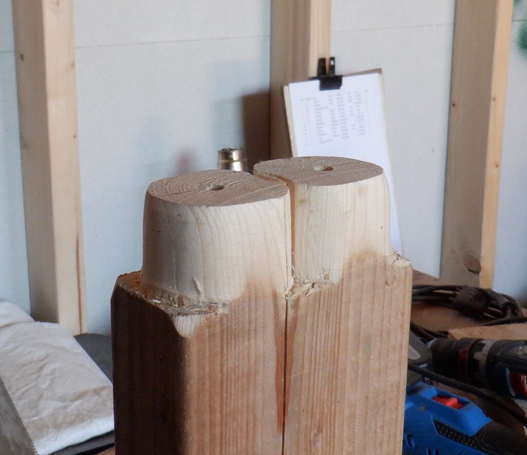
But these little legs are only 63mm wide (by 38mm in the other dimension) so aligning the leg underneath the horizontal joist (which is also 38mm thick) would poke out only by 25mm. This is plenty enough to support noggings but only on one side at a time. This means that we staggered the noggings in each row so the whole room is evenly supported across the floor.
Bedroom3-Floor-supports-in-place
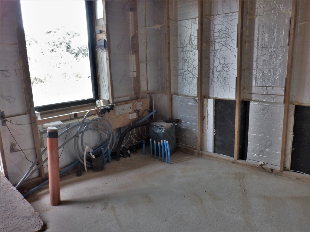
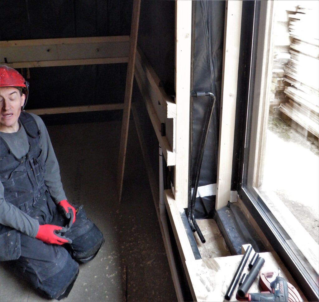
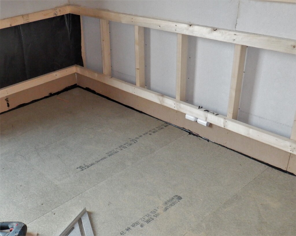
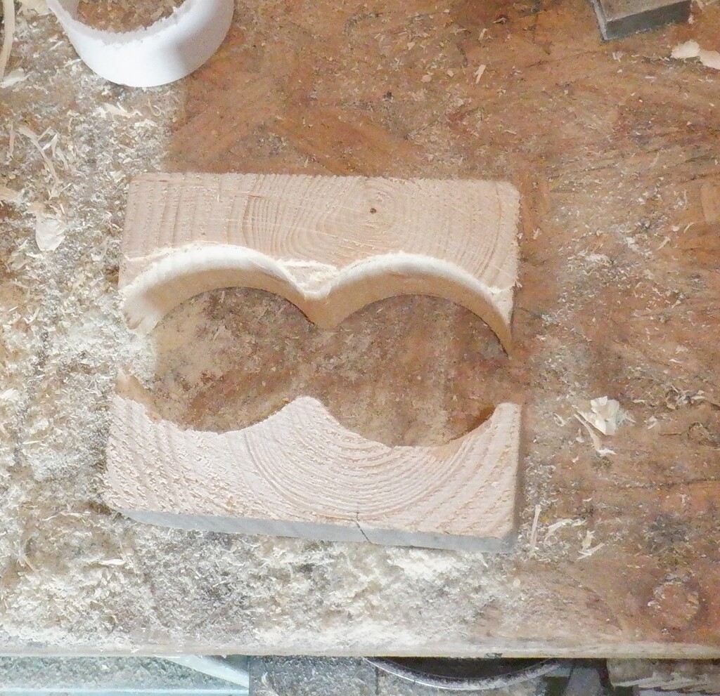
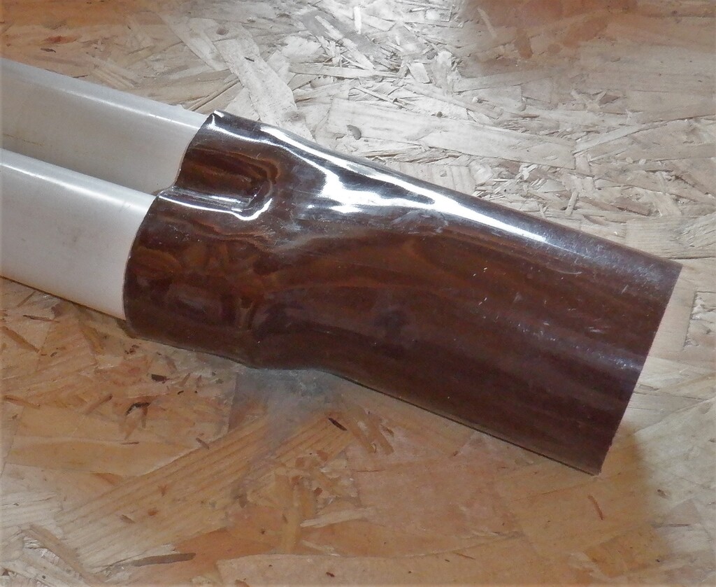
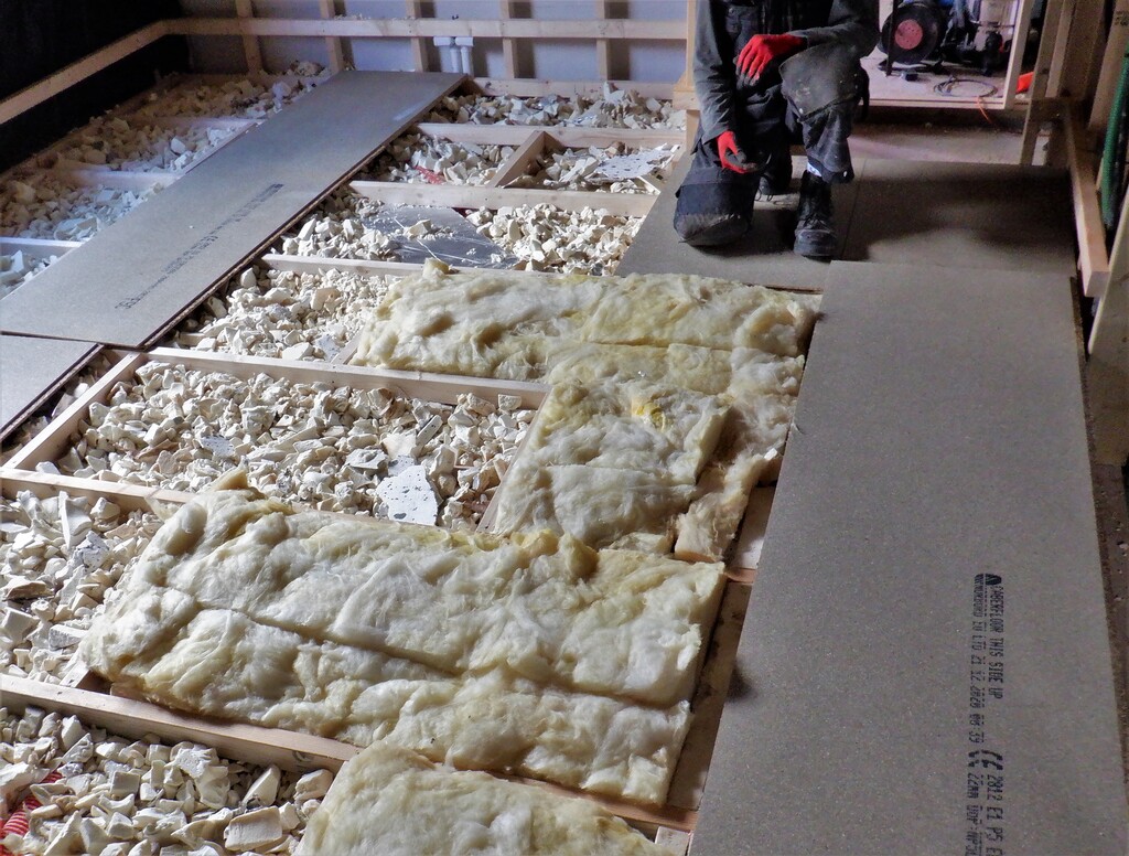
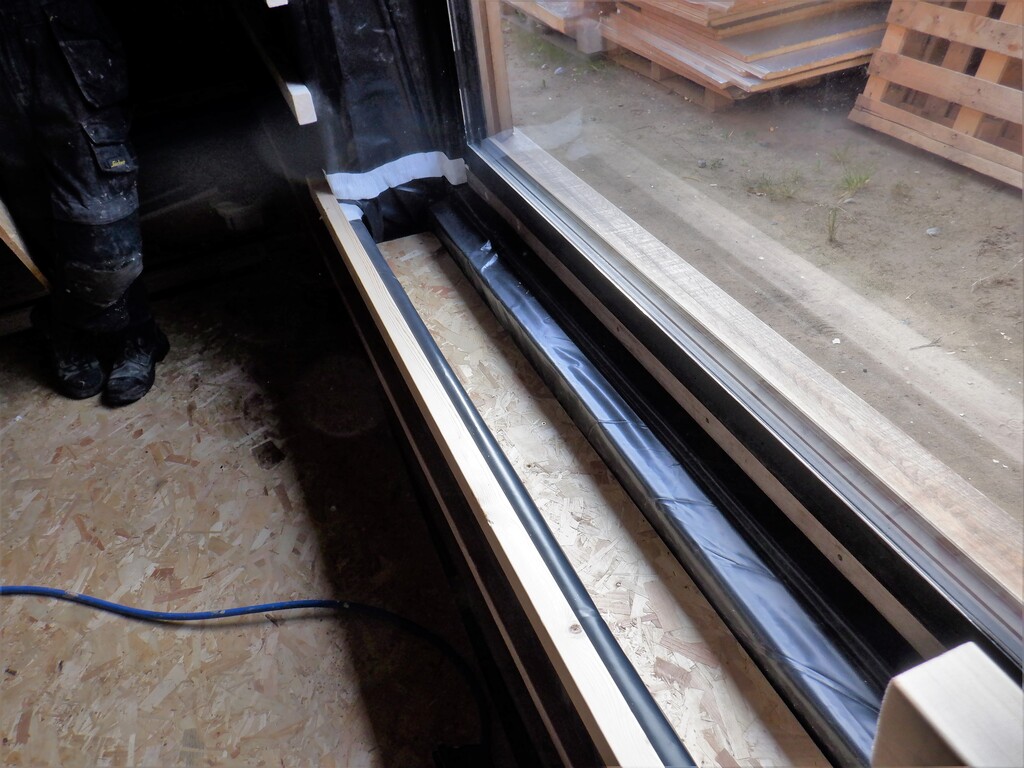
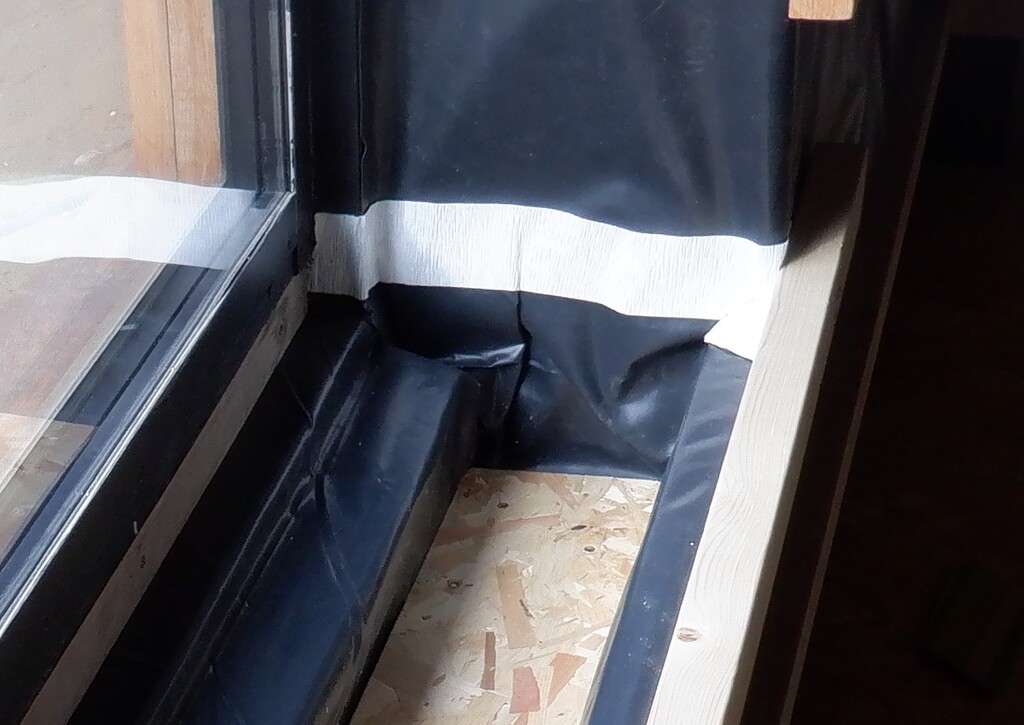
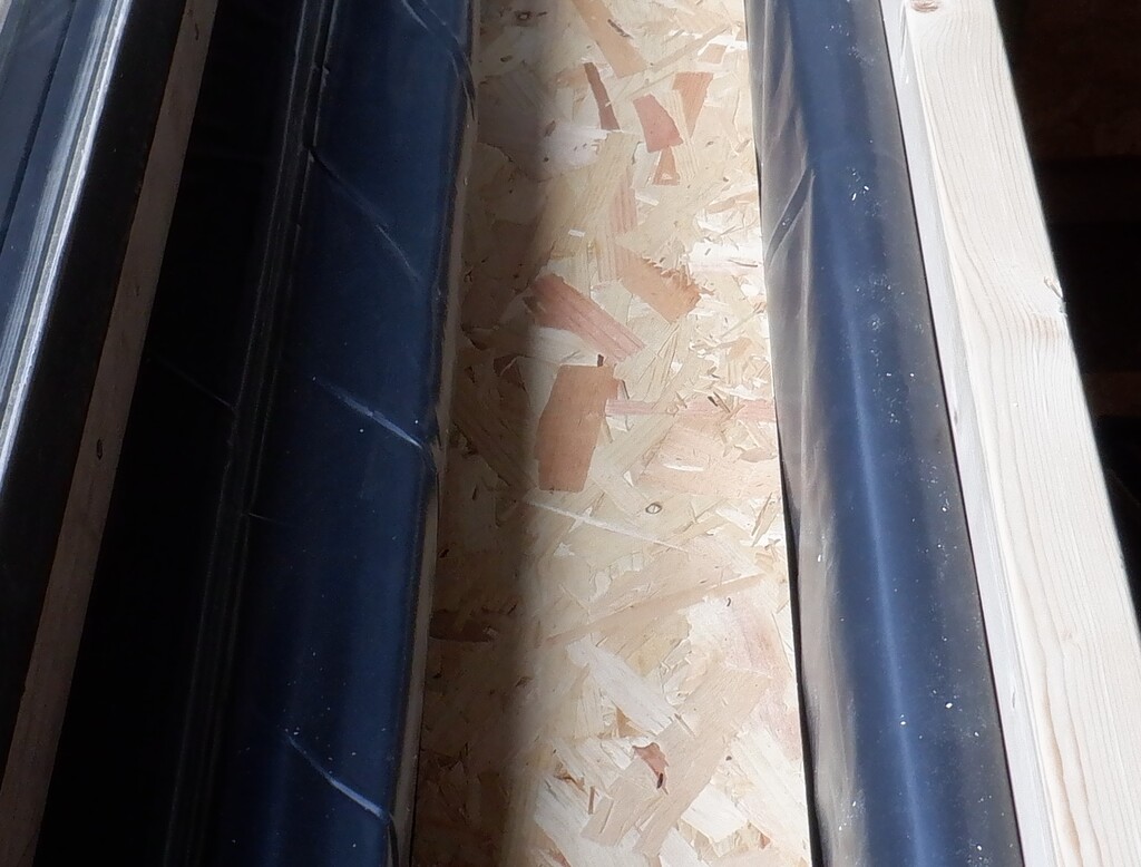
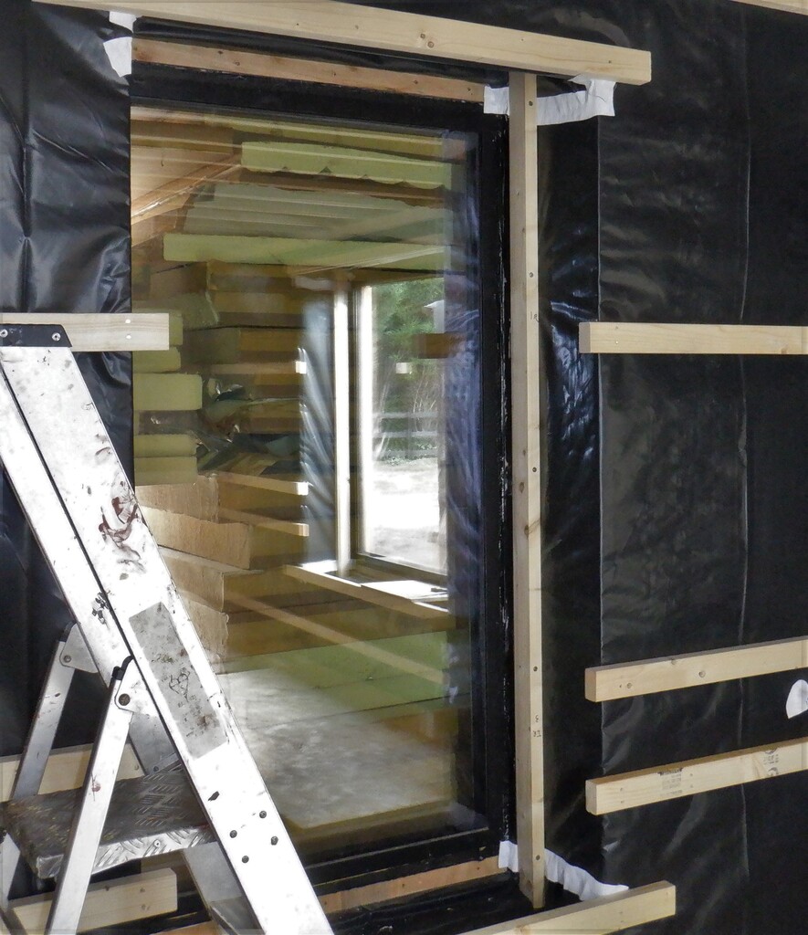
The next job was to sort out the bundle of water pipes and cable conduits that runs across the room, from the external walls, from underground and passing through from the Utility room. We did the hot water pipes first which comes along from the Utility in 28mm pipes and curves towards the en-suite. We had always planned to have 28mm diameter pipes, to hold a high volume of water flowing throughout the house and also we wanted to constantly keep this hot water supply hot and active, ready for any demands. This means that we have two hot water pipes running alongside each other, a “flow” and a “return”, just like in a traditional central heating systems. But we recognised that there could be a good deal of heat loss, and money, in a constantly circulating system, losing energy around the loop all the time. So to this issue, we put down two layers of 100mm thick PU foam boards, sitting on the concrete and cut a slot in the top of the second layer for the 28mm pipe to sit snugly in.

Bedroom-3-Hot-water-pipes-layed-in-insulation
Then a 90mm thick “lid” went over the top that brings it up to the underside of the wooden floor supporting framework. The rest of the space on either side will also be filled in with more insulation so this hot water system will be as protected as possible against heat loss and provide our whole house with quick supply of hot water when we want it.
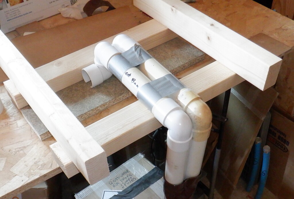
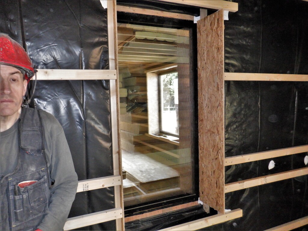
The cold water is also supplied in a 28mm diameter pipe but that is running “loose” nearby the hot insulated pipes and all three are routed to arrive just outside the en-suite doorway where we will have a liftable panel cover to gain access to the various controls and devices to condition and supply the water needs for the basin and shower in the en-suite. We built an extra framework around this area to support the “lid” and also inserted vertical PU foam boards to act as a barrier to keep the loose insulation in the rest of the room from “leaking” into our inspection and servicing chamber.
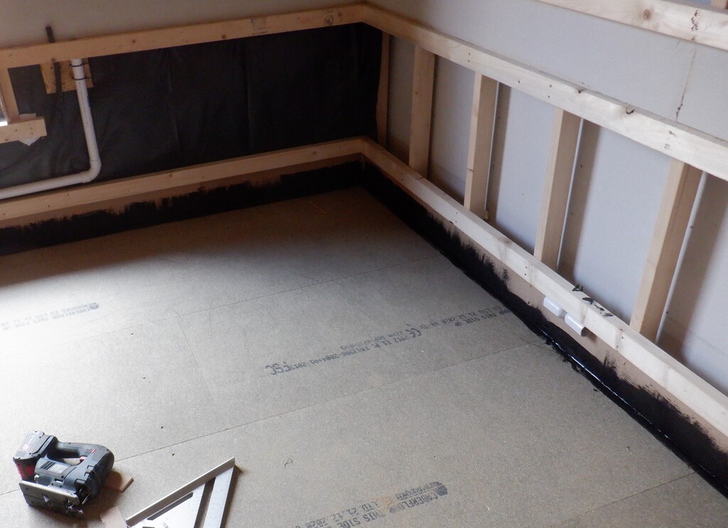
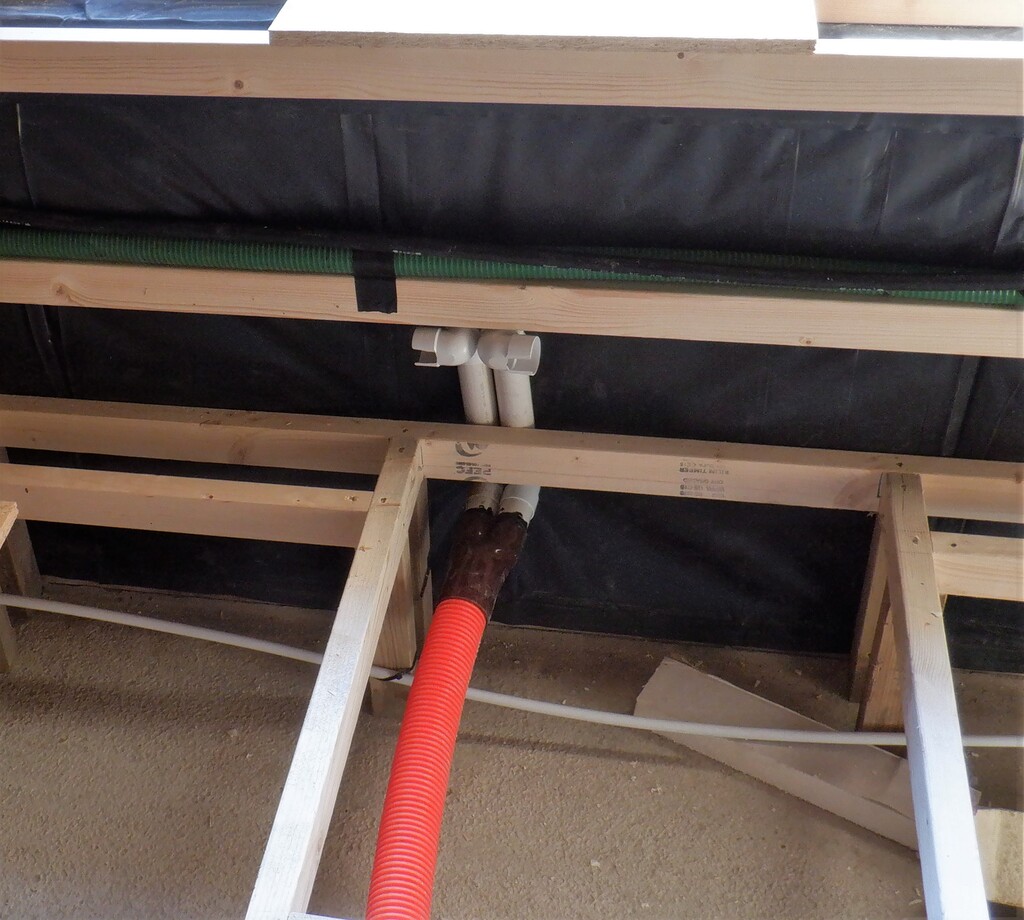
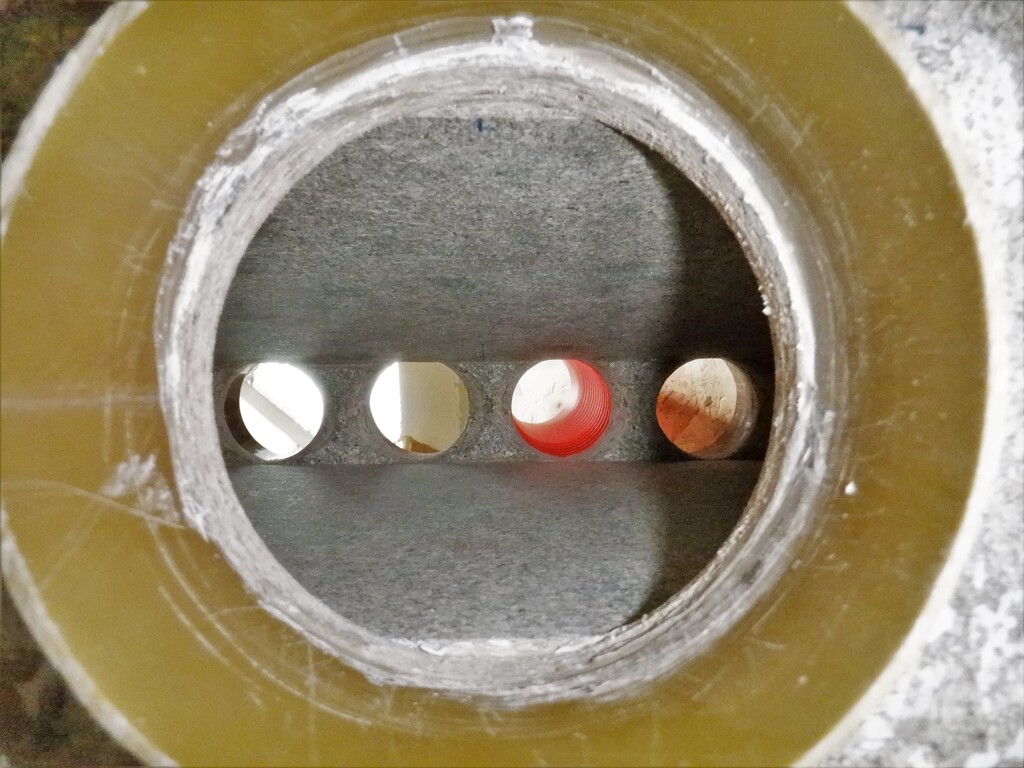
Then we connected up more water pipes, this time in 15mm diameter pipes that connects to our Energy Module (a buried tank of water), a pair of them so we can exchange the energy (hot water) from the tank to the Utility room and back again. the pair goes into conduits that were fitted to provide a “high” and “low” extracting points so we can draw off the floating hot water and put in new hot water down in the bottom of the tank. These 15mm pipes are only intermittently used so they don’t need a great deal of insulation, just the normal floor insulation to keep it warm while it is being transferred to and from the Utility room. The other 15mm pipe going into the Utility room is a connection to our Swimming lane. We did an external connection (drilling through the concrete wall) several months ago and so we laid in this pipe too. This Swimming lane connection will provide a source of cold water to help “sink” any excess heat away. The Swimming lane is a 25,000 litres of reasonably cold water to make use of!
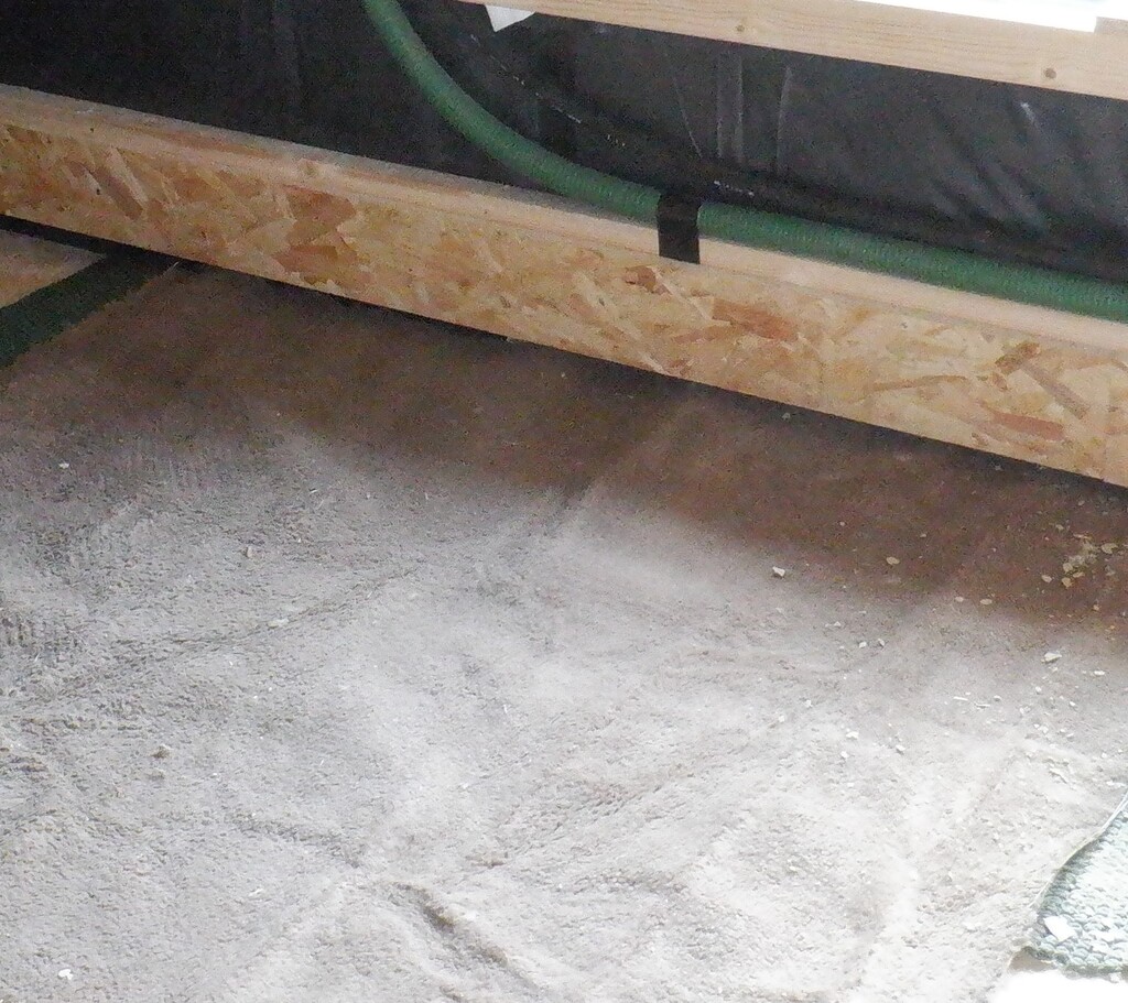
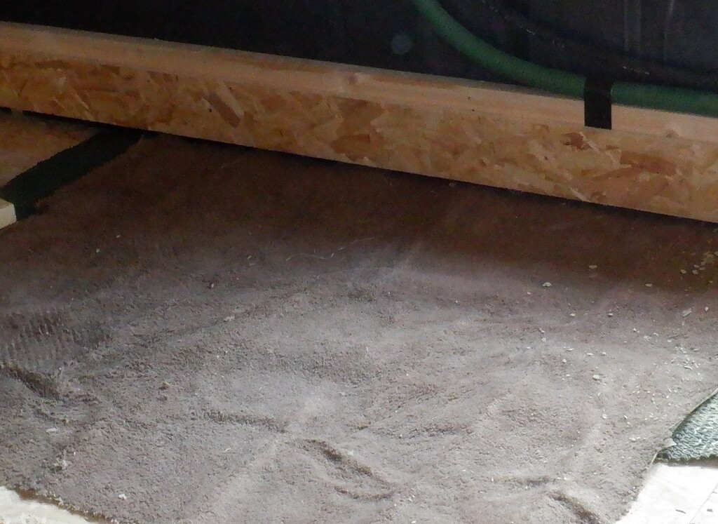
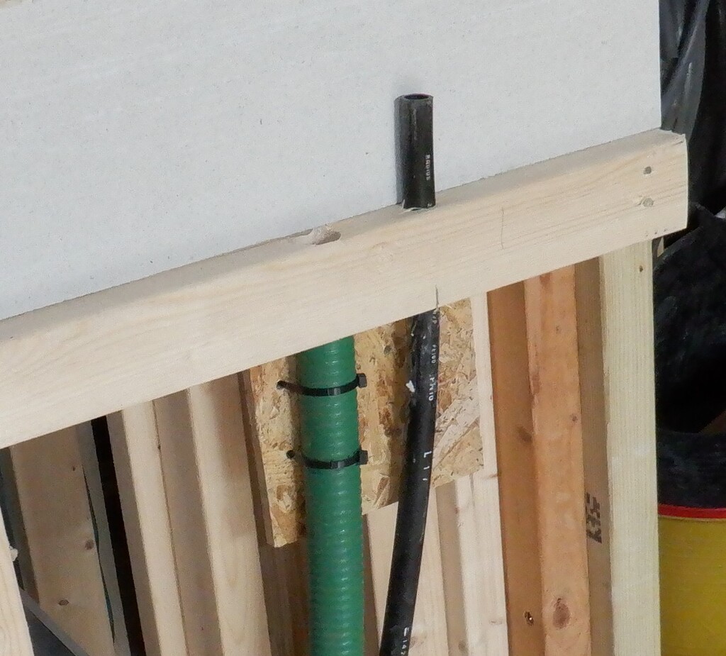
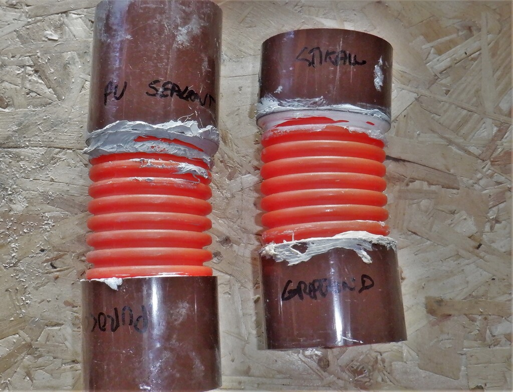
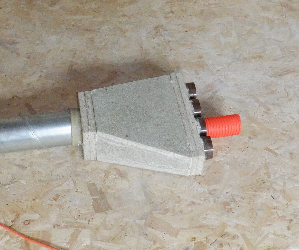
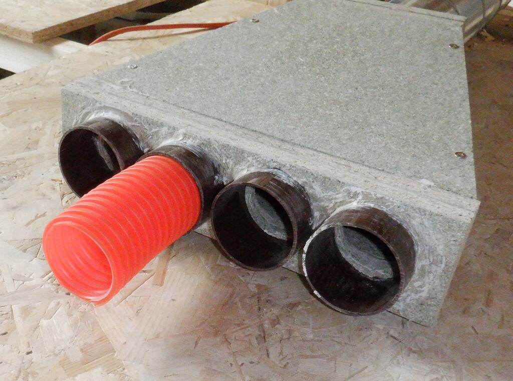
The final 15mm water pipe is also an external connection but this time, it is a low-volume irrigation watering system to serve the garden in and around the this end of the house and this 15mm pipe only needs to travel to our servicing chamber we have already made. At this point, a computer controlled water valve will be installed and connected to our cold water supply later on when we have designed and built such devices. The other connections to our servicing chamber are empty conduits, the first two being also irrigating watering feeds but this time up to the Eves for any hanging baskets etc. The final five other conduits snaking across the room are the temperature probes that will monitor the regions immediately surrounding our buried Energy module. All these conduits are 20mm diameter black polyethene pipes and we joined them to the sticking (out of the concrete) up portions using short length of the fatter 25mm polyethene pipe which fits perfectly and very tightly providing a smooth joint and transition for our cables and sensors when we push them down the conduits.
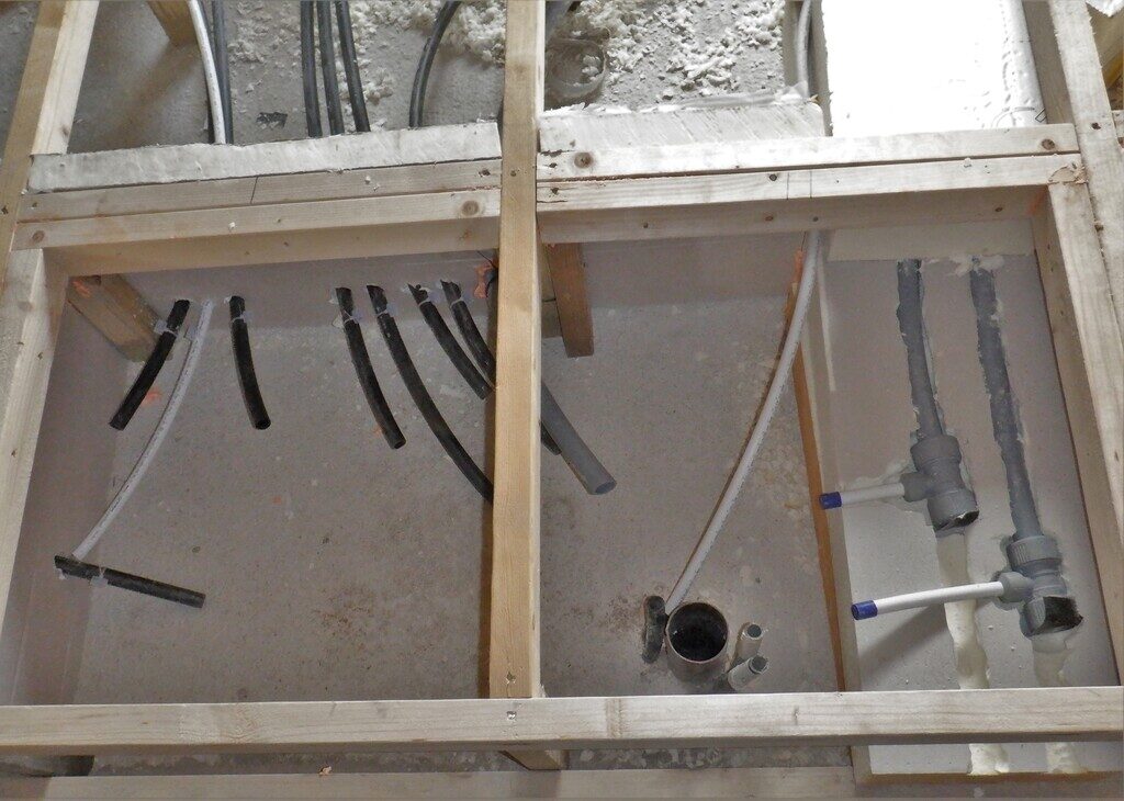
Bedroom3-Plumbing-access-area
Bedroom-3-Conduits-in-floor
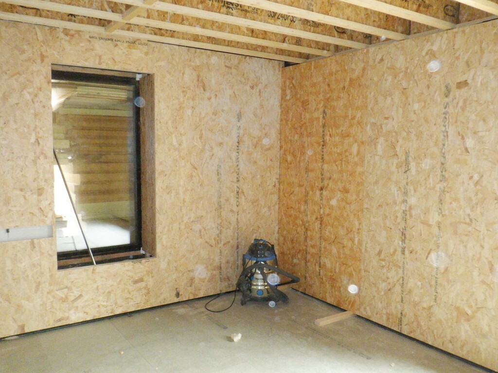
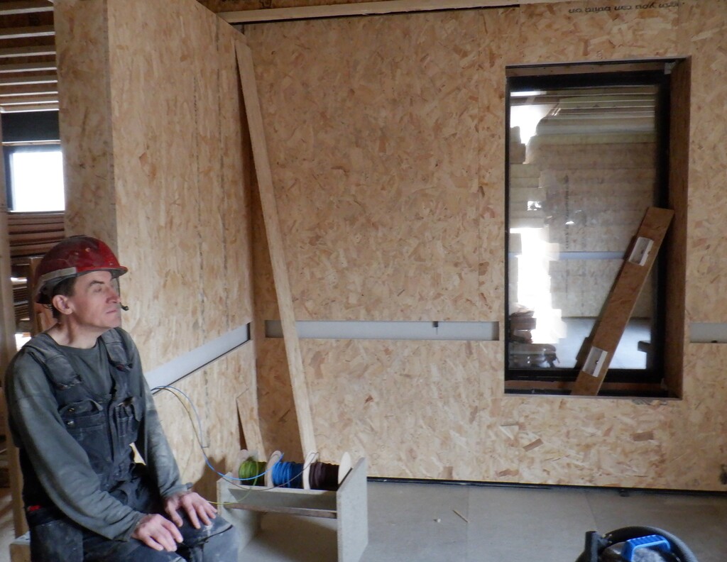
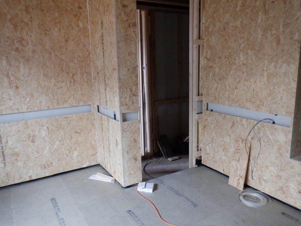
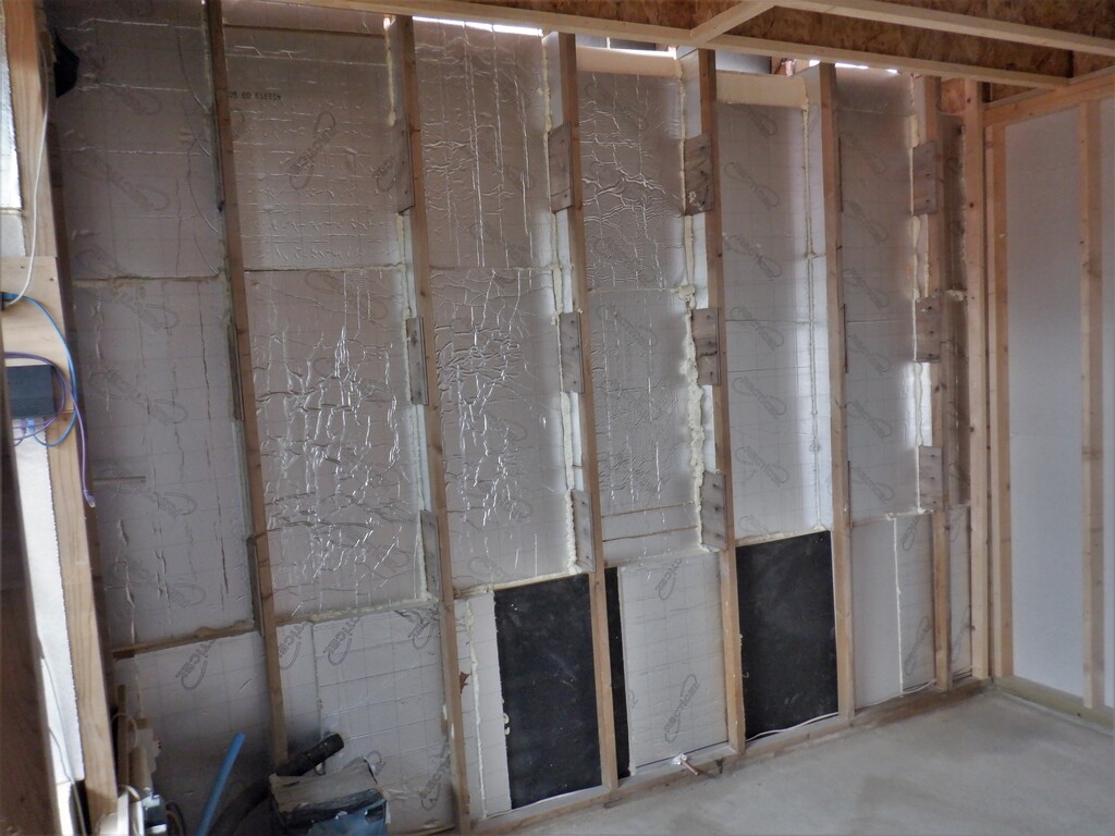
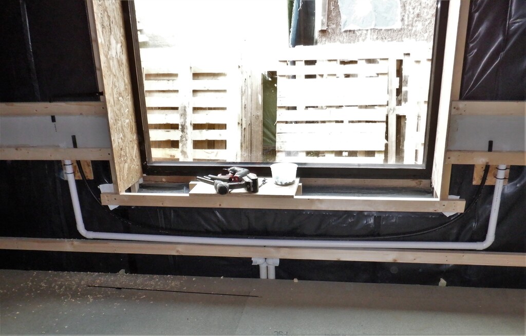
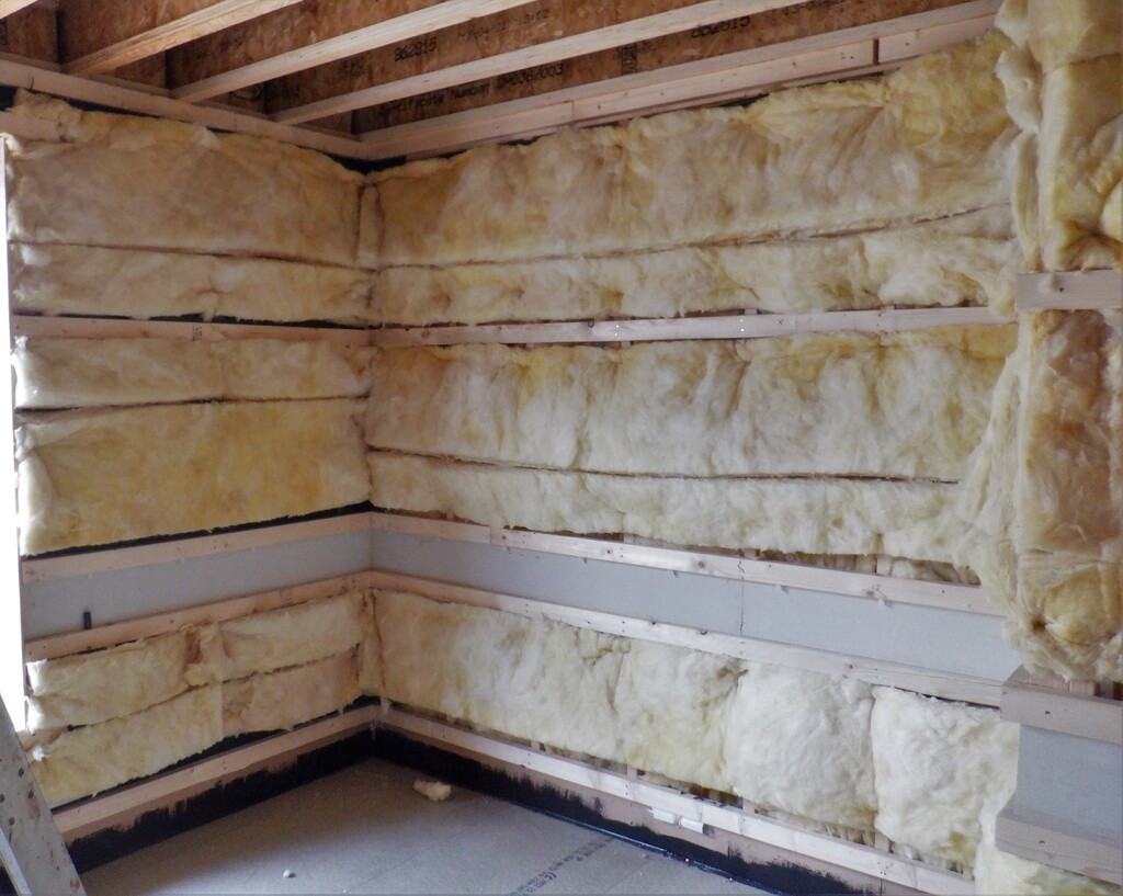
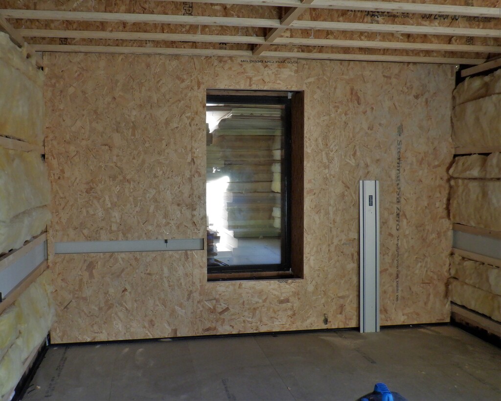
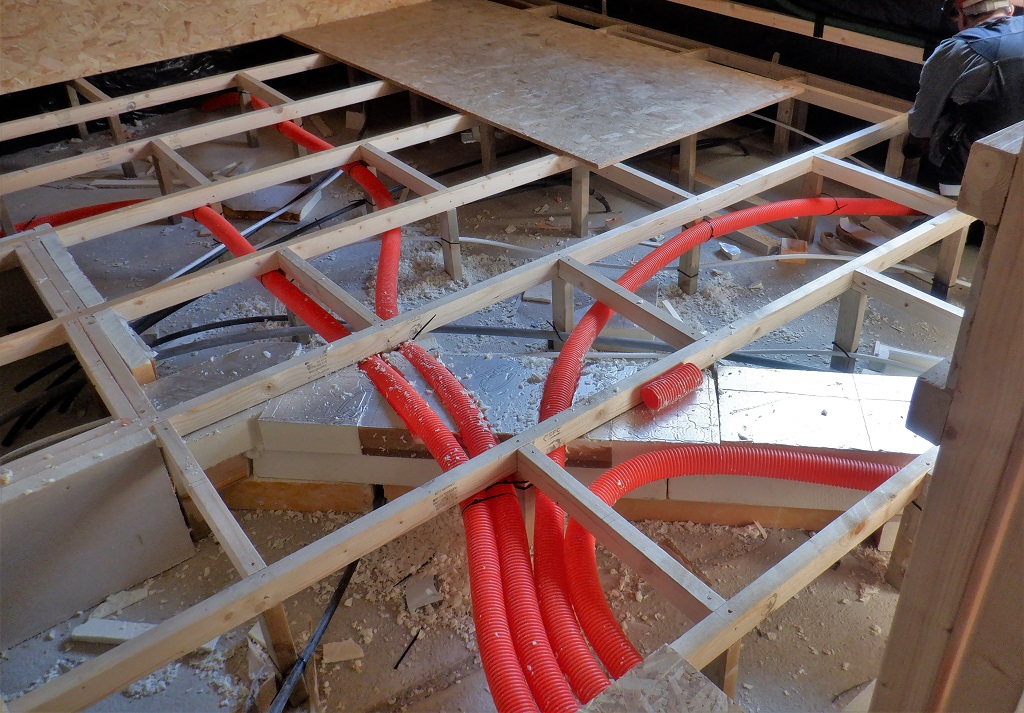
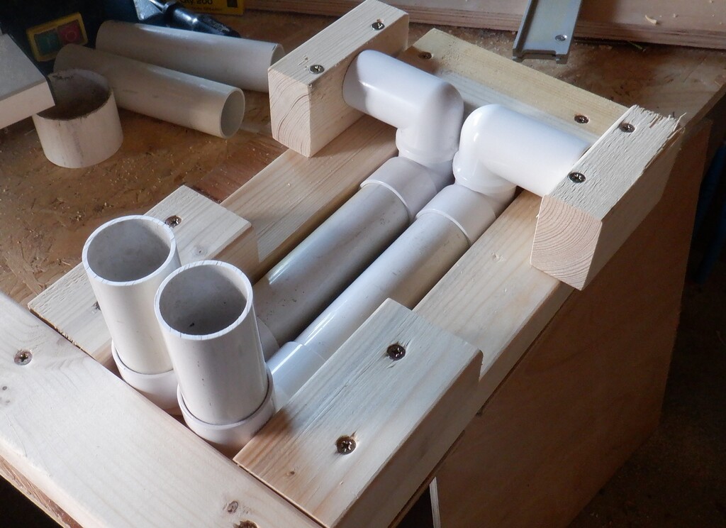
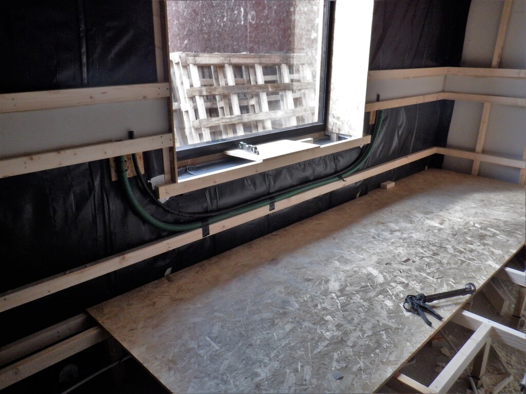
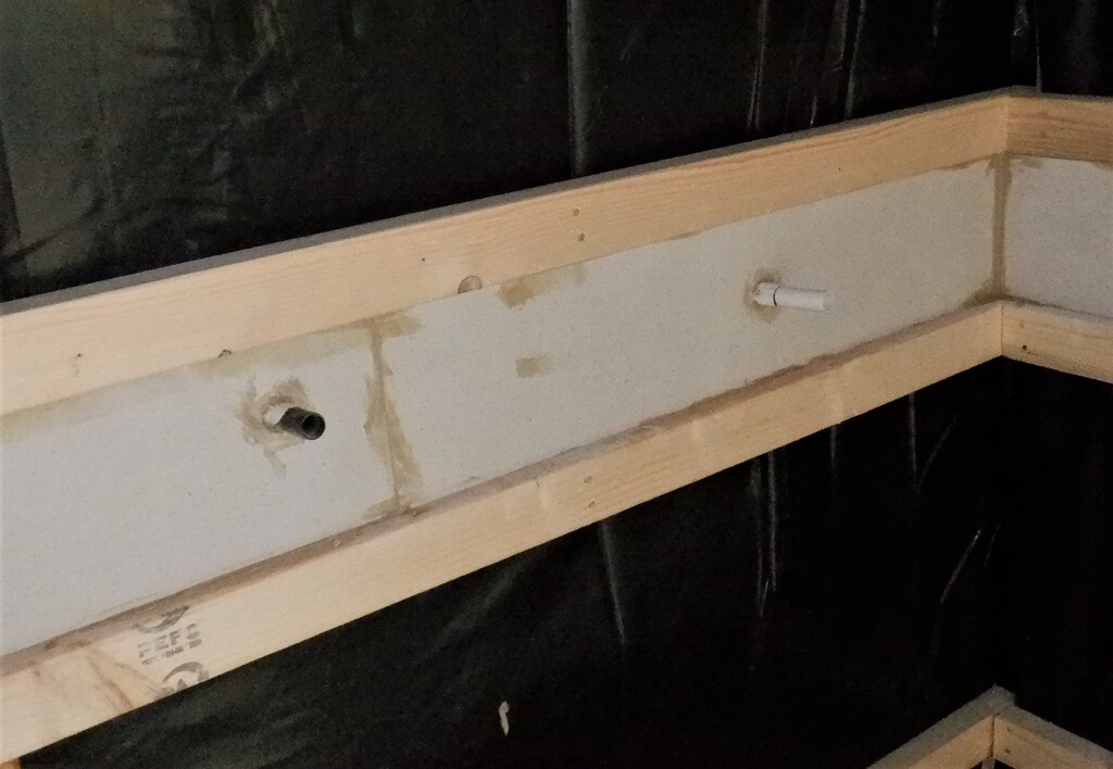
We are not quite ready to put on the lid or fill the space with the insulation rubbish because we got other tubes to lay in the floor, this time for the air supply. We are going to have four 50mm conduits running from the hallway, next to the doorway, and branching out to the four walls, to distribute the fresh air. We will have a air channel just at the bottom of the walls to spread the air out and enter into the room itself in a gentle flow, without too much disturbance to the feel of the room. We won’t be able to totally avoid any movement as it is meant to be providing fresh air and drawing the old stale air out at the ceiling, just like as if the windows are open on a warm day. Another set of conduits are needed to be laid in, this time to route the electricity cables from one side of the utility channel to the other side, going around doorways and windows. This will be done when our delivery of new twin wall plastic tubing arrives next week.
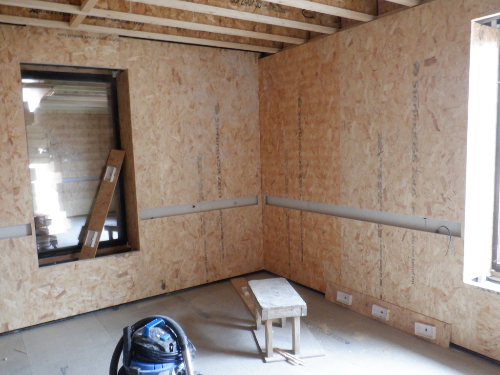
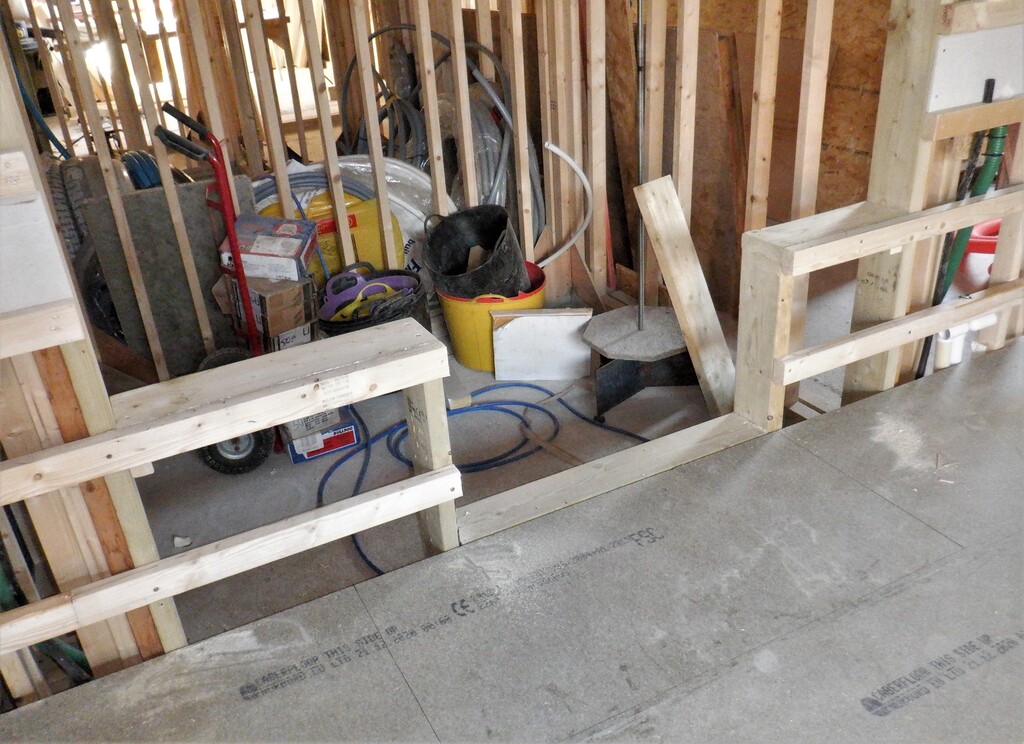
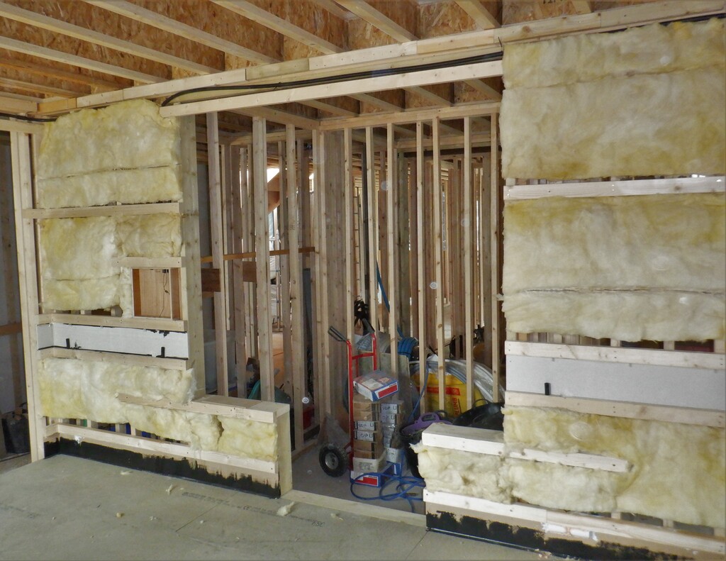
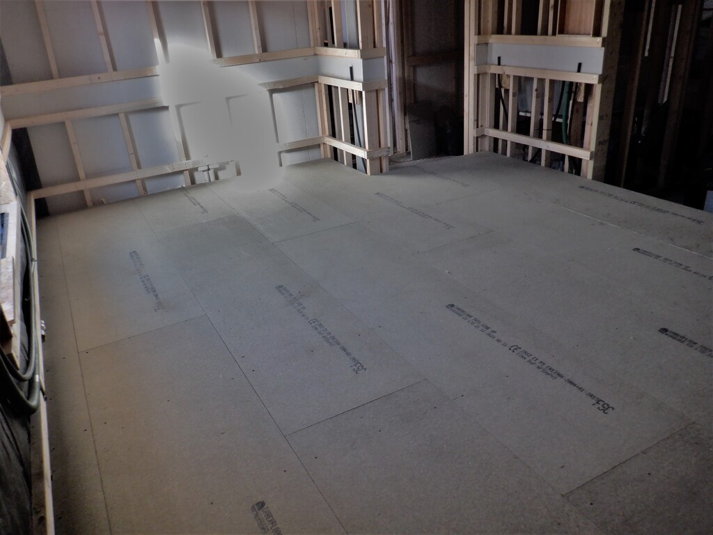
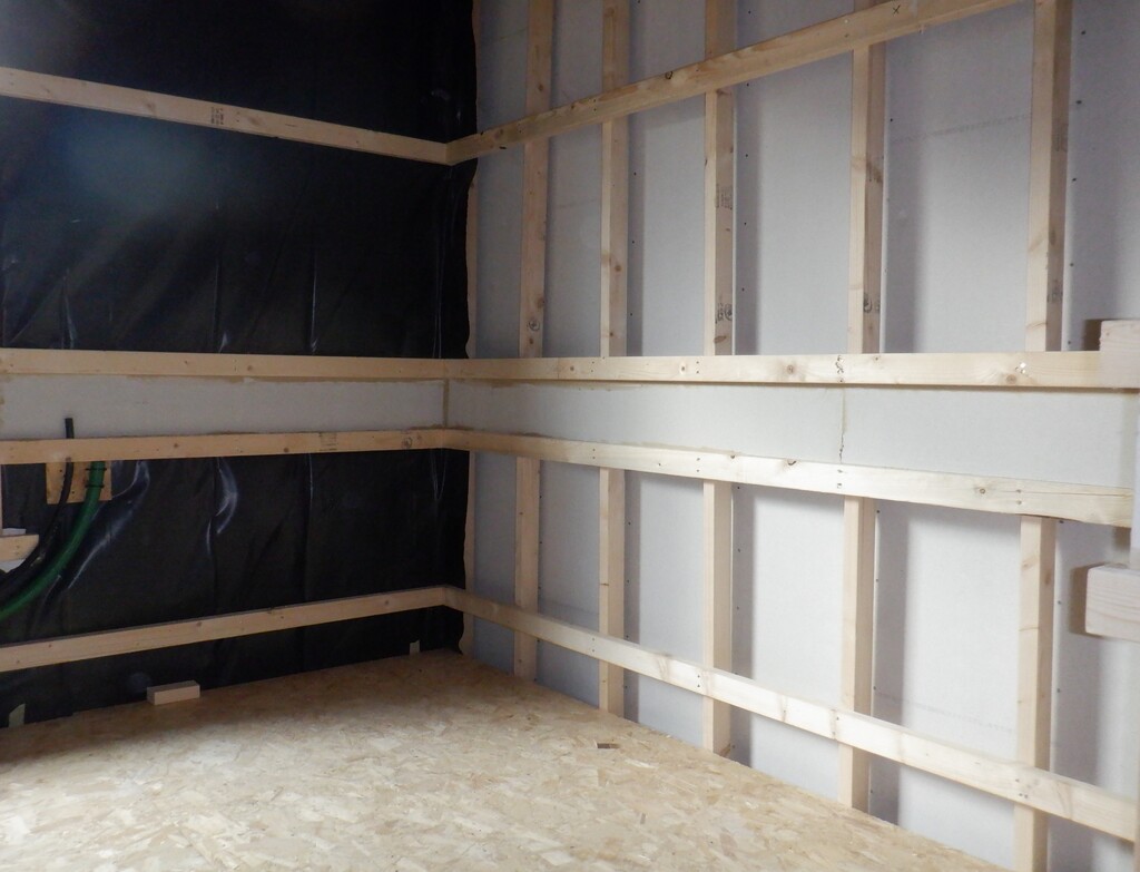
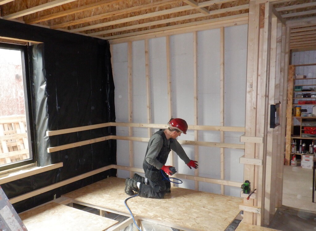
In the meantime, we started on the task of nailing up the horizontal wooden rails, we called these utility rails because their function in life is to provide the space for our Utility Channel that goes around the whole room at the 800mm to 900mm height, plus also we are using this separation to allow for the air channel to run around the room too, down near the floor. Each of these horizontal CLS rails (our usual 63mm by 38mm timber) are positioned as follows:
- 235mm off the floor (air channel)
- 772mm (bottom boundary of utility channel)
- 1010mm (top boundary of utility channel)
- 1703mm (mid support point for wall board)
- 2422mm (support of wall boards at top of wall)
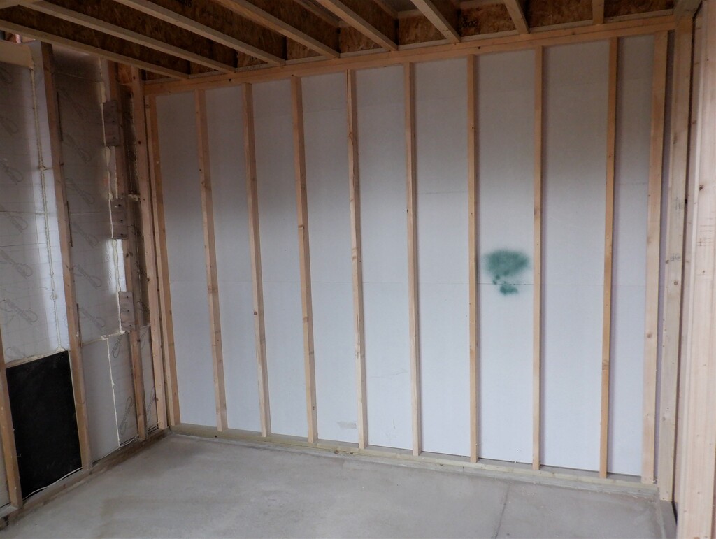
These measurements are for the top edge of the CLS timber because we can see it with our green laser light (more later on) and a 22mm offset is also added because we are measuring from the floorboard supporting framework that will have the 22mm thick floorboards laid down later on. We marked the door post with these measurements and then clamp our green laser line generator which is sitting on a small shelf at each measured mark. Then we went around nailing up lots of CLS timber to create the wall framework for holding up the finishing surfaces and of course to provide the space for our electrical sockets etc.
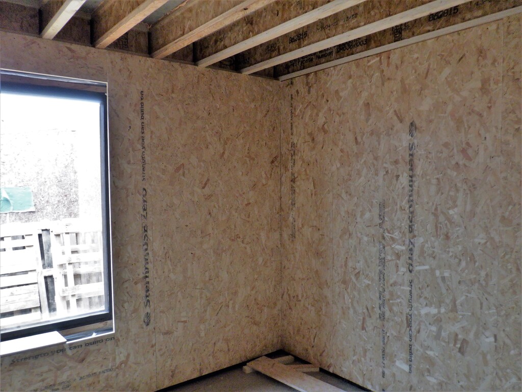
We started using our left-over timber (a large pile of it in the kitchen) to form these horizontal rails by using a biscuit joint to join smaller lengths together. We also inserted a horizontal rail at the window seat level, this one being 500mm off the floor surface.
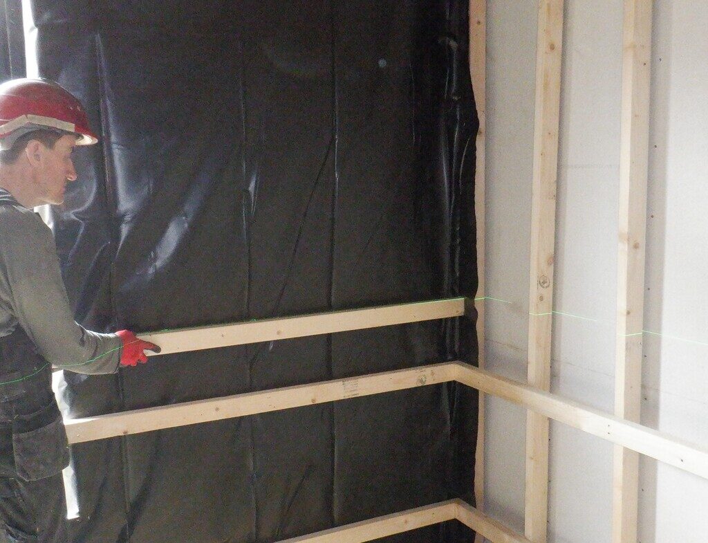
Aligning-a-rail-to-the-laser
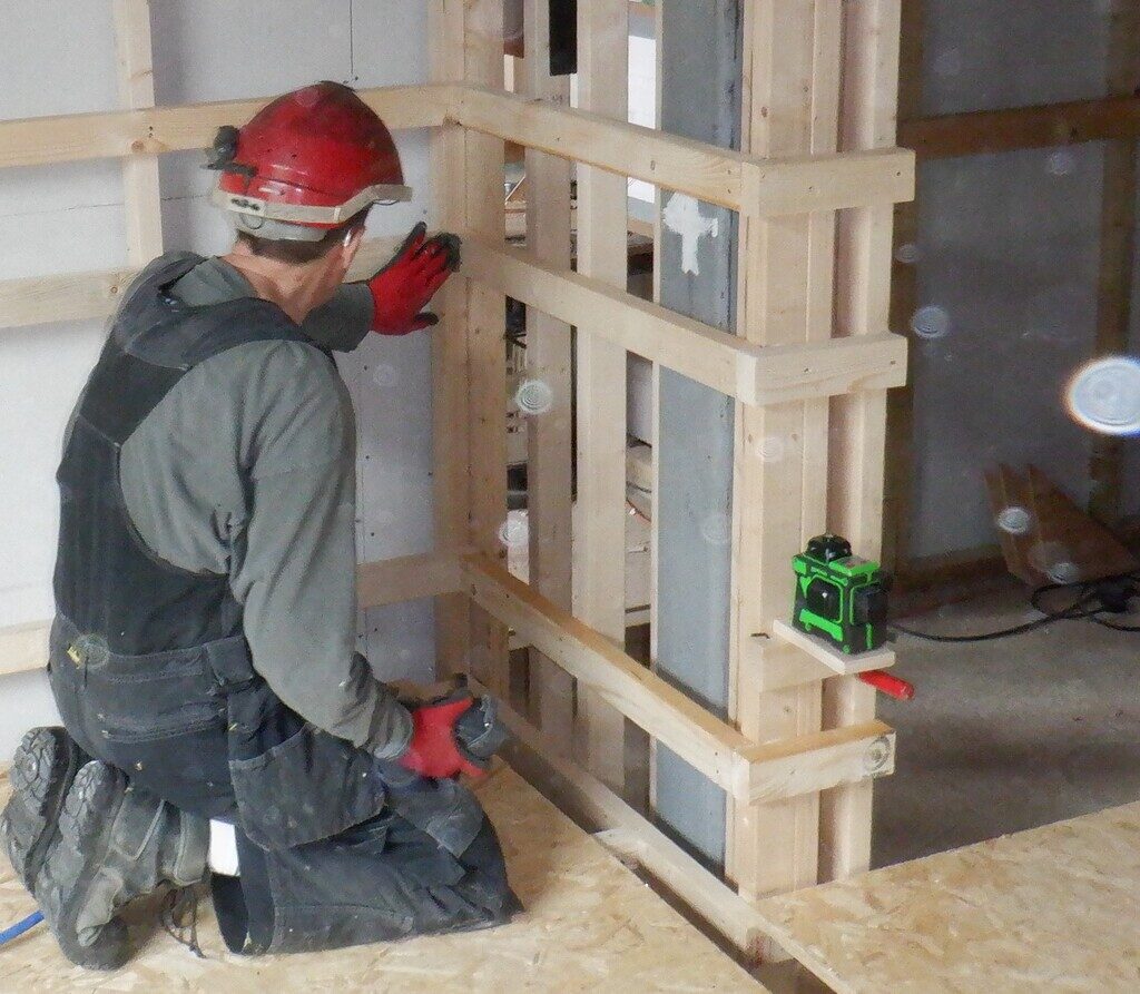
The-laser-bracket-clamped-to-the-wall

First-three-rails-fixed
That concludes the work so far for this week and we will carry on next week with the wall support and laying in more conduits when they arrive.