Continuing with Bedroom 3, this week we installed more various elements into the wall and floor structure to provide additional functionality to the operation within the room like, for example, a control box that will contain the electronic controller, a display module and local circuit breakers for the power lines. This was constructed from sheet of left-over 12mm thick plywood board material and made two open faced boxes, measuring 360mm wide, 75mm deep and 400mm high.
We designed it this way to allow the shell to be fitted into the wall structure but not too deep to intrude into another mechanism like the sliding door modules. These boxes will be covered up by the wall boards, the 18mm OSB sheets later on but will have internal brackets and fuse holders plus a display unit with built-in audio amplifiers to help drive the four speakers that will be the standard provision in this size of rooms.
The next task was to drill 20mm wide holes for more conduits to connect to this buried box and through the utility channel too and plus another one going up to the ceiling to serve the lighting circuits. Talking about conduits, we installed a couple of extra ones either side of the entrance to the room, these being 20mm diameter pipes, to help thread the mains AC power lines in and around the utility channel. At this point, we have still the problem of having a flexible conduit that also needs to go either side of the entrance, this time to supply bunches of network cables, speaker wires and other low voltage signalling cables. Our supplier of the 40mm wide twin-walled conduits still have not arrived so we have been looking around for alternatives. It looks like that we will have to use rigid plastic plumbing pipework, the 32mm diameter size that is usually used for waste water plumbing but we could use that, coupled with sweep bends and achieve the method of channelling the cabling around our windows but we would still need a flexible solution and the nearest type we can find is a corrugated water hose being sold in 10metres length and 32mm internal diameter and this would be used at the entrances and going around en-suites etc. We will place an order for those solutions soon.
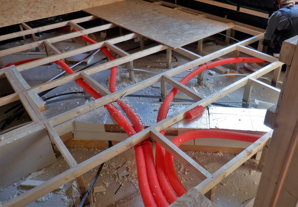
In the meantime, we started looking at our air distribution system, the four separate orange 63mm ducting that will take the air to all edges of the room. We mounted our air splitter chamber in the entrance way so it is ready to be connected to the main air duct when that is constructed, and the four outputs were then connected to lengths of the orange 63mm twin-walled conduit. These conduits travelled across the room, cutting paths through the rigid foam board that covers the hot water pipes and anchored to various floorboard support legs and arrived in approximately the middle of each wall.
Distributing-air-around-the-room
Next was to design an sweeping adaptor that will take the output of this orange ducting and split the air into two sideway facing wings to send the fresh air along just behind the wall boards. We had thought that we could design a model on the computer and generate the object using our 3D printer but it turned out to be quite a complex shape sweeping up, backwards and then forward and sideways, all because the air duct is underneath the floorboard, has to go around the back of the support framework and arrive above the floorboard level but hidden behind the wall board. There were seven individual parts to make it possible to generate each 3D part on the printer (because of the limitations of building up the plastic object layer by layer so it is very very difficult to create hollows or bridges without it collapsing or having internal support structs etc.) and it would take well over 24 hours to just print one of these winged adaptors.
3D-diffuser-feed
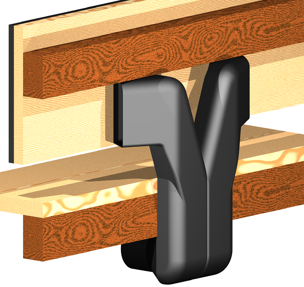
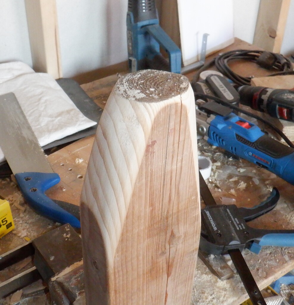
We needed lots of them all over the house, at least fifty of them! So an alternative solution was needed and it found it by using the waste water rigid plumbing pipes, the solvent weld types, not the push fit ones. We took a series of 90degree bends with short straight pieces and created a fair substitute design that does the same job of channelling the air out and sideways behind the walls and into the room. We sliced little bits off various parts to reduce the size, trying to make it as compact as possible and eventually we applied the solvent and glued it together. It is a twin pipes going up and then turned to form the two outward facing wings. Finally, we took short lengths of the rigid 68mm brown pipework and experimented in heating it up with the hot-air gun and using various shaped wooden moulds, we could stretch the plastic out and then squeeze it down to wrap around the two 40mm pipes of our adaptor.
Pipe-flaring-tool
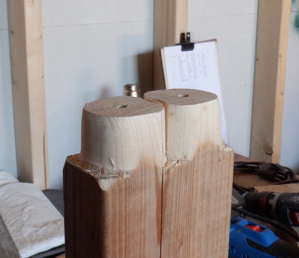
Pipe-shaping-tool-inner
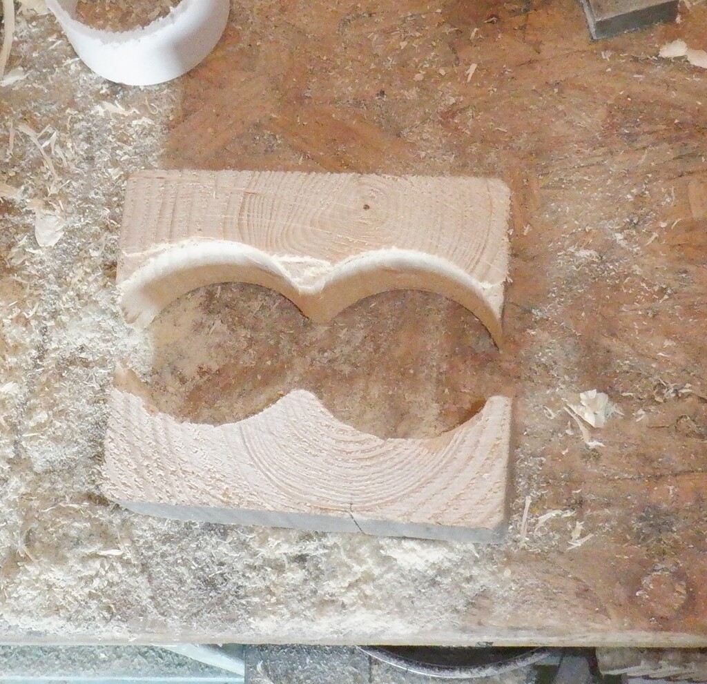
Pipe-shaping-tool-outer
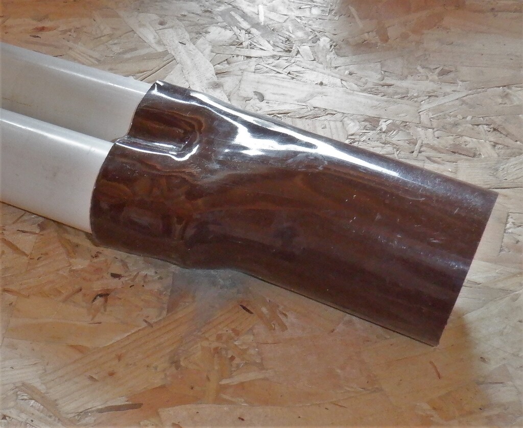
Shaped-Splitter-pipe-
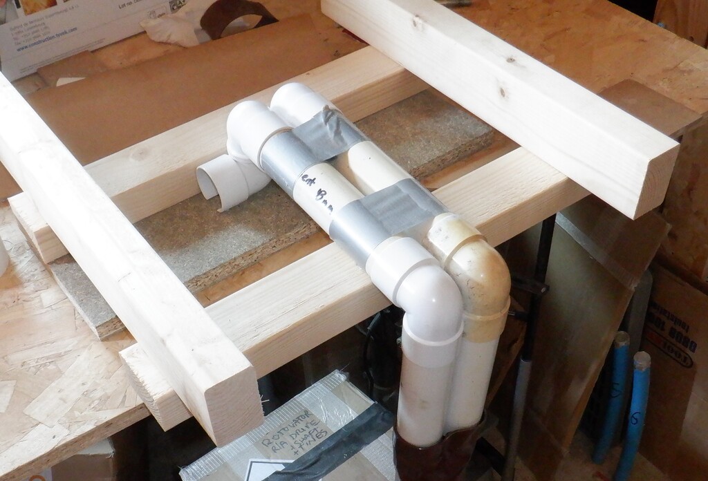
Protoype-air-diffuser
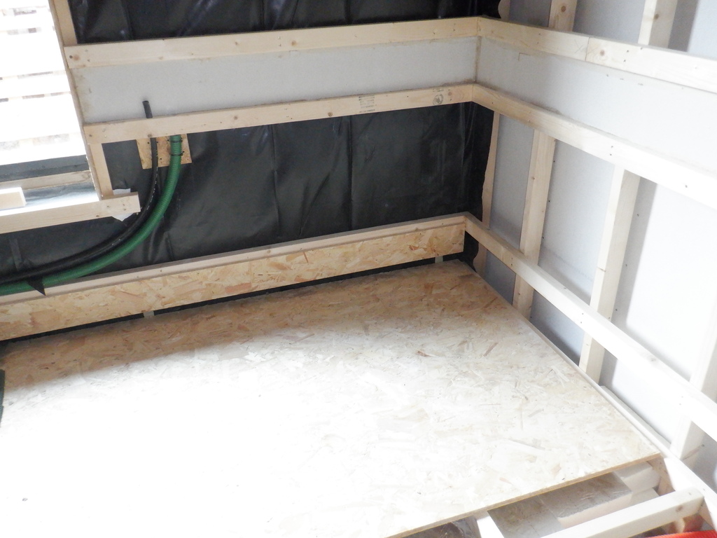
We then did a test run by fitting it into the wall, underneath the large window in the room, placed two strips of the MDF strips (with little cut away sections) and screwed it up to the wall legs. We found two narrow pieces of our 18mm OSB left-over pieces and also screwed them on the horizontal rails so we created our air channel hidden behind the wall board. We connected the orange ducting up to the new adaptor and connected our old 150mm centrifugal fan to the main air splitter chamber to give it a blast of air through the system. We could feel the air gently sweeping along behind the OSB strips and gently entering into the room itself. We wanted to make sure that the air would gently distribute fairly evenly along the whole wall and had thought that we may had to cover the air channel with a cloth barrier to help guide the air to spread out but it turned out to work just fine without any additional cloth barrier after all.
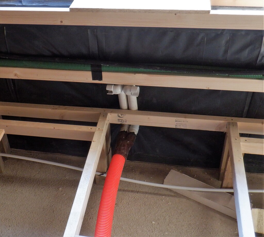
Prototype-in-place
Test-channel-at-base-of-wall
We then found some old pieces of underlay and carpet to place on the floor (just a sheet of 18mm OSB board that we are using to help us safely negotiate the floorboard support framework) and had a look at the finish results. The first implementation of the wall boards is positioned to allow a 50mm (a 2inch) air gap between the floorboards and the bottom of the wall board, to provide room for the air to escape and have our carpet fixed down in the gap. But we decided that 50mm was too big so we reduced the gap down by 12mm to just 38mm and looks much better. the air was still escaping out quite easily even with the carpet in place too.
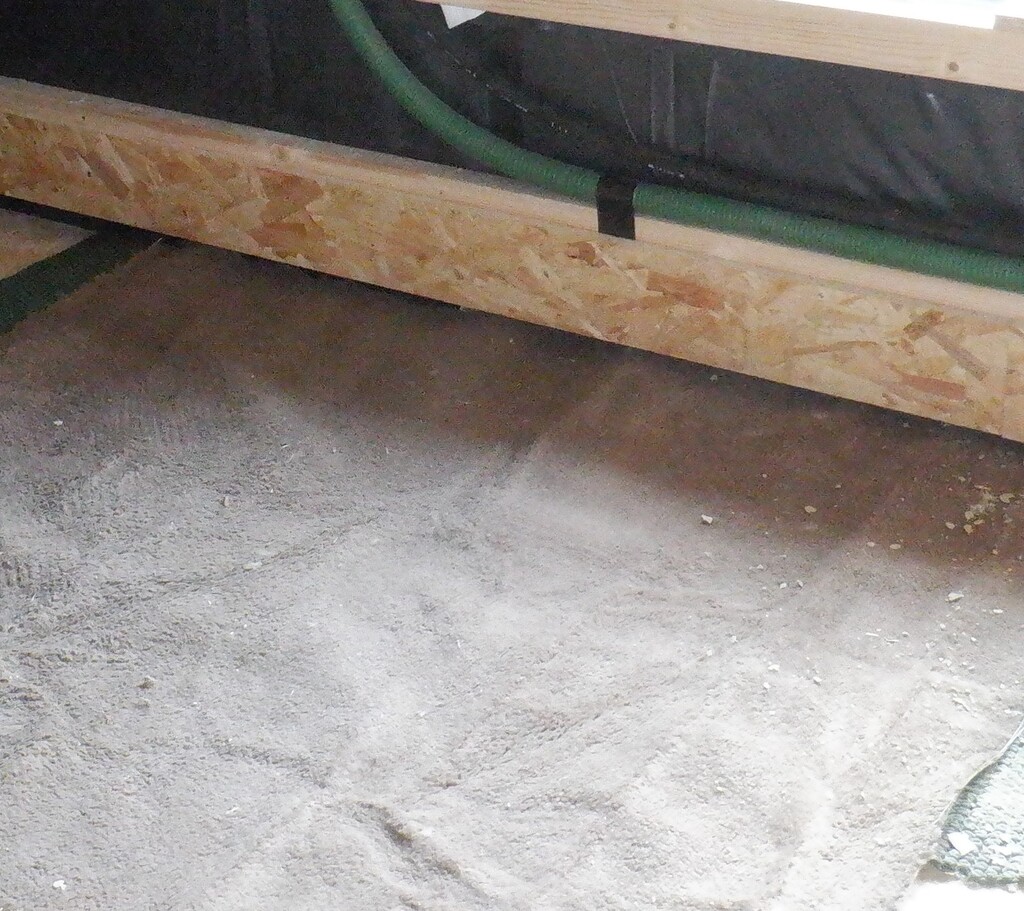
Carpet-under-50mm-gap
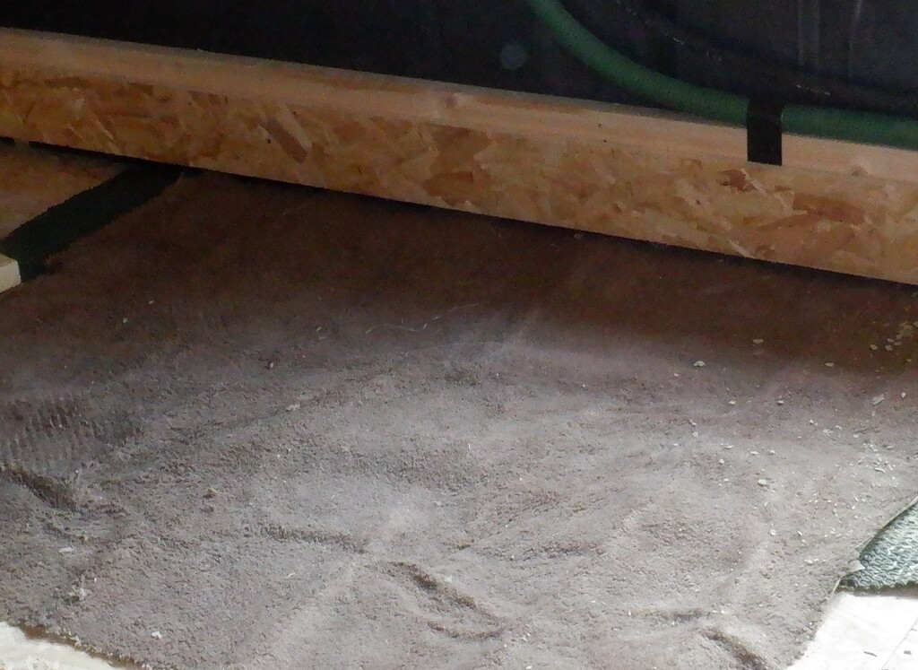
Carpet-under-38mm-gap
While we were doing our experiments, we ordered all the parts to make plenty more of these air divertors, some 450 pieces, a mixture of sweep 90degree bends and 90degree elbow bends plus also a pack of grey pipes too, all for overnight delivery. We made a jig to hold the parts whilst they were glued, This meant that we did proceed to make a further three adaptors and proceeded to install them into Bedroom 3, one under the smaller window, one along the section of wall just beyond the en-suite and the third one in the middle of the wall that is shared with the Utility room. We trimmed the orange ducting, applied sealant glue and therefore formed the ventilation system for the whole room.
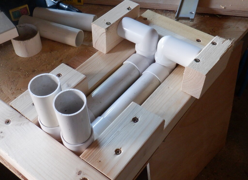
Final-air-diffuser-design
We also ordered 20 sheet of 6mm MDF board, paying a ridiculously high price for them (the world has gone mad for timber products!) and these will serve to provide the smooth backboard to the air channel. We will have to paint it black to reduce the gleam peeping out from under the wall edges.
Another change of an implementation design and strategy was the cold water pipe. We had used the 28mm white plastic pipework that is designed for domestic water, especially hot water because it has a metallic barrier moulded into its wall thickness to prevent dissolved gases from “upsetting” the plastic material and forming weakness after a decade or so. But this kind of pipe is rather expensive and we need lots of it to provide our hot water circulation system. So we decided to swop out the 28mm cold water feed and replace it with 32mm polyethene water pipe instead. The pipe is much cheaper and even the T-junction adaptors are half price too so now we have a blue coloured pipe running from the Utility room and reaches the access chamber where we will have all our connections done to serve the en-suite basin, cistern and shower.
Once we have doubled checked that everything is laid out, all the conduits, pipework and air ducts are in place under the floor, then we brought in loads of the shredded chopped up pieces of our left-over PU foam board and filled up the void and empty space in among the legs and pipework. We moved about two thirds of the content of our giant bag we got outside and filled the space to the level of the floor joist.
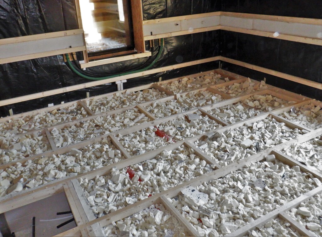
Filling-the-undefloor-with-Scrap-insulation-1
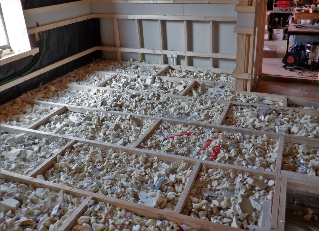
Filling-the-undefloor-with-Scrap-insulation-2
The last day, the Friday, we tackled the task of laying down the proper set of the 22mm thick tongue and groove floorboards. This chipboard material was laid in the long direction, starting at the en-suite side of the room, slicing off the tongue so that the full thickness is fully on the framework around the edge of the room. We also sliced off the tongue at the beginning at where the entrance is so that would be ready to butt up when the hallway own floor is constructed. We put down three rows to see how it came together and everything looks good so we lifted those pieces up (they weren’t screwed down) and put in the finishing layer of glass wool to fill the final void directly under the floorboards to help deaden the sounds as much as we can do. The chipboard pieces were then placed back into place and this time, screws, three of them in each joist and also more around the edge of the room too. We put down 6 rows plus a little narrow strip to finish over by the large window. It was tricky to get the ends of each row in as the tongue needed to be inserted into the previous board’s groove but also to move pass the lowest horizontal rail on the wall too. This was especially true for the last narrow strip and we had to rasp a clearance slot where the wall posts were, just in order to get the tongue to engage fully into the groove. But we got there!
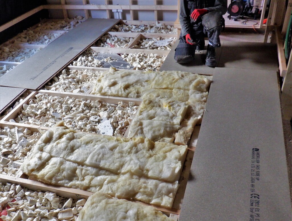
Then-topping-with-100mm-glasswoool
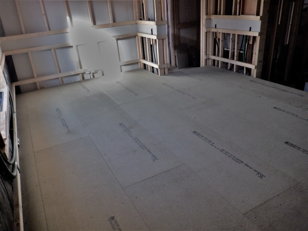
Bedroom-3-Floor-finished-1
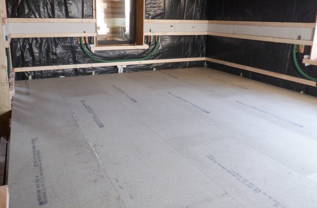
Bedroom-3-Floor-finished-2
That sees the flooring all completed now so we can now look forward to be doing the walls next. It is nice to see a room taking shape.
Leave a Reply
You must be logged in to post a comment.