Category: Great Room

The Great Room with Gallery and spiral staricase

  • Moved 2tons of Fermacell Boards to House

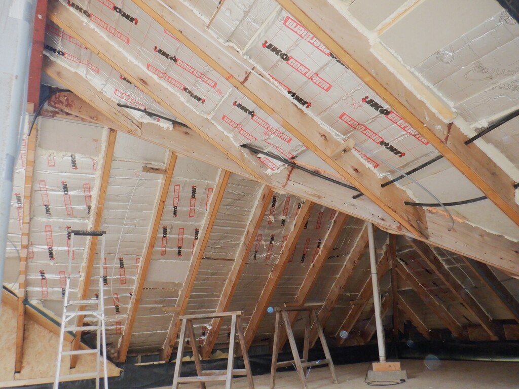
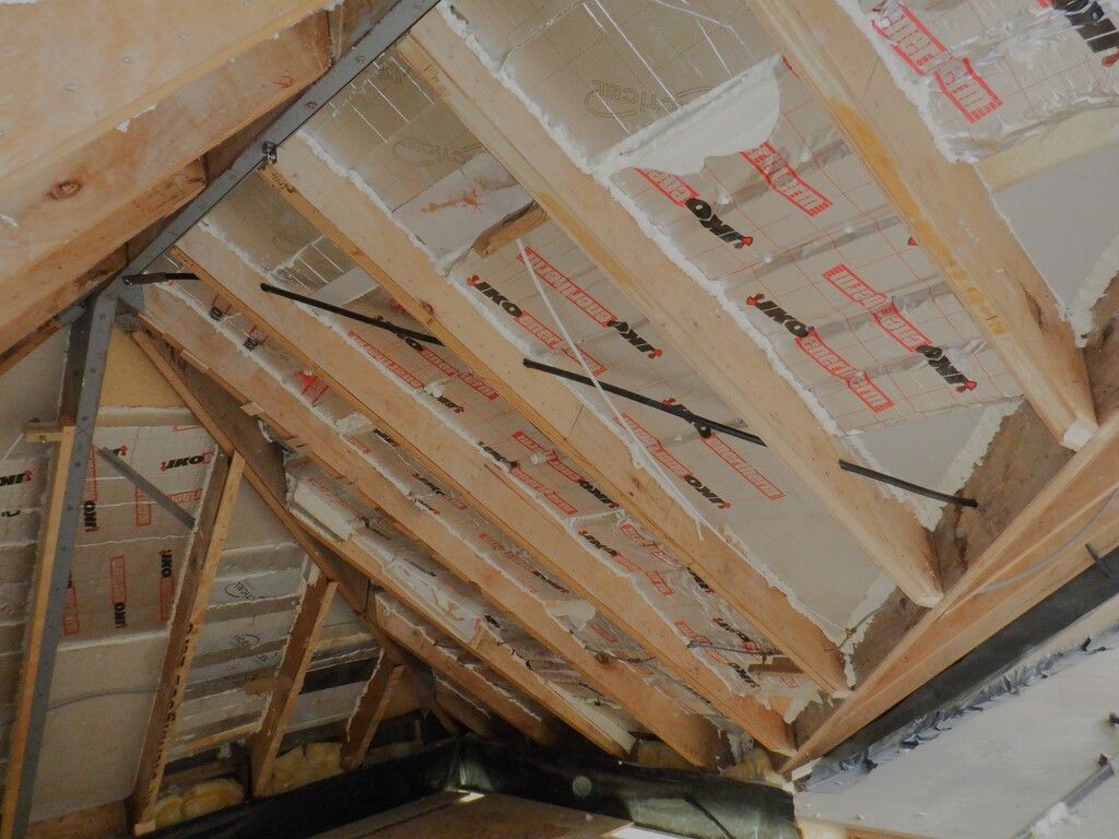
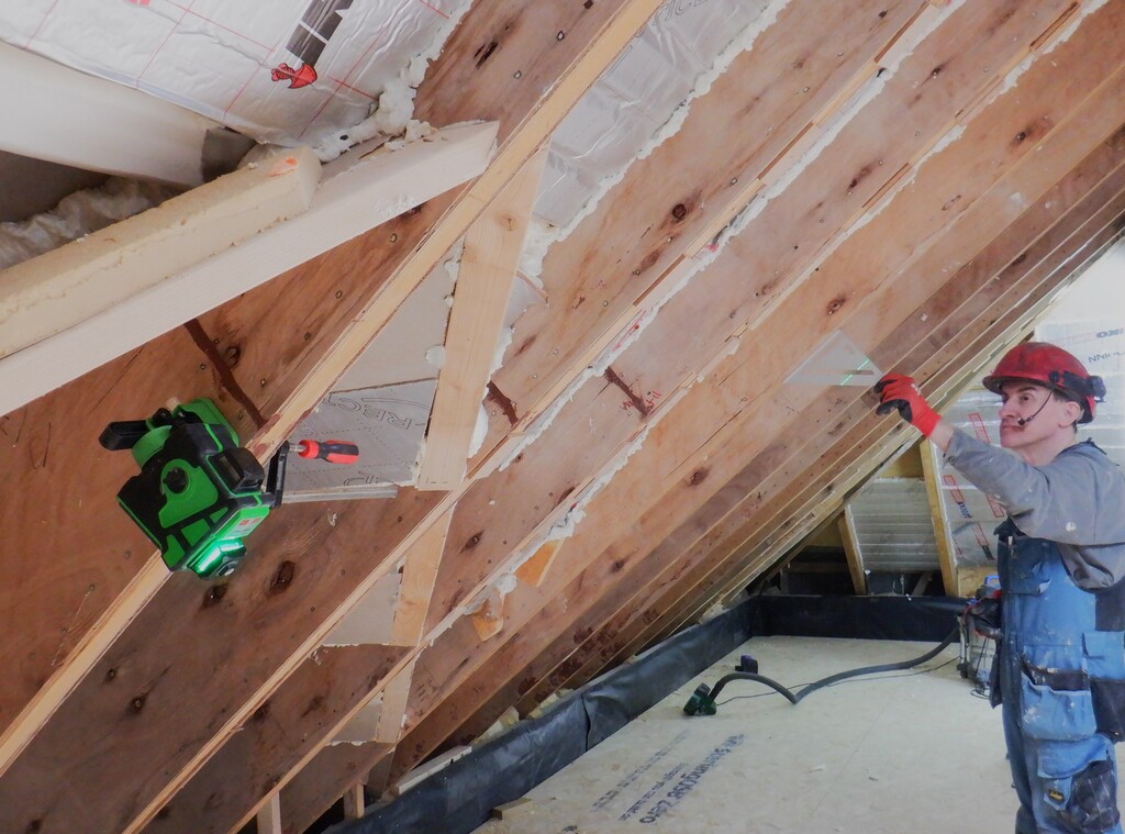
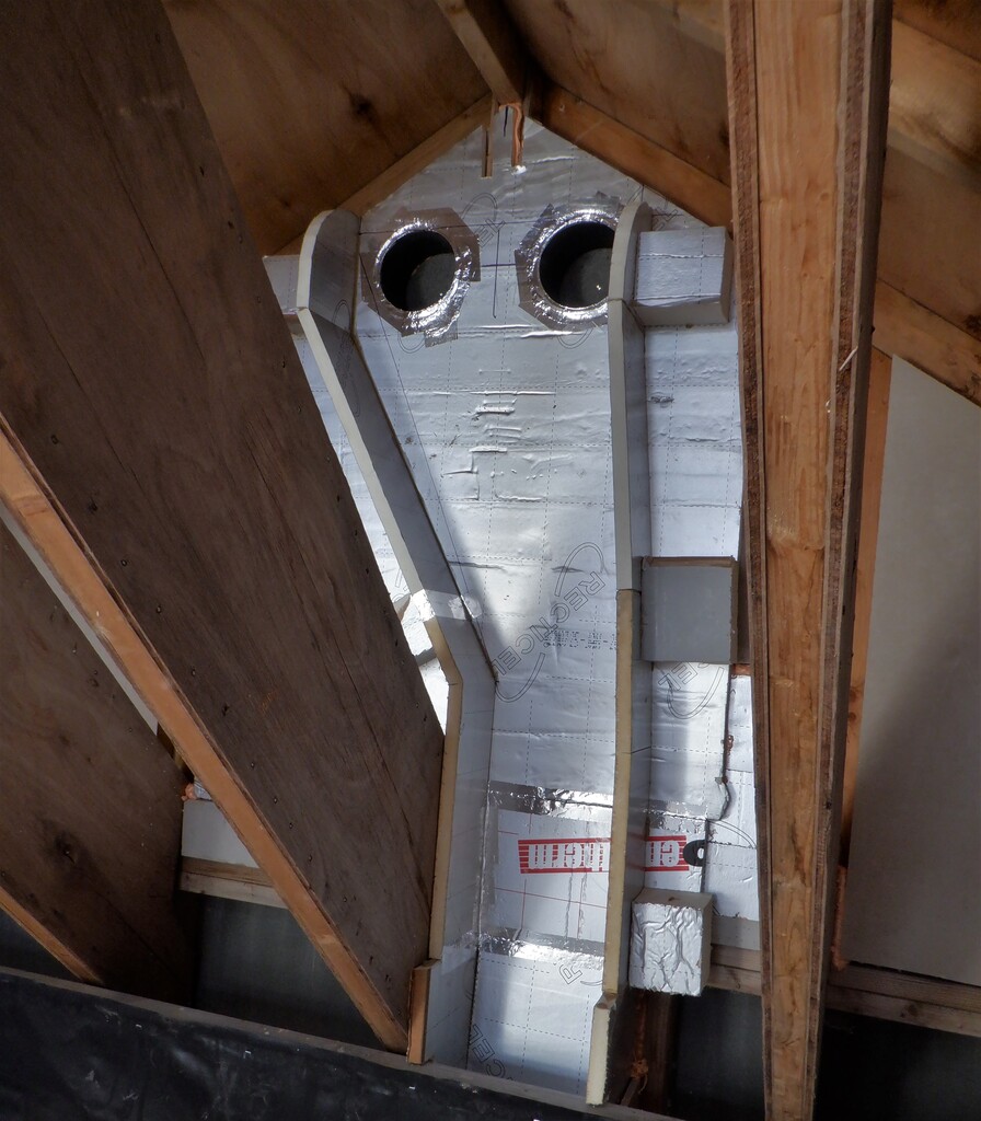
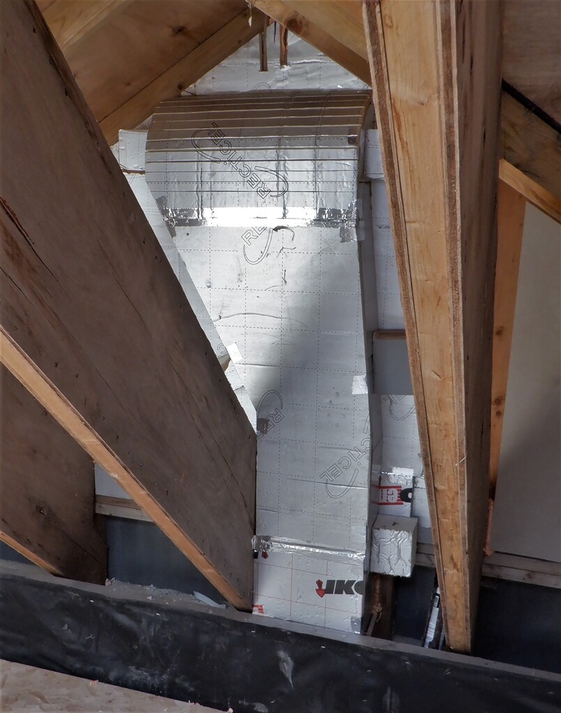
    This morning, while catching a spell of dry and sunny weather, we decided to move in some of our plasterboard like material which is called Fermacell. We are reaching a point where we need to start fixing the final finishing layer all over the “ceiling” in our Great Room so here was the Opportunity.
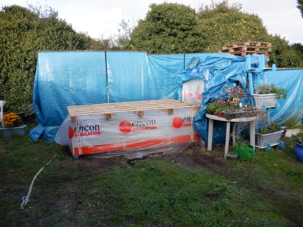
    Each fermacell sheet measures 2400mm by 1200mm and 10mm thick and every separate sheet weighs 35kg each! We got our large flatbed trolley, pumped up all the tyres, put on some 11mm left-over pieces of OSB to protect the clean fermacell sheets from any dirt and dampness and rolled up to our stack of pallets we got stored outside under lots and lots of tarpaulin.
    We uncovered the front stack which revealed that we have two pallets sitting there, each one having sixty sheets so that was our target. The label says that these sheets were manufactured in February 2022 and that a pallet weighs 2.1tons!!
    It was satisfying that there were many layers of protective plastic covering each pallets, even a heat-shrunk layer as well. So the fermacell was nice and dry.
    So we offloaded 20 sheets, weighing “only” 700kg, thinking that the trolley can take it. we push and pulled the trolley but were struggling to roll it all the way to the front door of our house. It was at this point that we noticed one of the tyres was completely flat!! No wonder it was hard work!!
    (no photo because we didn’t think of it!)
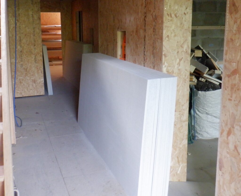
    So we proceeded to unload these sheets stand them upright, leaning against sections of our hallways downstairs. We put some outside our Linen cupboard and also on the opposite wall across the Bathroom doorway as well.
    This freed up the trolley so the next hour was spent repaired the tyre and putting in a new “old” inner tube. We think that the hole where the valve comes through the metal rim of the wheel is the cause of the damage to the inner tube. We cleaned up the hole and put on extra layers of protective rubber patches around the valve and got back a working tyre again. Don’t know how long it will last but long enough for doing this job today!!
    For the rest of moving the sheets, we went back and forth twice more with thirteen sheets and the last run had fourteen sheets. We unloaded them and built up a third pile alongside the Entertainment Room.
    Fermacell stacked downstairs

    Fermacell stacked downstairs


    We rewrapped the remaining pallets, leaving behind the wooden pallet to help protect the rest and pulled our tarpaulin back over again, putting back the OSB sheet on top of the plastic, to stop claws from birds from punching holes!
    Empty Pallete

    Empty Pallete


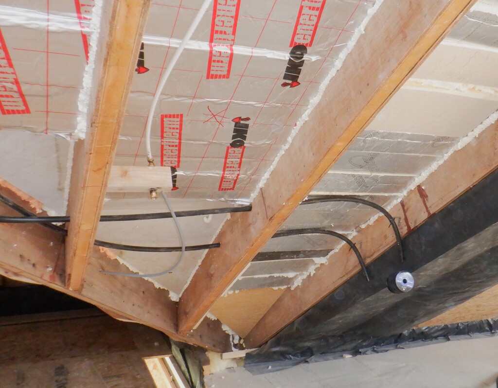
    These sixty sheets will go a long way to cover the ceiling, plus also a lot of the walls in our Great Room so that will keep us busy for a while!
  • Great Room Ceiling Finally Filled and Covered

    Over the last two weeks, we have been getting on in finishing off filling the roof rafters up in our Great Room. It is a simple case of inserting a mixture of 150mm and 200mm thick glass wool to finish filling up the space in the rafters, in front of the hard PU insulation. Some of them were well filled so we could only get the 150mm thick wool in, but most of it had the 200mm put in. One thing to remember about these glass wool these days, the label says 200mm thick but even after leaving it unrolled and laid out flat for more than a day, it only expands to 150mm thick. We just can’t see how these manufacturers can claim that it will expand to the full thickness as stated on the labels. So we have learnt over the last year or so, to automatically downgrade the thickness and work with that.

    Anyway, we went around all the rafters we got left to do in the Great Room, and then proceeded to cover it up with our usual black plastic vapour barrier.

    Last of the plastic lining 1

    Last of the plastic lining 1

    Last of the plastic lining 2

    Last of the plastic lining 2

    Last of the plastic lining 3

    Last of the plastic lining 3


    Then this week, we protected this plastic layer with our 11mm OSB boards. We had 42 sheets left in our stock and we ended up with four sheets left-over. Not bad guess for ordering hundreds of sheet way back last year!
    We had to make sure that we got the nozzles for our fire suppression system to poke through by marking the blank ends with a gel paint and then drilling a 25mm hole to get them through. We had seventeen of them to do!
    We also made sure that all the diagonal join lines were reinforced, to make sure that each panel is nice and secure, plus also nice and straight too. This is going to be our show room and the most visible room in the whole house.
    Last of the OSB Linig installed (1)

    Last of the OSB Linig installed (1)

    Last of the OSB Linig installed (2)

    Last of the OSB Linig installed (2)


    To help us put up these sheets, we made a concrete block “stands” so we could push two of these stands up against the wall, at the bottom of the rafters and we adjusted the height so the OSB board would land just in the right place, to start building up the rows of sheets up the rafters.
    Board Support Stand

    Board Support Stand


    Now that we have finished the last major piece of work to the shell of our house, we are now fully insulated in all directions and at the moment, we do not need to heat up the house because there is enough solar energy coming in our Skylight to keep the whole house relatively warm at around 15°C which is just pleasant for working in and not get sweaty. We have a min-max thermometer and it is reporting that the down stairs only varies between 14°C nighttime and 15°C daytime, even if the overnight temperature drops to 5°C !!

  • First Level of Testing Great room Fire Suppression – Passes with Flying Colours

    We spent this morning giving our newly installed Fire Suppression system a check over against any leaks, by connecting up our compressed air supply, on each half of the Great Room’s pipework and nozzles. We mounted a pressure gauge on as well, and put in 7bars of compressed air into the system. We waited a few minutes, watching the gauge. We noticed that it was going down after a few minutes so we went around with a bottle of soapy water, to dab on every single joint and see if any bubbles grew. One of our nozzles was not tight enough so we tweaked it just a fraction with a pair of spanners and got it tight so no more bubbles came out. Two or three of the T-junctions had tiny little leaks so they got the same little tweaks too. After this process was done, the pipes was pressurised again and we then waited a good half an hour without any loss.
    We repeated the same test cycle on the other half.
    We now have two circuits of microbore pipes with nineteen nozzles, all sealed and this first level of testing coming up good. We will do a second level of tests, by using “live” water next time, but after we have installed the actual spray heads themselves and we will record the results and report back soon.
  • Installed Water Microbore Pipes and Nineteen Nozzles – Part 2

    Over the last couple of days, we installed water pipes inside the roof of the Great Room, drilling 15mm holes through each rafters, located about a metre up the slope from the walls and threading the 10mm diameter microbore plastic pipes. We have two separate runs both start downstairs underneath the floor at the end of the Hall as it enters into the Great Room. One pipe goes off towards the back of the building, inside the wall that separates Bedroom One and the Great Room and then goes up until it meets the roof rafters where it is threaded through the holes in each rafter going half way around the Great Room. The other pipe goes off in the opposite direction, through the Kitchen / Great Room wall and then goes up to meet the roof rafters and also threaded through the roof rafters as well. We have decided to locate eleven spray nozzles on the first run of water pipe and a further eight nozzles on the second run.
    Nozzles all connected (1)

    Nozzles all connected (1)

    Nozzles all connected (2)

    Nozzles all connected (2)

    Nozzles all connected (3)

    Nozzles all connected (3)

    Nozzles all connected (4)

    Nozzles all connected (4)


    Each location then has a T-junction adapter and short lengths of 10mm copper pipe that has an quarter-inch female adapter on the end so that we can screw in a spray nozzles at the final stage after we have decorated the ceiling surfaces etc.
    A Low nozzles

    A Low nozzles

    A High nozzle

    A High nozzle


    There will be two more nozzles located right up to the under side of the Skylight so we can spray a mist of water directly over the Gallery as well. These will be installed later on when we have built the bottom part of the Skylight ceiling modules. We have also discovered another high pressure pump, this time it is a battery powered pistol shaped water pressure washer kit but it turned out to offer even higher pressure and faster flow rates. This handy neat little machine can generate over two megapascals of water pressure (this is about 20 bars or 300psi!) and this would be ideal to drive many more nozzles like we have here in the Great Room plus also produce a finer spray of water droplets and reach even further around the room. Connecting to it will be a bit convoluted but overall a very neat piece of kit!

    One of the final things that will do, is to perform a pressure check with compressed air first and then with water, and make sure all our joints and nozzles are good and tight. Once we are happy with that, we then can proceed to finishing off filling in the roof rafters with glass wool and sealing the roof with vapour barrier and 11mm OSB wooden sheets etc.

  • Installed Various Lighting Conduits Inside the Roof Rafters

    This week, we have been installing a set of conduits for routing electric lighting cables to various hidden locations all over the ceiling in the Great Room. We wanted to make sure that we can install additional lighting units without having to rip holes in our beautiful ceilings. One such location is the Dormer that will backs onto our Conservatory which we have left open, exposing the original roof rafters and we thought that it would look great it it had some lighting hidden behind the rafters so the Dormer would glow with a gentle illuminations. We threaded through the walls a series of 20mm diameter plastic conduit, coming from the lighting channel running around the whole room at the top of the walls, and bends to behind the exposed rafters, with additional conduits so that the middle three rafters are all connected together.
    Conduits between domer rafters

    Conduits between domer rafters


    We have also put in a twin set of conduits that takes an pair of electrical wires and a thin rope that connects to our flat ceiling lighting module that runs down the middle of the ceiling, right up at the top of the ridge line and pass the end of the Skylight.
    This “mobile” module will be nearly 7metres long and 300mm wide, constructed using steel angle iron to form the basic framework, to attach a series of pulleys, six of them evenly spread out along the length. The rope travels down the conduit from the Triangle Void above Bedroom1, behind the large upstairs work room, where we will have a winch to unwind the rope and we can lowers the lighting module all the way down to the ground floor. The rope comes out at the top of the roof and drops down to the first pulley, goes horizontally to the second pulley, then goes back up to the ridge line where the rope is threaded through the next two pulleys mounted up there. It then goes back down again to pulley number three and four, when the rope returns back to the ridge to the final two pulleys before the rope comes back down for the final time to loop around the fifth and sixth pulleys on the lighting module itself, where eventually, the rope goes back up to the end of the Skylight and get tied off. This gives a pulley ratio of Six to One so if the lighting module weighs 60kg, which is likely with all the metalwork, the wooden board and the finishing plasterboard glued on the underside, with all the lamp units, seasonal decorations etc. then the weight on the rope back at the winch, will be only 10kg approximately. We bought 3mm thin rope, designed for parachutes and it has a breaking strain of nearly 200kg so it should be quite safe for years and years!
    Center Light conduits start here

    Center Light conduits start here

    Power runs up to center

    Power runs up to center

    and lift rope runs to the end

    and lift rope runs to the end


    We will build the mobile lighting module later on when we have finished filling in the roof rafters and got them all covered up.
  • Surface of the Ceiling is Levelled Up and the Dormer has been Filled Up

    We spent three days levelling up all the “ceilings” of the Great Room. We wanted to make sure that the overall surface of each plane of the sloping roof is nice and flat, without any major wobbles. To achieve this, we mounted our green laser line generator on the side of each section of the roof rafters and adjusted the laser line until it is on balanced all even from one edge to the other edge of the roof.
    Using laser to align rafters

    Using laser to align rafters

    Measuring Rafter alignment

    Measuring Rafter alignment


    Then, we stapled various different thicknesses of wooden shims, depending on where the green laser line is in relation to each spot on every single rafter. We had a collection of 1.5mm plywood, 3.5mm hardboard, 6mm MDF, 9mm plywood, 11mm OSB and even some 12mm plywood pieces, all stapled using our air staplers and using 50mm long staples. We sometimes used combination so that we levelled up every rafter so that all of them matches up in one flat plane.
    Spacers to align rafters (1)

    Spacers to align rafters (1)

    Spacers to align rafters (2)

    Spacers to align rafters (2)


    We progressed right around on all four individual roof surfaces we got in the Great Room, especially the “O” section where we had to cope with one of the rafters having a steel band with lots of hex headed screws in as well. For this roof plane, we had to put in an entire strip of 11mm OSB board, with various thicknesses of shims so that we can mount our 11mm sheet right across the ceiling surface and miss the metal band and its screw heads.

    In the meantime, we then got on with filling in the space in the Dormer section with glass wool and then covering it up with our usual black plastic vapour barrier and protecting the plastic with our 11mm OSB sheet material too.

    Dormer boarded out

    Dormer boarded out


    This section is now ready for the layer of Fermacell plasterboard sheets in a few weeks.

  • Research in Different Kinds of Water Nozzles for a Fire Suppression System – Part 1

    We have been researching into what we would need to incorporate a fire suppression system, using spray nozzles to produce a fine mist of water droplets. We have found that if we use micro-bore 10mm water pipes, we can lay in a network of a water pipe running around inside the roof rafters, and now and again, have a “T” junction to a spray nozzle outlet. We have been testing various different sizes of nozzles, connected to a high pressure water pump and seeing what amount of spray is produced.
    Our first attempt of a nozzle was to drill a tiny little hole into a brass end-cap, measuring just 0.3mm diameter, we also made two more end-caps with slightly larger holes, 0.4mm and 0.6mm. We tested all three and all three produced a very fine single jet of water going straight out of the nozzle without breaking up into a spray of droplets at all! We realised that there is more to the method of producing a spray so we bought a set of spray nozzles off the web, a bag of 30 nozzles with two sizes, 0.3mm and 0.4mm holes. The only slight problem is that these new nozzles had a American inch threads, labelled “10/24” (which is 0.196″@24 thread per inch). We took our brass end-caps and drilled a 3.7mm hole and then tapped a thread using a 3/16inch (0.187″@24 TPI) tap. It was compatible enough to allow us to screw in our new nozzles. So we tried the 0.3mm hole, producing a very fine misty like cloud which wouldn’t go very far and had a low thermal mass, which may not suppress a fire very well.
    We then drilled out their little hole with various sizes, from 0.6mm, 0.9mm, 1.1mm to a 1.5mm holes and each progressively produced heavier droplets in the cloud of spray. We felt that the largest hole was a bit too heavy and the “cloud” was much smaller. It looks as if the 0.6mm hole size was vigorous enough to generate a large cloud and quite a lot of thermal mass, to cool down a fire and reduce the smoke levels.
    The test results were all for a single nozzle and the pump was generating pressures of approximately 8bars of pressure (800kilo-pascals)so we knew that we had to make sure that multiple nozzles would work as well, so towards this aim, we made up four more nozzles, each with a 0.6mm hole size and then joined all 5 together and re-run the test and we still generated a huge cloud of spray and the output pressure from the pump only fell down to 6bar.
    Mist nozzles test

    Mist nozzles test


    This means that the method and choice of pipework is ok and gives us a solution and we can order a whole bunch more of these 10mm T junction pieces, along with more inserts for the plastic coil of 10mm pipe we already got.
    They will come in a few days time.
    This will allow us to install about fifteen nozzles in total for the whole of the Great Room, running around in the lower part of the sloping ceiling and up around the Skylight as well.
  • All Remaining ‘Seconds’ Insulation is Now Hiding into the Roof Rafters Above Great Room

    The final load of our third hand rubbish pieces of hard PU foam boards have been processed and most of it is now stuffed and glued into the roof rafters above the Great Room.
    In the end, we had plenty to do the job, with most of the rafters now having well over 250mm thick of PU insulating material inserted.
    Great Room Foam insulation placed (1)

    Great Room Foam insulation placed (1)

    Great Room Foam insulation placed (2)

    Great Room Foam insulation placed (2)

    Great Room Foam insulation placed (3)

    Great Room Foam insulation placed (3)

    Great Room Foam insulation placed (4)

    Great Room Foam insulation placed (4)


    We had only a pile of thin pieces and trimmings to act as evidence that we had any of this type of building material.

    The next job will be to insert the final layer of glass wool to act as a fire break against the unlikely occurrence of a fire, to prevent it reaching our plastic PU foam boards.
    This will be covered up with the usual DPM plastic membrane to provide a vapour barrier, and this in turn will be protected by 11mm OSB wooden sheets.

    But, first, we will go right around the whole room and make sure that all our electrical conduits are installed etc. and we will report on that in another blog report!
  • Creating a ‘Dormer’ for the Great Room

    We decided to add a ‘feature’ to the Great Room by exposing the rafters where they run in front of the Conservatory Extension Gable wall. We are going to continue the room walls up to the roof of the Conservatory extension and keep the roof exposed on the inside. This will form a ‘Dormer’ niche, this allows viewing of the rafter size and illustrates the depth of the main roof.

    To this end we insulated the external wall to about 200mm depth

    Conservatory gable with Foam insulation installed

    Conservatory gable with Foam insulation installed

    Then framed the extension of the wall up to the roof. We then need to extend the roof surface of the extension the inside of the main roof. We was a little tricky because there was not much depth to align thing with so we fixed a strip of Osb down the roof to get an alignment then fitted noggins between the rafters.

    Framing Dormer intersection (1)

    Framing Dormer intersection (1)

    The noggins needed to have a complicated compound cuts to get them to align correctly which took quite a lot of ‘trial & error’! We finally got them cut and glued in place.

    Framing Dormer intersection (2)

    Framing Dormer intersection (2)

    Framing Dormer intersection (3)

    Framing Dormer intersection (3)

    Dormer Framed

    Dormer Framed


    We initially made the 3 sections each side of the centre then looking at it decided we had to make the last sections as well.

  • Extended the Ventilation Ducting for the Conservatory

    We spent this week building and constructing the rest of the ventilation ducting that connect the Conservatory to our Air Con system. We had built the lower half that went across the Great Room, underneath the flooring and then up inside the wall structure between the window and the door facing the Conservatory. See  Conservatory Air Duct Built Inside Wall for more details on the work we did two years ago.
    Just the duct from below

    Just the duct from below


    The internal gable wall that separates the Conservatory from the Great Room goes up 14feet up (about 4¼ metres) above the ground floor and now that we got our temporary platform built, we could gain access at last. The first job was to put a layer of 100mm thick PU foam boards all across the back of the cement boards and followed by a layer of smooth aluminium coated 25mm thick PU sheets. This forms the back surface of the air ducting we are going to make. We then drilled a small 5mm hole on either side of the central vertical post, keeping well clear of it so we can then cut a large 180mm (about 7inches) hole on both sides. This hole then had a short length of some left-over twin-walled plastic pipe inserted into it. Everything was glued into place and left overnight to set.
    Insulate wall and insert two inlet ducts

    Insulate wall and insert two inlet ducts


    Then, the next job was to build up the two left and right vertical sides of the air ducting, using more of our 25mm smooth aluminium coated foam board, connecting from the existing ducting coming up from below, and widening it out so both holes can be encapsulated within the ducting. We shaped the final part at the top of the two sides so that we can bend the lid around a quarter circle to help guide the air flow more smoothly when it is sucking the air out of the Conservatory.
    Ducts trimmed & Side walls built

    Ducts trimmed & Side walls built


    Then, the final fourth side was created, the lid in front. As previously mentioned, the lid had the foam sliced at regular lines across the sheet and this allowed the board to ‘bend’ around the curve. The whole thing was then glued into place and aluminium metal tape stuck over all the joints, to make sure that we are air tight and where possible, the joints are nice and smooth so that the air won’t catch any sharp edges.
    Duct covered

    Duct covered


    Eventually, we will cut out the large holes through the cement boards when we have built the Conservatory and put on a couple of neat unintrusive air grills that will allow the passage of lots of air with minimal noise.

    We want to be able to keep the Conservatory cool and comfortable, even during very hot sunny days, hence we have done this very large capacity ducting, equivalent to four 100mm diameter pipes.