Category: Phase 5

Building the internal framework of all the rooms, 1st floor joists and gallery.
This also includes building the sound proof Entertainment Room.
Plus also installation of insulation, OSB boards and construction framework for upstairs rooms too

  • Progressing with Filling the Roof Rafters with Insulation

    We are making steady progress on filling our roof rafters up with the first load of PU foam insulation boards.

    We have now completed the I section, the H section, the G and F porch section as well as finishing off section E. Together with the previous sections D, C and B. We have used about half the quantity of the foam bits and pieces we bought and we still have a fair number of pieces upstairs, waiting to be used up.
    We estimate that we have completed just short of half way. So, it will be a race to whether we will have enough to complete the job when we get to the Great Room. This is not really a problem because we had originally designed for our roof rafters, which are 400mm deep, to have glass wool put in. This would give us an U factor of 0.1W per square metre per °C difference. For much of our roof, we will be even better than that, coming in at around 0.075 W in some spots.
    To give you some idea of what that means, our roof is about 300 square metres in total so if you multiply those two numbers together, you would get about 25W of heat loss through our roof for 1 degree difference. So if we run our house at 25°C, nice and cosy, and the chilly outside is hovering around 5°C, then there would be a difference of 20°C so multiply that number with the other number we got .. 25W times 20°C will give 500W of heat loss for the entire roof area of our house, on that chilly day! One small fan heater on low power would be enough to keep us warm!!

    We have reached a point where we need to tidy up the large rubbish pile that we have created (as well as 2 bags of bits accumulated over the last year)


    So we now need to build a shredding machine to reduce the rubbish to small lumps, ready to be poured under our floorboards in our Great Room.
    So read our next blog for a report on building another quick’n’easy piece of DIY equipment!!

  • Shredding Machine Mark 2

    Yesterday and today, we built a second generation shredding machine. Our first one had a motor failure because we overdid it. The motor wasn’t rated for continuous use and it got too hot and burnt out some of its motor windings. Oops!!So, this time we decided to make use of our heavy duty stair-lift motor with a speed controller to drive a homemade axle loaded up with blunt old circular saw blades. We bought some 20mm threaded rod, got a piece of aluminium tube that just about slides over the rod and the saw blades then fitted on the aluminium tube very tightly. We made 18mm spacers from pieces of OSB board, stacked them together with 2 large nuts, to form a six bladed cylindrical object that spans about 200mm in both directions. We also bent over some of the teeth (by heating them up with a blow torch and bending it while it was very hot) so that it would chop into the foam rubbish pieces and break it up even more.

    We bought two pillow bearing blocks (yes that is what they are called!) that holds the axle nice and tight and we put a cog wheel on the back on the end of the axle which then has a chain wrapped around it and going off to the larger cog wheel on the motor, as you can see in the photo above.
    Also, you can see to how naked .. and dangerous it is currently looking!!

    So we then proceeded to build barriers and shielding to protect us from the spinning teeth and whirling chain ..

    And we also realised that we could connect up our vacuum dust extractor that we already use for when we are slicing up the foam boards and put the resultant rubbish into large bin bags. It would reduce the cloud of dust and pieces flying in all directions.

    We put the whole thing on sturdy legs and put a large lid on top to deliberately force us further away from the “chute” which is also a foot deep clear of the sharp claws too. We will always be careful with these sort of machines and made it much more difficult to be able to reach in accidentally or on purpose.


    So next week, we can start tidying up the large rubbish pile, plus also two large ton bags of stuff too.


    And when we got that done, we can move our slicing table out from that section of the First Floor so we can continue filling in our roof rafters along the J, K and L and the M section.

  • Loading Up the Rafters With Insulation

    We finally restarted our building work on our house again, after several months of rescuing our Financial Crisis caused by the soaring runaway energy prices. We had the delivery of our second-hand PU foam boards way back last year and we have now started making use of it.

    We decided to tackle the section of the roof rafters upstairs over the front door region of the house. This is section B, C and D. Section C is actually a gable internal end to the roof as the rest of the hip roof is the overhanging porch on the front of our house.

    This meant that we had to build an additional internal wooden framework to form the backbone of the wall for that room, and then we proceeded to fill it up with 300mm thick of PU foam boards pieces. Then, the sloping rafters next to this gable end were also filled up with more PU foam bits and pieces.


    It was during this task that we were wondering to how much material we got outside and whether we were using it up too quickly to make it last long enough to accommodate the rest of the whole roof including making sure we had enough to do the Great Room which so far, haven’t had any insulation inserted yet. On conclusion, we decided to be careful and from now on, only put in one layer of PU foam boards in all the remaining rafters until we have done the Great Room and we can know to how much left-over we got. We then can go back and fill in another thinner layer in certain places to fill them up a bit more and use up the last of the foam boards pieces.

    Another aspect that we are having to be careful, is making use of any larger single piece of boards because we need to make sure we can make single “triangular” fillers for the rafters that contains either a valley or a hip. It would be quite tricky to try to insert small pieces, pushing them upwards against gravity and holding them there while the glue sets. Very awkward so hence why we are putting to one side any larger single pieces.

    This stage of our building work will be a long job, not at least because we are also doing our computer work alongside at the same time so we will only write a blog report every so often as we finish major sections of the rafters, like for example, We have done as far as possible for the moment, the B, C and D sections and we have even done some of the E section as well. We will just carry on and drop a quick update now and again.

  • Fermacell and Plasterboards Arrives

    Yesterday and today, both at 9am, saw the delivery of another major supply of building material, this time, the finishing wall and ceiling surfaces for our house. The fermacell is a high quality sheet material, made of gypsum mixed with recycled newspapers. The paper is shredded into tiny strands and mixed with the gypsum and compressed into a very flat 10mm uniformly think board, measuring 2400mm by 1200mm. We ordered 430 sheets which we calculate should cover all our walls and ceilings for all the ground floor and first floor rooms. We also ordered 96 sheets of the more traditional plasterboards, because it is less than half the price of fermacell and we are wanting to use the plasterboard sheets to make a heavy sound-absorbing layer in the construction of the first floor flooring. We will lay two sheets on top of rubber underlay or perhaps thin glass wool that will get compressed down by the weight. The main benefit is to isolate the flooring surface from the ceiling joists so much of the contact and airborne sounds will not penetrate down into the ground floor space.
    The first morning saw the arrival of five pallets, all carried individually down the Loke on a neat little diesel powered fork-lift truck that came with the delivery lorry.

    Fermacell and Plasterboards Arrives

    Moffett-Forklift-in-action-delivering-Fermacell

    Then, we put one of our brand new tarpaulin sheets (we bought them ten years ago!), measuring 9metres by 14metres and folded it in half so we had 9metres by 7metres. This covered our first two stacks just nicely and we put on two wooden sheets over the top to protect the plastic tarpaulin from being clawed by wood pigeon and neighbour’s cats or even our resident fox. Everything was then strapped down to secure it against the wind.

    Fermacell and Plasterboards Arrives

    First-days-delivery-all-wrapped-up


    The second morning was a manic rush because the wonderful driver (Not!) arrived at the crack of dawn at 8am and we weren’t even dressed and one was in the toilet! O Boy!
    He came with our final four pallets of more Fermacell boards, each pallet having 60 sheets on board and the whole pallet weighing 2.1 tons ! To make it even more manic, we were having heavy rain showers frequently so we quickly dashed to get our second tarpaulin up and covering the second pile. We found two more 11mm OSB boards to weigh it down and protect the plastic, like before. We left it like that for a couple of days until it mostly stopped raining and we could go back to finally strap down the stack and it can survive long term.
    Fermacell and Plasterboards Arrives

    Second-delivery-of-fermacell


    Anyway, we have all the building material on hand now, to pretty much finish all the interior surfaces, on both the ground and first floor, which we hope to have done some time next year. We have avoided having to pay any future price increases, and amazingly, the fermacell sheets were at a very reasonable price of about £16 per sheet now, compared with £13 when we bought loads for the Garage ten years ago. Not bad!!

  • Forty Pallets of Foam Insulation Rejects is Delivered

    We started at 8am today to get everything ready for the arrival of forty pallets of insulation foam boards that have been rejected by various factory or reclaimed from various building projects like a hospital having two more floors fitted so the old roof was ripped off and it had 200mm thick polystyrene foam boards. The lorry with its trailer arrived at 9am and parked up on the main road at the top of our Loke. The pallets were jammed on and needed our mini-digger with our fork-lift tongs fitted to the arm and hauled off each pallet. But, the pallets were too uneven and were not securely wrapped into a tight bundles, they only used cling-film material and only went horizontally around the layers of foam bits and pieces and didn’t wrap up and over to make sure they were secured into a square block. They measured approximately 4 feet square and about 4 feet tall and they were stacked two high on the lorry. But, some of the pallets had moved and shifted around during the journey, making them difficult to unload. We even had several pallets that has fallen sideways off in the extra trailer module so we had to reassemble a number of pallets and strapped them up with our own fabric fasteners.
    We had our wonderful middle neighbours coming out to help us, helping to load two pallets on our large flatbed trolley and transporting them down the Loke and dumping them all over our garden, driveway and at the bottom of the Loke as well, while Stephen unloaded every pallet off the lorry and putting them a little way down the Loke. It was 12:30pm before we had finished that first stage of this massive task. The Loke was well and truly covered in pallets!

    Forty Pallets of Foam Insulation Rejects is Delivered

    Loke-blokced-with-insulation


    After lunch, we continued in moving two pallets at a time on our trolley and stacking the pallets around outside our house, in corners and all along the side of the Garage.
    Forty Pallets of Foam Insulation Rejects is Delivered

    Its-quite-a-long-trek


    The Loke eventually became clear and open for vehicles again at around 4pm. We tidied up some of the bits and pieces, put back our mini-digger and restored our fencing again, and call it a day at around 5pm. It was a long day!!
    Then on the following day, we then moved the remaining fourteen pallets off the bottom of the Loke, with the marvellous assistance of our immediate neighbour, to break apart the pallets and move the individual pieces of foam boards and stacked them on top of our first row of pallets alongside the Garage and around the corner at the back of the house.
    Forty Pallets of Foam Insulation Rejects is Delivered

    Insulation-all-pliled-up-1

    Forty Pallets of Foam Insulation Rejects is Delivered

    Insulation-all-pliled-up-2

    Forty Pallets of Foam Insulation Rejects is Delivered

    Insulation-all-pliled-up-3

    Forty Pallets of Foam Insulation Rejects is Delivered

    Insulation-all-pliled-up-4


    We tied down the great big long bundle of boards with a rope and also placed heavy concrete blocks on top, to make sure none will blow away if the wind gets up.
    The last five pallets that were dumped in front of our house, were moved around to the alcove section at the back of the house, but only after we had dismantled the wooden platforms we had there from when we were doing the Solar Panels and moved mum’s plants.

    It is now all tidied up and the Loke and front of the house is looking good again. We now finally have our source of foam boards to go up inside our roof rafters to complete the building shell of of super thick insulation. We will resume that particular task when we have finished construction and commissioning our battery storage and installed solar panels on the P Roof.

  • Walls Are Constructed

    We started working on constructing the Walls inside the Entertainment Room, now that we have done the floor. The concrete block walls are a bit (well actually up to 15mm) wavy so we had to mount our horizontal rails with various thicknesses of wooden shims, to pad out the gap between the CLS rail and the concrete wall, when the rail is made aligned using our green laser line generator. We started on the shorter wall opposite the window so we could learn how things went together before we tackled the long stretch of the wall. We screwed the laser down into the left corner to the floorboards and got the green laser 55mm from the surface in both corners, left and right both. We worked from top down, putting the first rail up near the ceiling, but with enough space to allow a 11mm OSB sheet to fit into the small gap so the ceiling is supported around the edges of the walls.
    But before all that, we had to make dozens of different sized wooden shims, using various left-over sheet material we had lying around. We made 18mm OSB ones, 13mm Plywood ones, 6mm MDF ones, 3.6mm hardboard pieces and we found some odd 6.5mm thick MDF ones so they got included too. Plus also, we sliced up some very thin plywood that are 1.5mm thick to help with the final slight adjustments. We bought the other day a new kit of plastic spacers (also known as shims or packers), they come in 1mm, 2mm, 3mm, 4mm, 5mm and 6mm so they will be there if we run out of our wooden spacers.
    So, we cut a piece of CLS timber to 3.76metres long and drilled 7mm clearance holes every 600mm along the rail, with them all offset by 300mm from one end. To make sure that we maintained a constant gap at the top there, we screwed some 12mm plywood pieces up on the ceiling so it would automatically produce the correct spacing when we pushed the rail up there and drilled the holes into the concrete. We drilled 7mm holes using our trusty SDS battery drill which made short work in drilling 70mm deep holes!
    Then, we tightened the wooden rail into place using 100mm 6mm thick screws, putting a variety of different combinations of the wooden shims behind the rail until the green laser line just shimmed across the surface. We repeated this process for the mid rail and then we constructed the Utility Channel completely on the floor before mounting it up on the wall. We made 300mm long pieces of MDF strips which bridged across the two CLS rails that makes up the Utility Channel, gluing and stapling each strip over where the screws will go. Then, we glued and stapled the fermacell board strips in between, and glued to the bridging pieces.
    Constructing the Utility Channel like this meant that we didn’t have to mount each rail separately and the whole length could go up on the wall in one go. The final rail to put up is the Air Channel, which was constructed completely separately like we had just done, but this time, using our 150mm MDF strips to form the channel for the air to flow sideways and into our room. The Air Channel just sits on the floor surface so that was relatively easy to mount it to the wall. The final step was to spray lots of PU foam behind the Air Channel and also behind the plastic pipes that comes around from below the floorboards via a deep slot in the concrete wall.

    Walls Are Constructed

    Assorted-spacers-aligning-rails-on-the-wall


    We repeated this process for each of the other walls, including tackling the window wall and putting up enough wooden rail to form a very narrow strip above the window. With the lowered ceiling level, the height of our standard windows, being seven foot high, meant that the resultant ceiling is almost level with the top of the window, the narrow strips will be something in the order of 60 to 70mm wide. Just enough to allow for traditional curtains to be mounted across the window if we wanted too. We had to put up a 50mm square piece of timber, instead of our regular 63mm CLS timber but it worked out very well, especially that we had put up two extra layers of 89mm CLS planks behind this rail, to help reinforce and support it. We glued it using our top quality PU construction glue, and clamping the pieces all together including pushing upwards to stick to the concrete beam that is going over the window like a lintel.

    We finished putting up the rails on either side of the doorway, just like the other walls, with a small extra bit sticking into the entrance way. This allows us to set the laser green line to be vertical and aligned to the hall side of the doorway and find out whether the concrete blocks are straight or not. And, of course, they are not quite vertical! They are leaning askew by 5mm or so at the opposite end, depending on whether it is the left or right hand side of the door. In fact, we had already made the hall side of the entrance square and vertical so that gives us something to measure against and make any adjustments. We took one of our very old wooden planks that we had stored on our wood rack, a “2 by 6” rough sawn conifer timber plank, a 4.8metres long. We think we had originally bought these pieces of timber back in the mid 2000’s and we knew that we would reuse them again .. one day!
    We are using these 150mm wide planks to help reinforce the door frames, so that we can mount a heavy weight door to help block the sounds from escaping the Entertainment Room. So, after slicing off the excess bits off each of the horizontal rails, we then discovered that the gap between the ramp and the concrete blocks wasn’t quite big enough to fit the 50mm thick plank so we had to trim slivers of wood off the timber until we could insert the plank down pass the ramp and with a notch to avoid the floorboards, to rest on the concrete blocks that is running underneath the doorway. After making careful adjustments, using the laser level and our digital spirit level as well, we then drill five holes in each vertical planks and then drilled nice deep 80mm holes into the concrete blocks too, just like what we have been doing to fix up all our wall rails too. We put in various shims behind each screw and ensured that they were nice and vertical, on both sides of the doorway. Once we were happy, we unscrewed everything and applied loads of PU construction glue all over behind the plank and all over the concrete blocks and redid the screws and got the planks fixed down nice and tight, all smooth and level to the front of the wall rails.

    We had also done something quite similar to our window, putting in a CLS piece of timber so it was square to the glass, anchoring it with screws from the front through our wall rails and then trimming off the additional extra bits of the rails that were sticking into the window space. Next, we took a length of 20mm plastic conduit pipe and bent it at four measured locations which enabled us to feed some wires from the Utility Channels and down into the space underneath the window sill, to power and control the window blinds.

    Entertainment-Room-Window conduit

    Entertainment-Room-Window conduit

    We finally, finishing off this period of work, we encapsulated the doorway in with OSB 18mm pieces of boards, on all three sides, the left and right and also above. We put in the above one in first and glued that piece in up against the concrete lintel and the wooden frame out in the hall, and then measured the two vertical sides. We had to mirror the shape of the floor and ramp so we took a piece of 6mm MDF board and drew a line on it by using a block of wood and a pen to duplicate the slope and flat regions. We did one for each side but it turned out to be identical which was nice to know! We sliced up some OSB sheets into a piece that measures 320mm wide by 2140mm tall and then trimmed the bottom using our template. With some minor slicing a bit off the height, we got them fitted. Next, we put in six pieces of CLS timber pieces into the gap between the wall boards out in the hall and the door frame. This is to make sure that the wall is solid enough to hang our doors on the walls without causing any distortions or warping. The three CLS fillers were glued and screwed into place at the same time when we glued and screwed each of the vertical OSB side pieces.

    Walls Are Constructed

    Entertainment-Room-Rails-finished-1

    Walls Are Constructed

    Entertainment-Room-Rails-finished-2

    Walls Are Constructed

    Entertainment-Room-Rails-finished-3


    That concludes this period of work on our Entertainment Room, we are not finish of course, but we are moving on to another project next week, something completely different, we are installing our Solar Panels on our roof! All the metal framework and brackets has arrived so we can get that done.

  • Main Electricity board Upgraded and House Connected

    Today, Tuesday, we had our local professional electrician come around to upgrade our main Electricity Supply Board, first to install a fused cut-off switch immediately after the meter. The original installation ten years ago, the people who came, didn’t install a cut-off switch so we were left without the ability to shut off the Main supply to connect to house to the supply. For the last few years the house connection was routed via plug connected to the existing RCD Consumer Unit. So with the switch installed the wiring to the house was insulation tested and connected directly to the main supply.
    So, our connection to our main house is now properly integrated into the main body of the Control Board and we can now look forward to installing our Solar Panels and Batteries, plus also our various water pumps and stair-lift motors without accidentally tripping the RCD for rest of the household.

    Main Electricity board Upgraded and House Connected

    New-Fused-Switch-for-Incoming-Mains-Supply


    He said that he can come back if we need him again, plus also, he would be willing to do further tests and inspections and issue a certificate for us to present to the Council building control inspectors.

  • Starting on the Entertainment Room

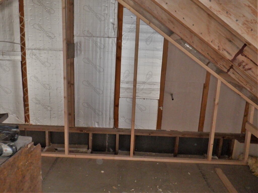
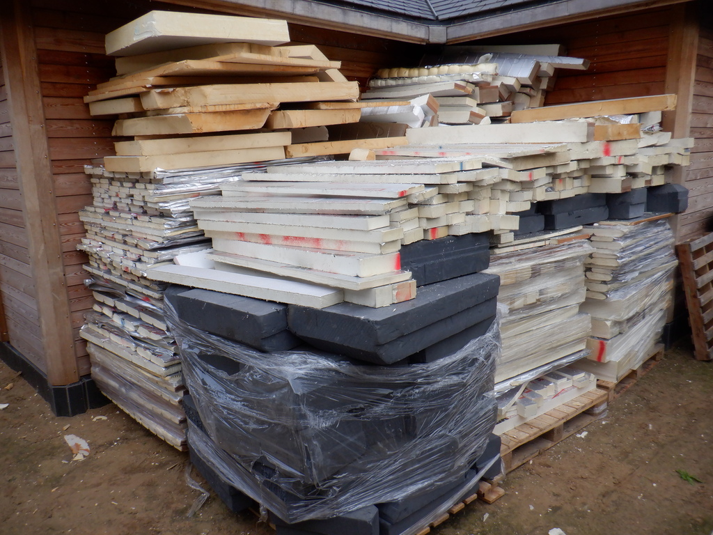
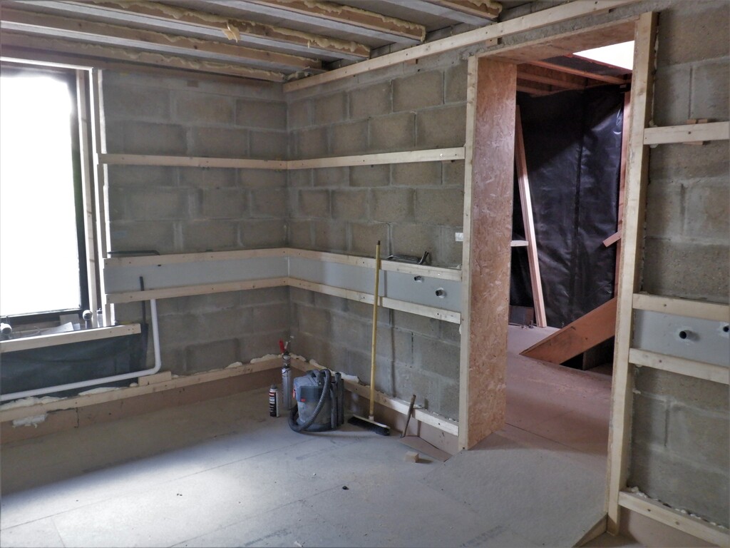
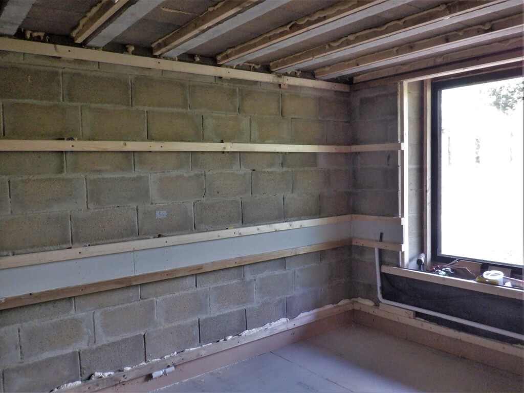
    While we still wait for our cheap insulation foam rejects to arrive, we got on with doing the Entertainment Room, which is our last ground floor room that we haven’t done yet. The Entertainment Room already has an internal walls and a ceiling, made using concrete blocks and suspended beams respectively. So, after emptying all our use full stuff ( i.e. “junk”) out (and putting it all in our Great Room and Kitchen), we proceeded to survey the state of the concrete walls, to see how flat and straight they are. They do wiggle in and out a little bit, according to our green laser line generator. We set the laser on the floor, right at one end of the wall and positioned it 50mm away from the surface. Then, adjusted the angle of the laser until we also have the beam just 50mm away from the surface at the other end of that wall. We did spot checks all over the surface to find how well, or badly, the individual blocks were set. We did this same procedure for all four walls and the results are as follows:

    • Large wall opposite the doorway: minimum=36mm and maximum=52mm
    • Left wall opposite the window: minimum=37mm and maximum 51mm
    • Doorway wall: minimum=32mm and maximum=50mm
    • Window wall: minimum=34mm and maximum=50mm

    Some of the worse offending blocks were in the upper corner where we were finishing off a row and near the top as well, and we couldn’t keep it straight. But it is not that bad, so we can handle that by putting spacers behind all the horizontal rails as we screw them into the concrete blocks.

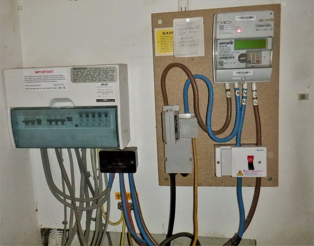
    The room is 4.75metres long and 3.78metres wide (approximately 15½ feet by 12½ feet) and we took careful note of where the joints between concrete slabs were, and decided that we would run eight long rails to minimise wastage and offset the first rail 400mm from the doorway side of the room, and then the usual 600mm spacing after that, terminating with a 300mm gap to finish off. The Energy Module is located about 3100 to 3200mm from the window wall and we want to make sure that we can build a small liftable hatch so we can service the equipment and inspect the underground tank via its inspection port. We have gone for a regular 600mm spacing along the long direction which will avoid all the joints in the floor slab.

    We cut two CLS planks to fit across the narrow sides of the room, marked off the rail positions (starting from that 400mm point and multiple 560mm after that one), drilled a set of 6mm holes in between those marks and making sure that we avoided the air disperser location which will be in the middle of the plank and we don’t want a screw going through our plastic module. We set up the laser in the middle of the room and set the height of our flooring framework to be at one block level, which is about 225mm, instead of the usual 378mm. We have decided to lower the floor level inside our Entertainment Room because it has already an lowered ceiling (the sound dampening concrete block and beam construction) so to make the room feel not so claustrophobic and maintaining the same 8feet clearance, we lowered the floor as well by six inches. There will be a slope built at the doorway so there won’t be any sudden steps etc. just a slope which will stretched out some two feet, starting from the Hall side of the doorway and stick into the room by about 400mm, to make is more friendly for anyone but especially for wheelchair users too.

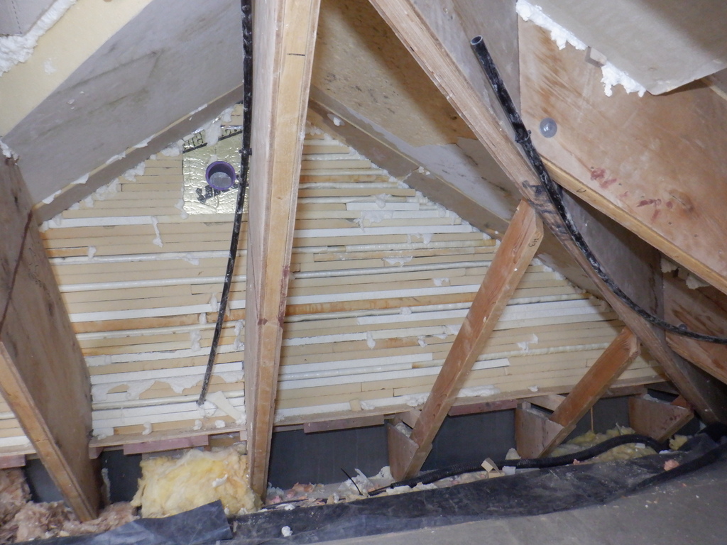
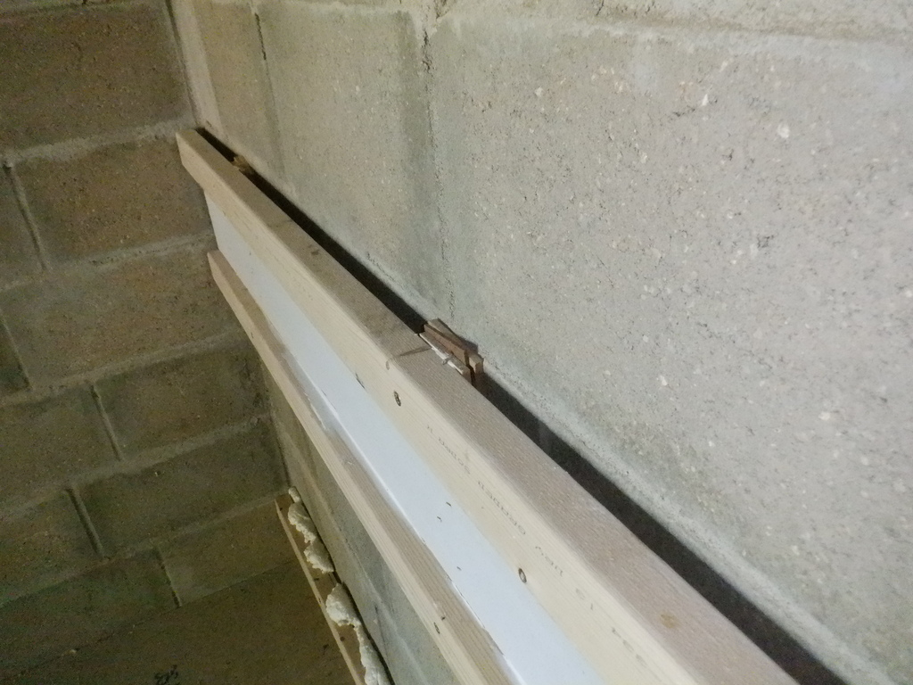
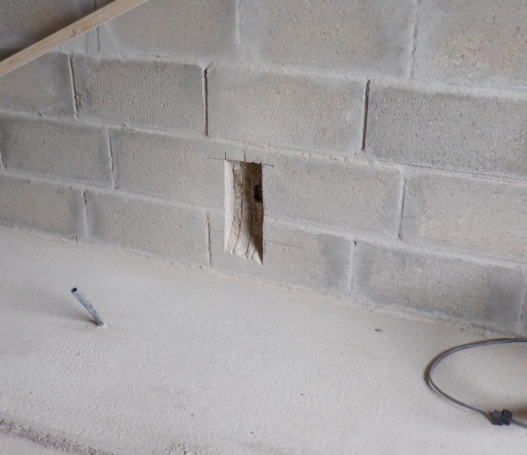
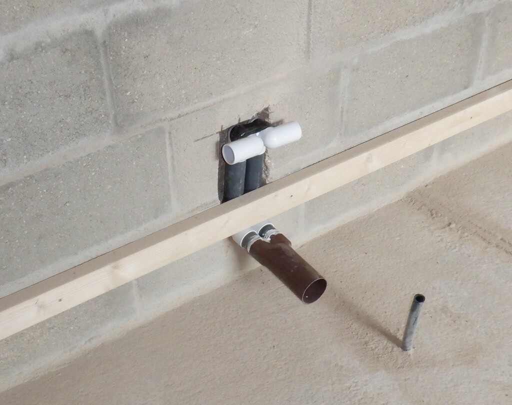
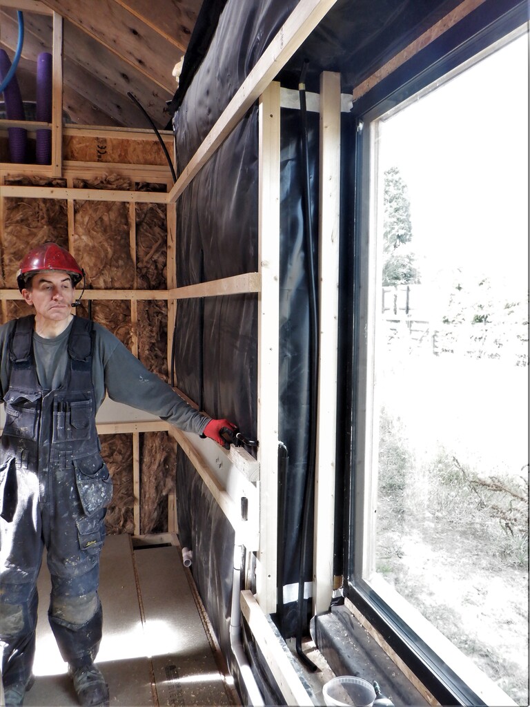
    The next job is to cut four cavities into the concrete blocks themselves, to allow for our air dispersers to be routed from underneath the flooring and bypassing the floor joist and let the air into the Air Channel. We used a diamond cutting disc to slice 50mm into the block and then chiselled out the chunks. We made it 120mm wide to make room for the twin plastic pipes to fit. We will also spray some PU foam to help stick it into the wall and insulate it a bit from the cold concrete blocks. The slot is about 250mm high and it was very very dusty, generating a huge cloud of grey concrete dust. We were wearing very good dust masks thank goodness!

    Starting on the Entertainment Room

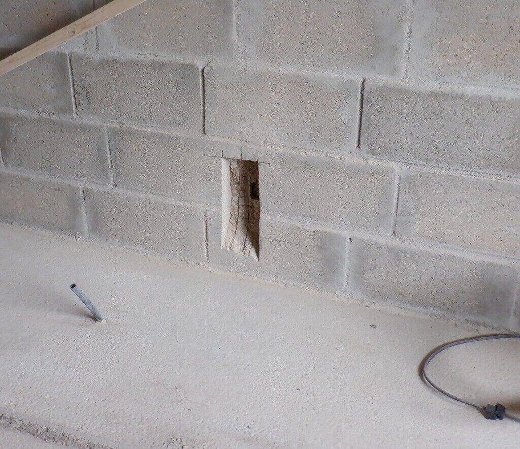
    Channel-hacked-the-the-Entertainment-wall

    We also made the four dispersers as well, doing the usual method of trimming down the elbow corners and gluing it all together. So we could test the new slots to make sure that they had room to fit properly.

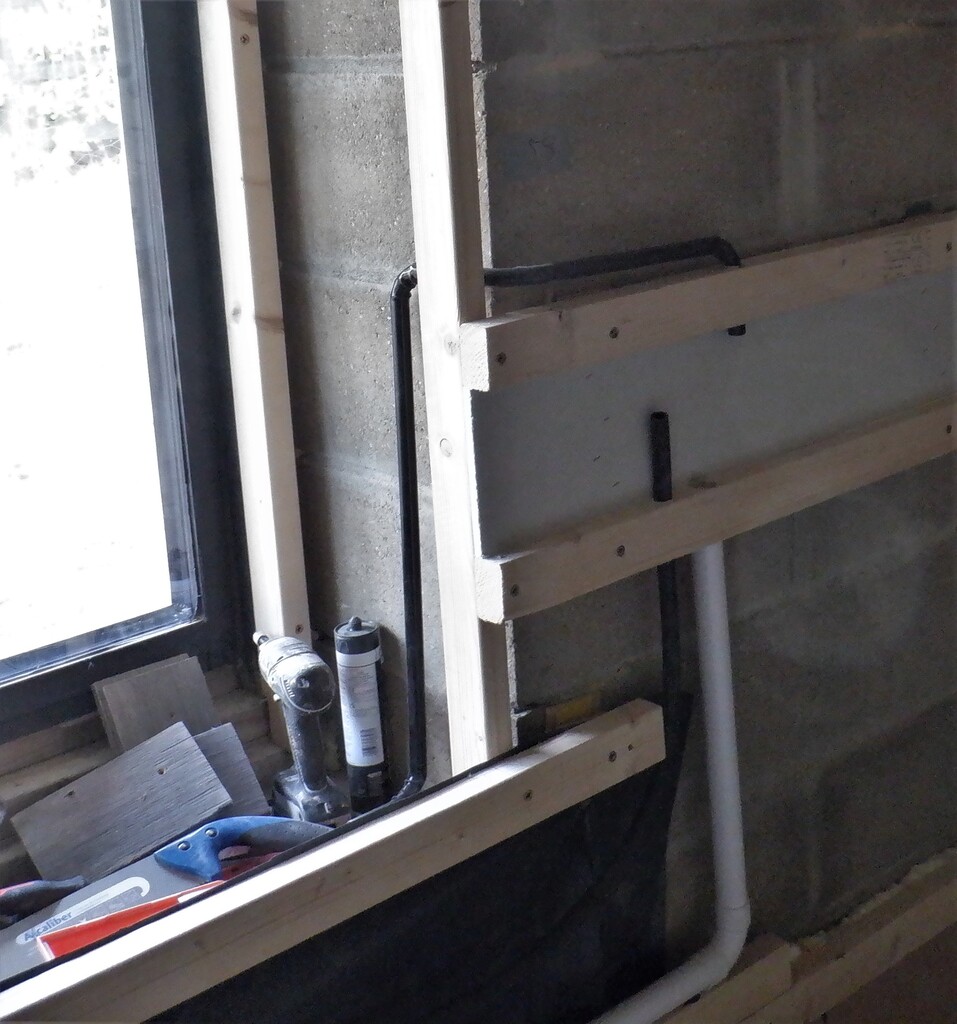
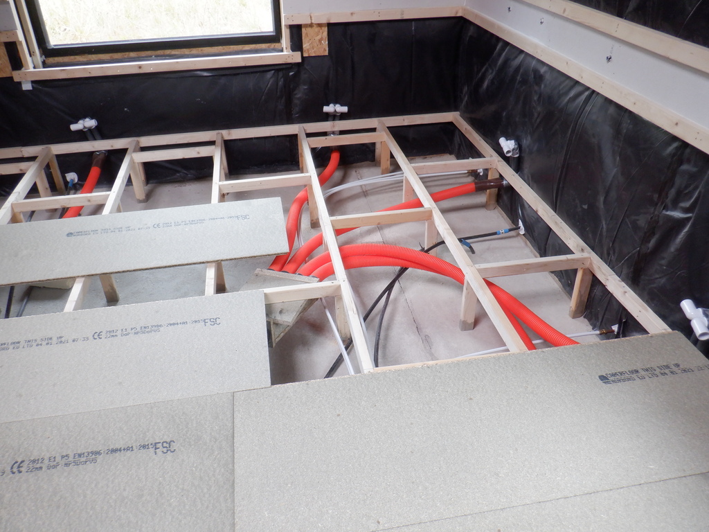
    We went around drilling all the necessary holes in the concrete walls for all four sections of the floor joist support batten, putting in a 7mm plastic wall plug and screwing it down tight using 100mm long 6mm screws whilst putting the air distributers in. We also put on a large washer to help spread and grip the wooden pieces tight to the walls, especially that we had a larger clearance holes through the wood so we could tap the joist a bit up or down, to get it as accurate as possible against our green laser line level.

    Starting on the Entertainment Room

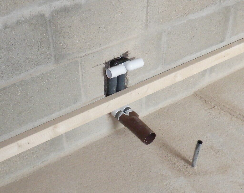
    Air-distributer-in-the-channel

    Next, we chopped up 62 legs that the whole floor will need, with 19 of them having one corner sliced off to allow for the mortar on the bottom of the walls. All of them were then dipped in our coloured timber preservative liquid, to make sure that the timber will last for decades, even if we had a water leak so it won’t affect the wood.

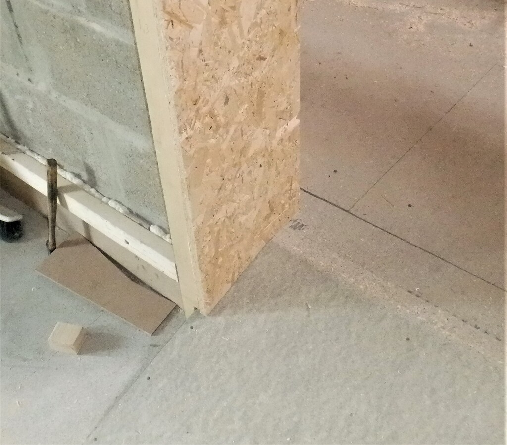
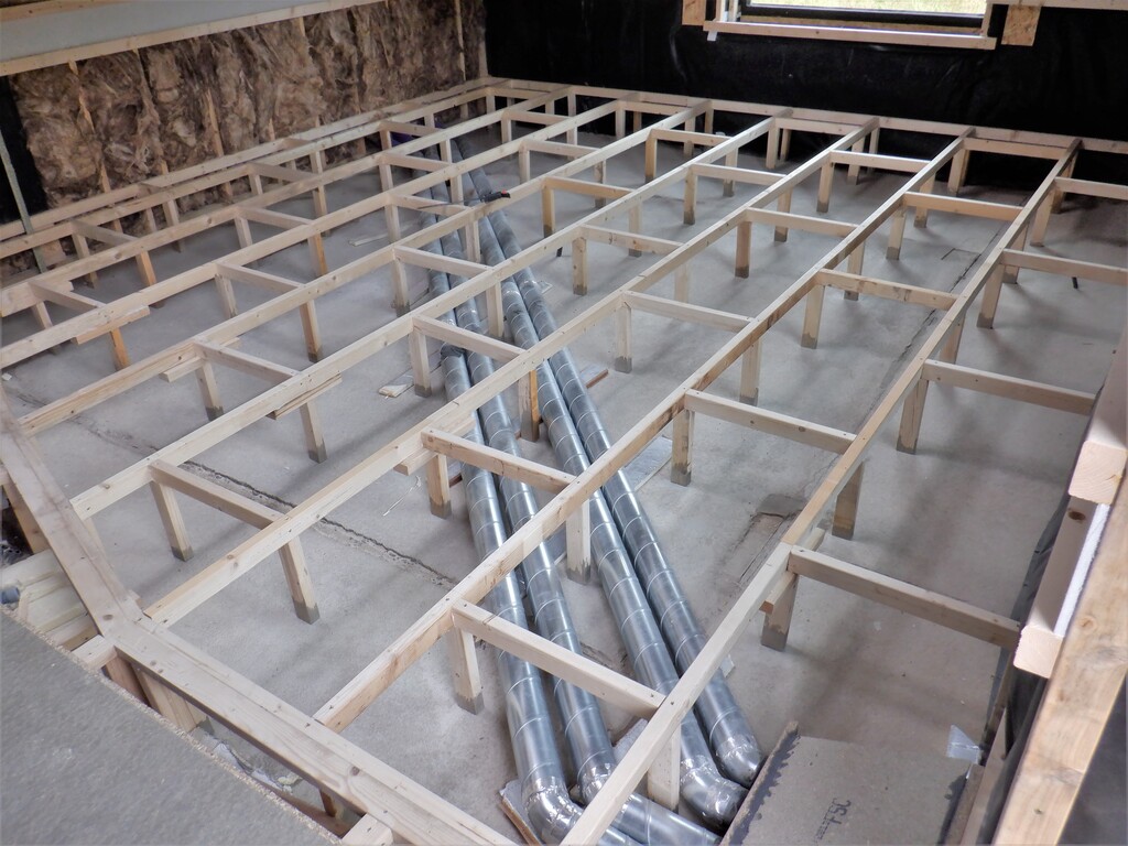
    Then, we started by the doorway and put in the first rail at 360mm spacing and cut a piece 4665mm long and put in seven legs along its length and two specials for the ends. Using this rail, we then built the ramp for the doorway using three pieces of CLS timber, with angles cut on their ends to connect to the bottom rail and also joining up onto the hall framework too. We also put in trimmed filling in pieces in between these sloping rails, with the surface planed so it matches the slope in general, so that the top and bottom edges of the ramp will be fully supported. Finally, we stuck in two additional legs to help support the two outer sloping rails so the joints will not creak in the future. We topped the whole thing off by laying down a floorboard piece, measuring 880mm wide by 590mm long, with a shallow 18degree angled cuts for the top and bottom edges so that we don’t end up with gaps in our flooring.

    Then, we continued with mounting the rest of the floor joists, six more rails, each having seven legs under each one and we got that all done, including the horizontal noggings every 1200mm.

    Starting on the Entertainment Room

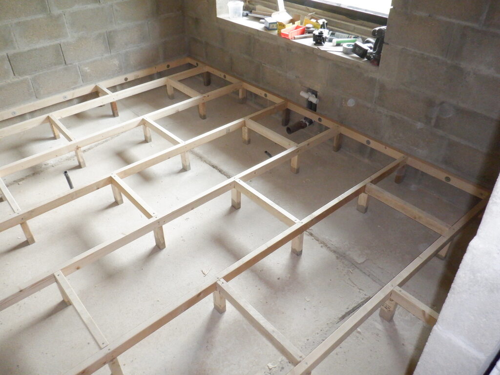
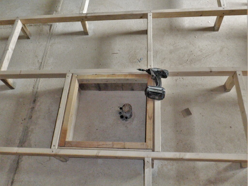
    Entetainment-Floor-grid-1

    Starting on the Entertainment Room

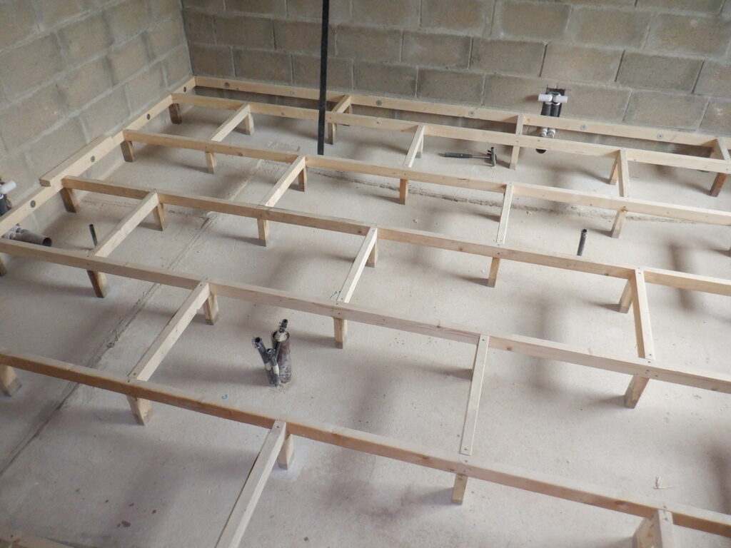
    Entetainment-Floor-grid-2


    Next, we built a box around the Energy Module collection of pipes and conduits coming out of the concrete floor slab so we put in four plywood pieces around the four sides, lined the bottom with 50mm of PU foam and put in additional rail around the top edge so our lid can sit on something solid.

    Starting on the Entertainment Room

    Energy-module-equipment-box

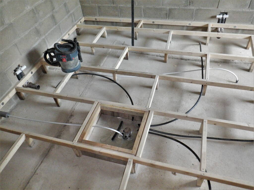
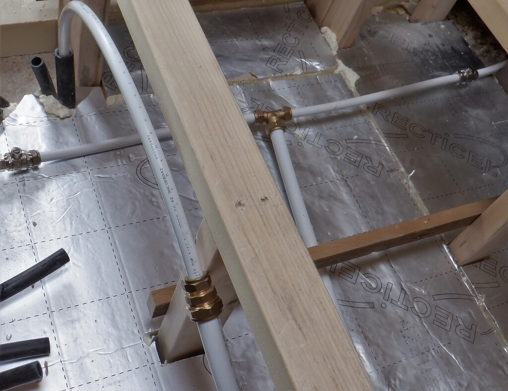
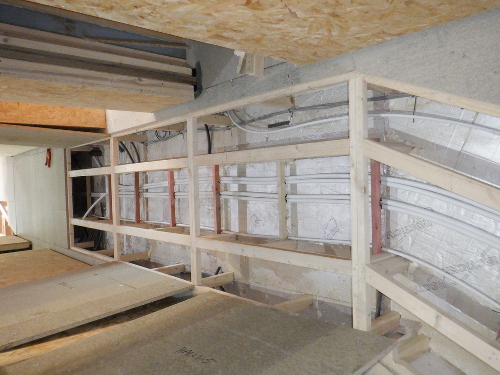
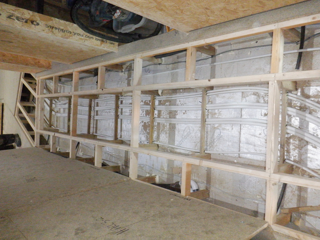
    The conduits for the temperature probes were threaded around the legs and framework so that all four of them were routed over to the plumbing box and poked through the plywood sides, ready for threading the actual temperature sensors down the conduits and measure the state of of the environment around and inside this Energy Module.

    The filling pipes were fitted, being 15mm water pipes, and they were routed towards the hallway. This meant that we drilled a couple of 65mm diameter holes through the concrete blocks and pushed in some short length of pipe insulation to protect the energy in the water when it is transferred from inside the Energy Module and the Utility Room.

    Starting on the Entertainment Room

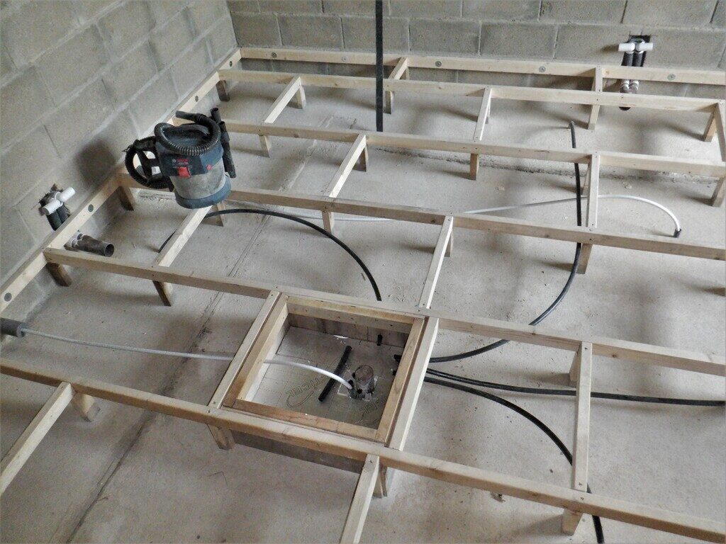
    All-the-pipes-and-conduits-in-place

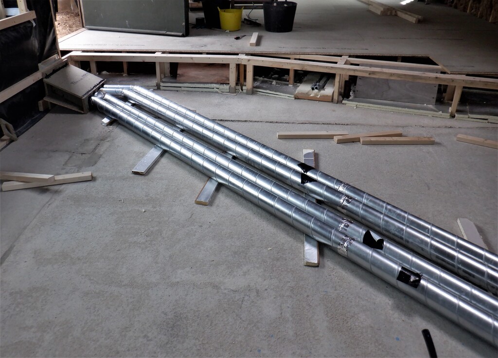
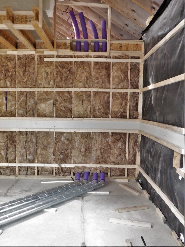
    Then, we built another air distributor module to be connected to a 100mm feed off the main air duct back in the Hall, coming down the hall towards the front door and then turning into the Entertainment Room under the doorway itself. The distributor module is the usual affair of one 100mm input pipe, being squeezed and spread out to four 50mm connections, to be sent around the room.

    Oh yes, we just remembered that we needed a data conduit to be fitted to our central plumbing box and routed the other end out in the hallway under the doorway. This will allow us to feed a couple of cables through to connect our house network and provide electrical power to the little computer that is monitoring the vital signs of our buried Energy Module.

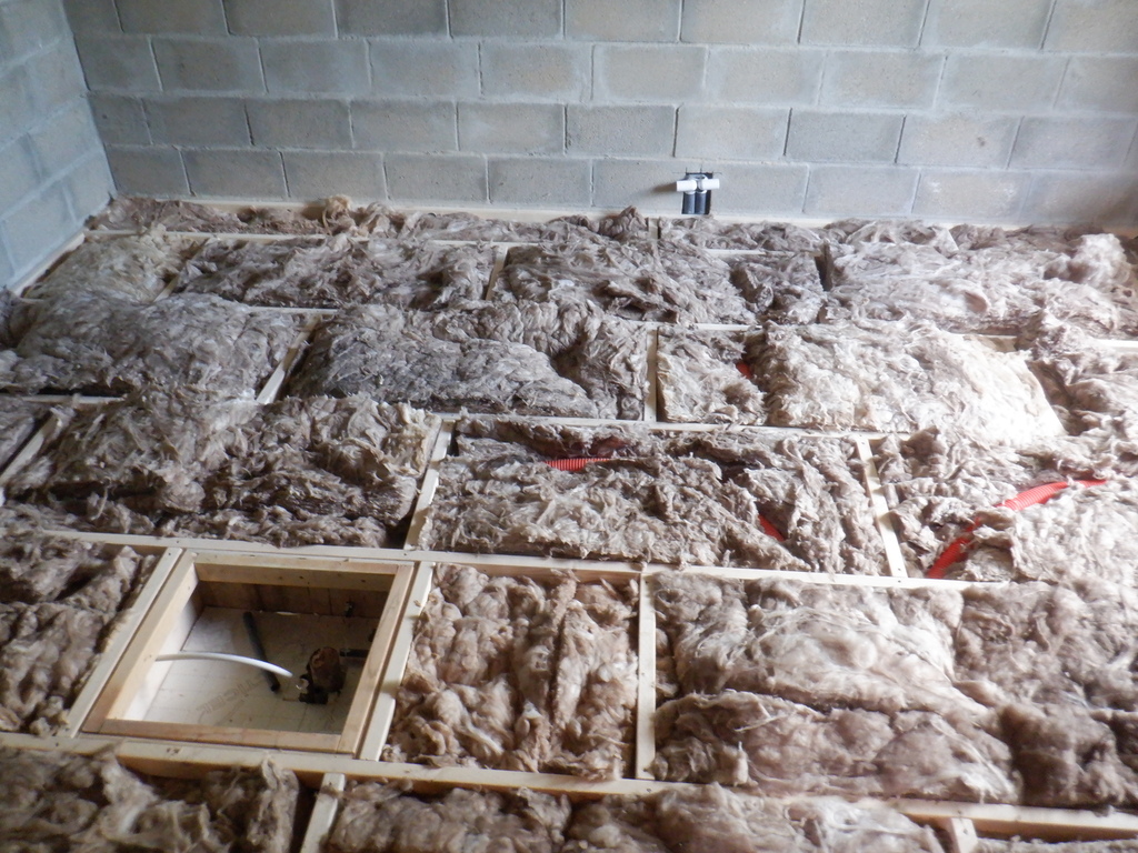
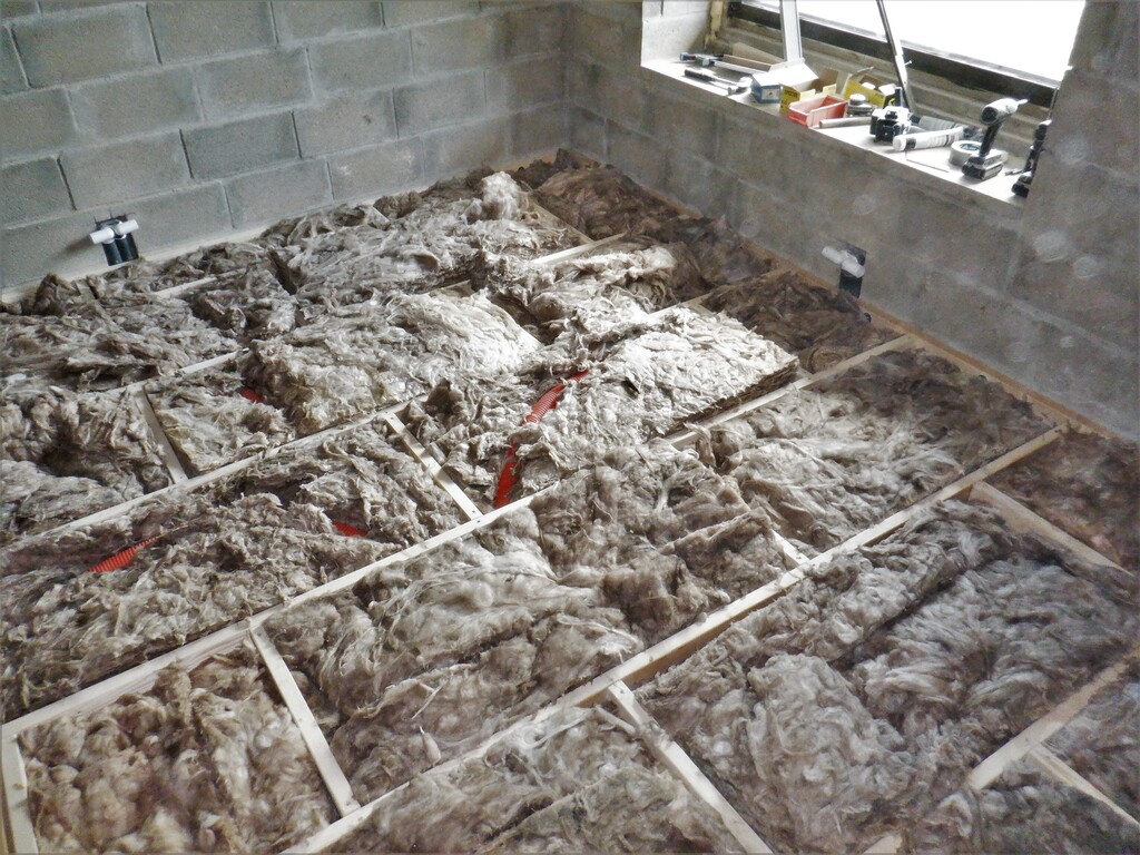
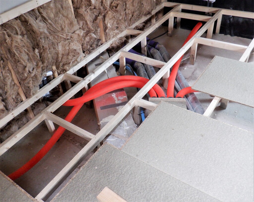
    This concludes all the bits and pieces going under the floor so we loaded in two layers of 200mm thick glass wool strips, laid flat. These strips would be 400mm high but when laid down, they only just came above the wooden rails which is 235mm off the floor, which is good to provide a much better sound absorbing layer.

    Starting on the Entertainment Room

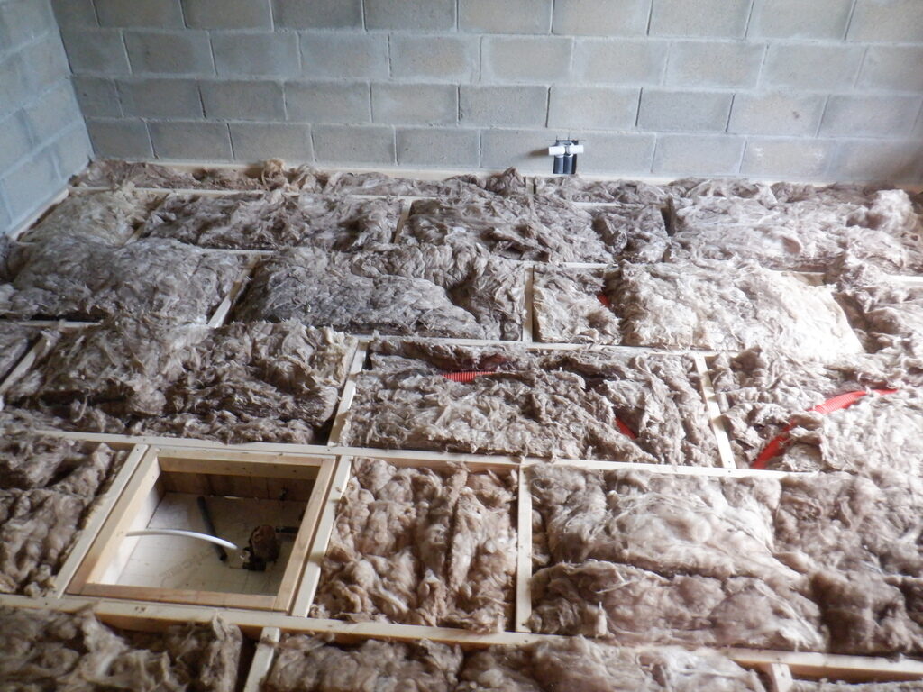
    Insulation-in-the-floor-1

    Starting on the Entertainment Room

    Insulation-in-the-floor-2


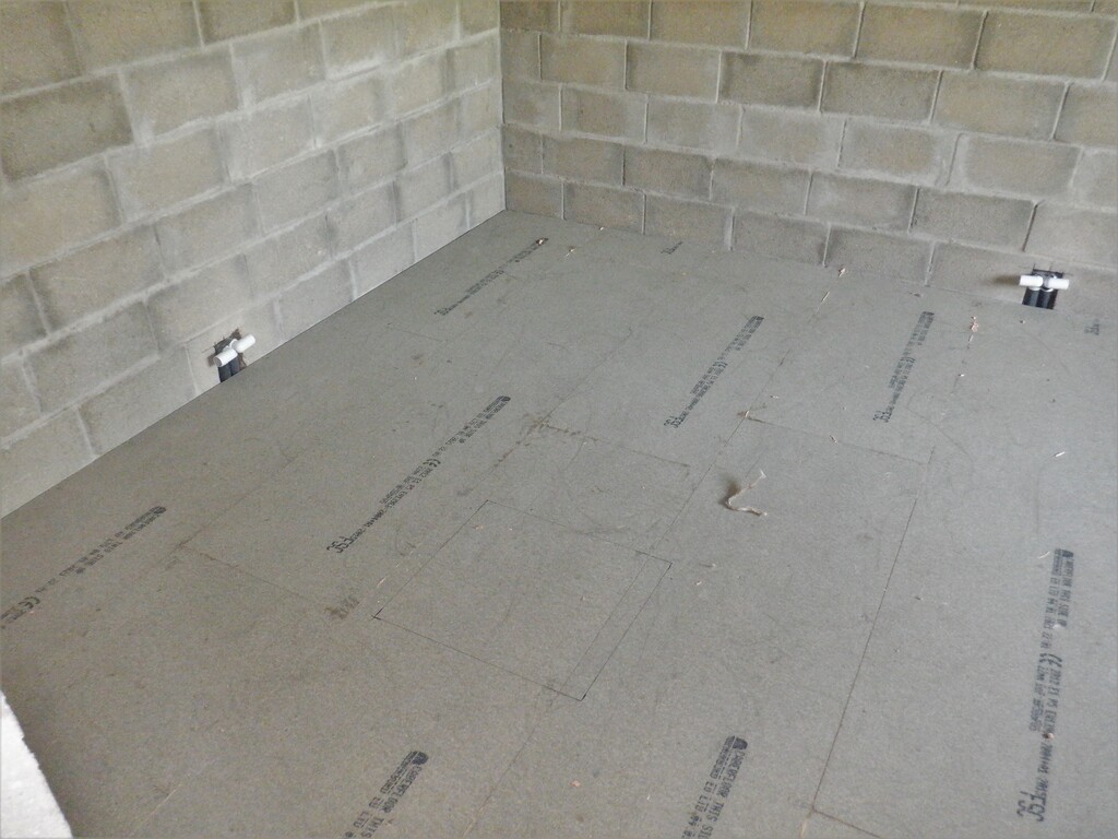
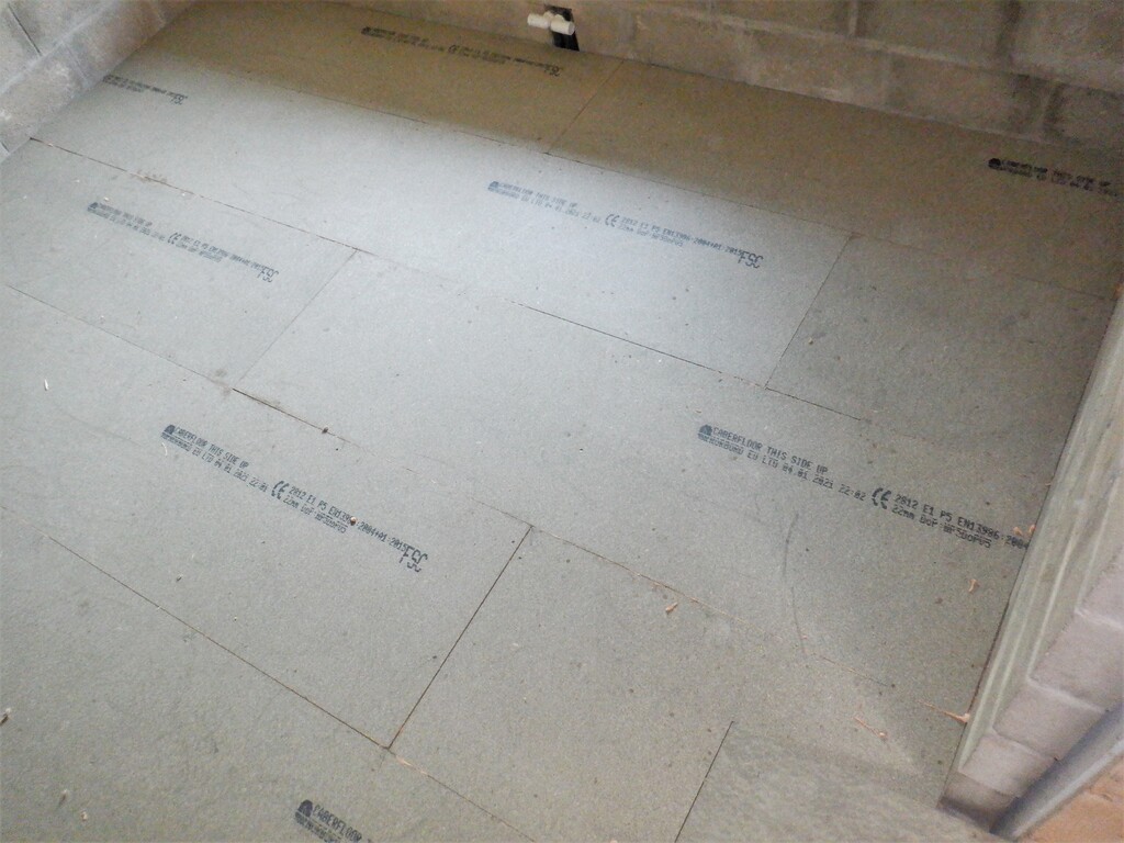
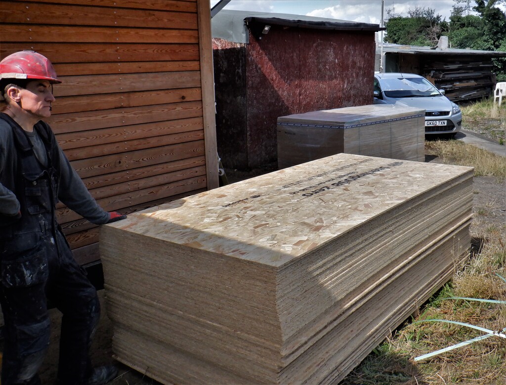
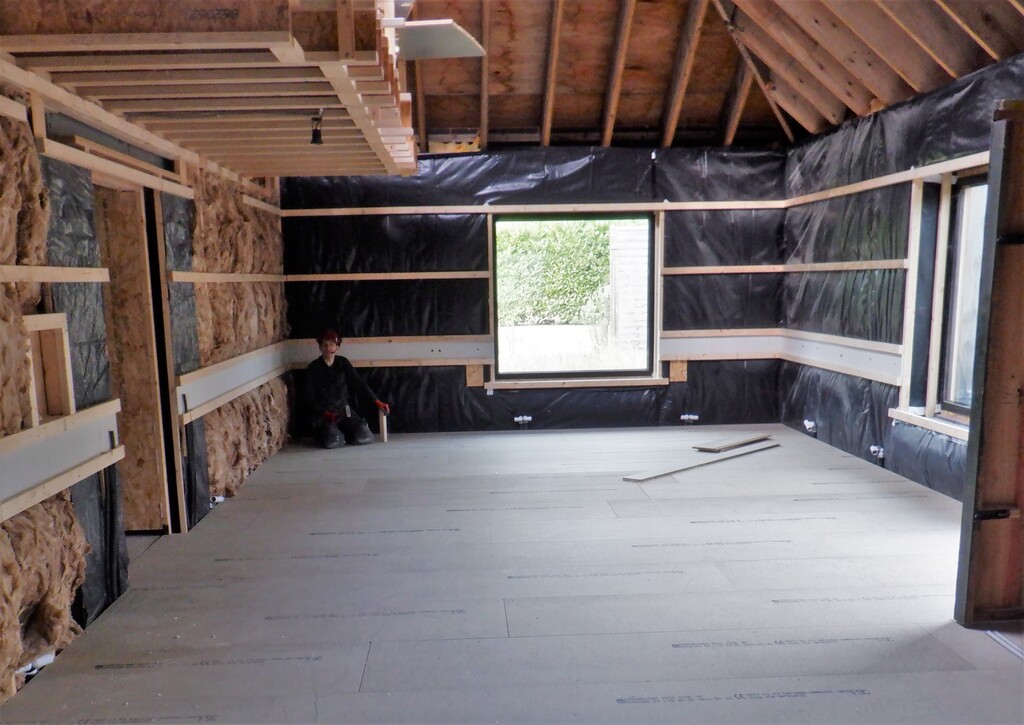
    Now, we went ahead and laid down the 22mm thick floorboards, starting left of the doorway and worked our way across the room towards the window. The floorboards were glued and screwed down nice and solidly. The width of the room meant that we had to throw away fairly large pieces especially when we came to the ramp where we decided to start over again with a full length board, to make sure that the floorboards in the doorway is well supported.

    Starting on the Entertainment Room

    Enetertainment-room-floor-finished-1

    Starting on the Entertainment Room

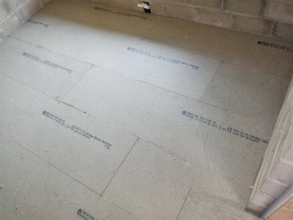
    Enetertainment-room-floor-finished-2


    This concludes this stage of building the Entertainment Room, we will carry on with putting up the wall rails, getting them levelled and flat including putting in the Utility Channel and the OSB wall boards and may even get the ceiling done too.

  • 85 Sheets of 11mm OSB and 50 Sheets of 18mm OSB boards

    We had a delivery of additional sheet materials to add to our store of 11mm and 18mm OSB (oriented Strand Boards). We could calculate what we have left to construct for both the remaining downstairs rooms and also upstairs plus the flooring. We counted what we already had and we estimated that we needed another 50 sheets of the 18mm thick boards and another 85 sheets of the 11mm thick boards. They came on two pallets and we unloaded them over three days and put them all in our sheet storage room a.k.a Bedroom Two!

    85 Sheets of 11mm OSB and 50 Sheets of 18mm OSB boards

    OSB-Delivery

    85 Sheets of 11mm OSB and 50 Sheets of 18mm OSB boards

    OSB-Moved-to-Bedroom-2


    Mind you, the builder merchant did forget 1 sheet of the 11mm board and they had damaged the bottom sheet of 18mm with their forklift truck (or someone did). We will send them a request for a credit to be added to our account.
    85 Sheets of 11mm OSB and 50 Sheets of 18mm OSB boards

    Damaged-OSB


    The prices has risen considerably in just 18 months, we paid £17 for each 18mm type board last time and now we had to pay £23 each!! A 30% rise!! A few years ago, we only paid £13! Crazy World We Live On Now!
    So we are going to order all our standard plasterboard (which is not going on the walls but under the floor!) and Fermacell (an engineered high performance plasterboard) in the next week or so and beat the next price rises that are due in September.

  • Second Half of Great Room’s Floor is Finished Including Ducting and Pipes Underneath

    We started the second stage of building the flooring for the Great Room by fetching down from our upstairs timber storage, 10 nice straight pieces. We then marked the 600mm markings on eight of them which will be where the support legs will go. Then, we laid out these eight lengths, ready to be our joists for the framework, putting them down on the concrete itself. We did this because we needed to get the air ducting laid and positioned so it connects to the exhaust air from the Conservatory and routed diagonally across the room and up to the First Floor to join into the main Air Duct that will travel through the house towards the Utility Room. This bridging section going underneath our floor needs to fit in between all the support legs, hence why we had marked out those positions and we soon realised that we had to shift things around a bit. The set of eight joists were spaced so that the bigger gap was next to the Kitchen side of the Great Room but we discovered that one of the joists and its support legs landed right over a joint in the concrete itself. So we moved everything over by 300mm so that the bigger gap is now over next to the Conservatory side of the room and that made it much neater. Then we could see that the metal ducting, two joined together making four lines stretching diagonally across the room was going through the support legs locations too. This meant another adjustment in our arrangement but this time, we shifted the support legs positions along the joists by 300mm which also turned out to be an advantage by avoiding another joint in the concrete slabs but in the other direction this time.

    So this allowed us to then construct another Air Splitter module that joined to the chimney that is coming down inside the wall between the large window and the Conservatory French doors, bringing the old exhaust air from that room. It was a case of carefully cutting and slicing several pieces of our chipboard pieces and shaping them so that we could plug in the set of four metal pipes into this module and draw the air away. It was quite fiddly but we managed it after a couple of days of work.

    Then of course, we had to remove all our CLS planks out of the way so we could lay down properly the eight metal pipes, join them to the four purple flexible pipes coming down inside the Kitchen wall and four double length joined and trimmed with small pieces of short pipes to finally connect to our new splitter module. We sealed all the joints with aluminium tape and Stixall glue.

    Second Half of Great Room's Floor is Finished Including Ducting and Pipes Underneath

    Conservatory-Air-crossing-GR-and-ascending-to-FF-void-1

    Second Half of Great Room's Floor is Finished Including Ducting and Pipes Underneath

    Conservatory-Air-crossing-GR-and-ascending-to-FF-void-2


    We now have that particular air ducting completed and we can continue to build the floor framework over the top of it. It took us the next two days to complete that wooden structure, putting in eight joists and a collection of posts and noggings and it went in quite well. The metal tubes were successful in their location, only had to move a couple of legs a centimetre or two to avoid them.

    Second Half of Great Room's Floor is Finished Including Ducting and Pipes Underneath

    GR-Floor-grid-complete

    Next, we put in the conduits for the temperature probes that surrounds the Energy Module, another six of them, to add to the other four plus the other local ones already in place so we can put in sensors to monitor the performance of this large tank. Then, all the water type pipes were laid in, four of them using 15mm direct water connections going to the external world in various forms and then two more thin irrigation waterlines going up to the Eves, so these were 20mm conduits to help feed this pipe through. Next, was the hot water twin pipes, travelling on its last stage of its long twisty journey around the house, to go diagonally across the room, next to the metal air ducts, poke through the kitchen wall and arrive inside the plumbing box located in the Kitchen where the sink and other water related services are.

    The cold water, the 32mm header tank water supply, then came across the room and join alongside the hot water to enter the same plumbing box and then finally, a single 15mm mains water pipe coming all the way from the Utility Room and also coming around to enter into the plumbing box too. This will provide fresh drinking water for the Kitchen.

    Finally, one more 15mm water pipe was inserted into the Energy Module, threaded down a sticking up 25mm pipe coming through the concrete and going back to the Utility Chamber to join with its twin, to get married to a larger 22mm pipe going off to the Utility Room. We also inserted a second 22mm water pipe alongside this one, but starting slightly further down the hall where our second largest Energy Module is located under the Kitchen and Bedroom One, both going all the way to the Utility Room.

    Second Half of Great Room's Floor is Finished Including Ducting and Pipes Underneath

    GR-EM-Fill-connections

    Second Half of Great Room's Floor is Finished Including Ducting and Pipes Underneath

    EM-Pipes-running-to-the-Utility-Room-1

    Second Half of Great Room's Floor is Finished Including Ducting and Pipes Underneath

    EM-Pipes-running-to-the-Utility-Room-2


    The last job to do under the floorboards is to put in the air pipes to provide fresh air for this half of the Great Room, another eight air distributors located around the edge of the room, two along the Kitchen wall, three along the “A” wall and the final three along the Conservatory wall. These outlets are fed and grouped into four separate 50mm conduits that goes back to a splitter module which has a 100mm conduit connected to it and the other end coming from the Utility Chamber, ready to be connected to the main Air Duct.

    Second Half of Great Room's Floor is Finished Including Ducting and Pipes Underneath

    GR-PA-Air-distribution-point

    Second Half of Great Room's Floor is Finished Including Ducting and Pipes Underneath

    GR-Hot-Cold-water-Fresh-Stale-air-all-in-one-place


    Finally, we carried on laying down the floorboards for the rest of the room, again, not glued down, or screwed either. We knocked each row securely against the rest of the floor, to encourage the joints to close up nice and tight. But the last row is only a half width piece and we have not cut an accurate piece to go into this space, but just laid down a couple of left-over half boards to fill the gap, to make it safe.

    Second Half of Great Room's Floor is Finished Including Ducting and Pipes Underneath

    GR-Floor-finished

    One of the last task to do while we remembered, was to insert a collection of conduits and pipes around the windows so the wires and cables can carry on along all the Utility Channels. We did also the conduit that goes down into the bottom module underneath the window where the blind mechanism is to be located.

    Second Half of Great Room's Floor is Finished Including Ducting and Pipes Underneath

    GR-Window-conduits

    This concludes the work for the Great Room for the time being!! We won’t get back here until we have fully finished filling in the Roof Rafters and putting up the ceiling panels etc. After that, we can lift the floorboards and “throw” all the PU foam rubbish under it! Next, we will make a start on the Entertainment Room while we wait for this insulation PU foam pieces to arrive.