Category: Phase 5

Building the internal framework of all the rooms, 1st floor joists and gallery.
This also includes building the sound proof Entertainment Room.
Plus also installation of insulation, OSB boards and construction framework for upstairs rooms too

  • Started On Building Bedroom Two plus Running Water Pipes Under Floor

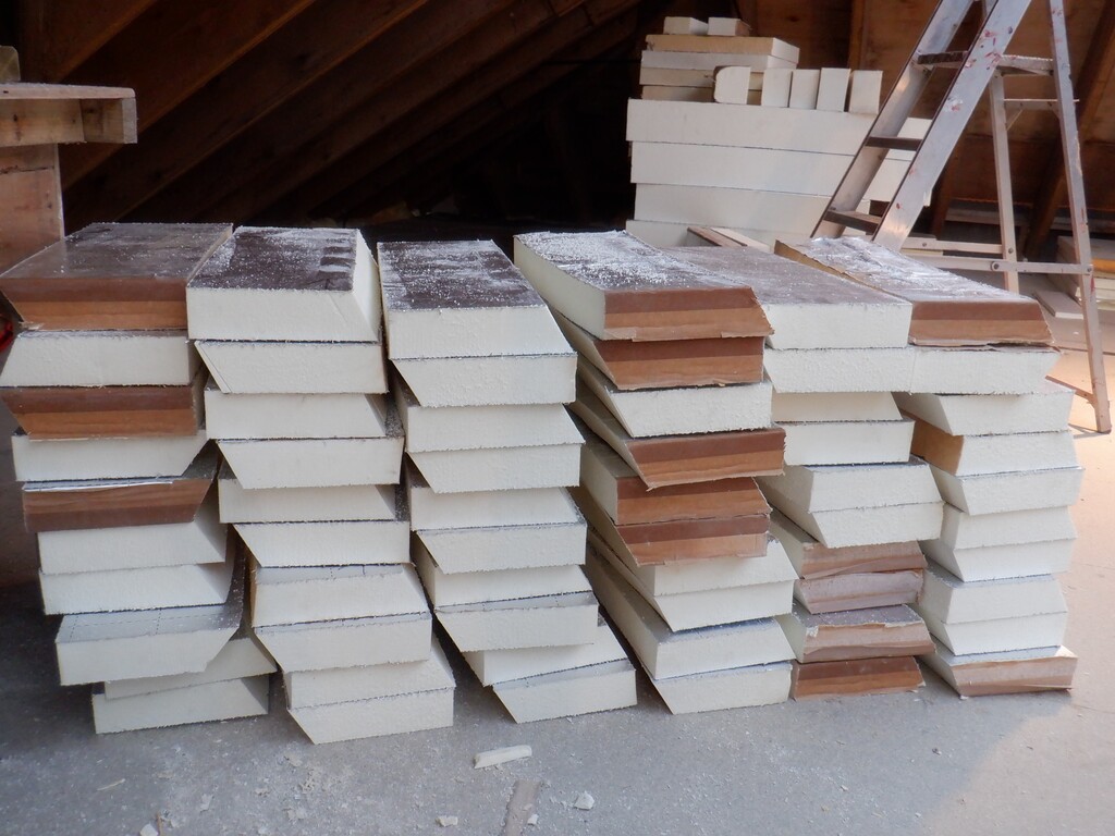
    This is a long single report to cover the work during the month of December on Bedroom Two and other jobs. We wanted to get going on creating Bedroom Two so we could move the final loads of PU foam rubbish we got stored outside in the alcove in between Bedroom One and the Great Room’s windows before Christmas arrived.
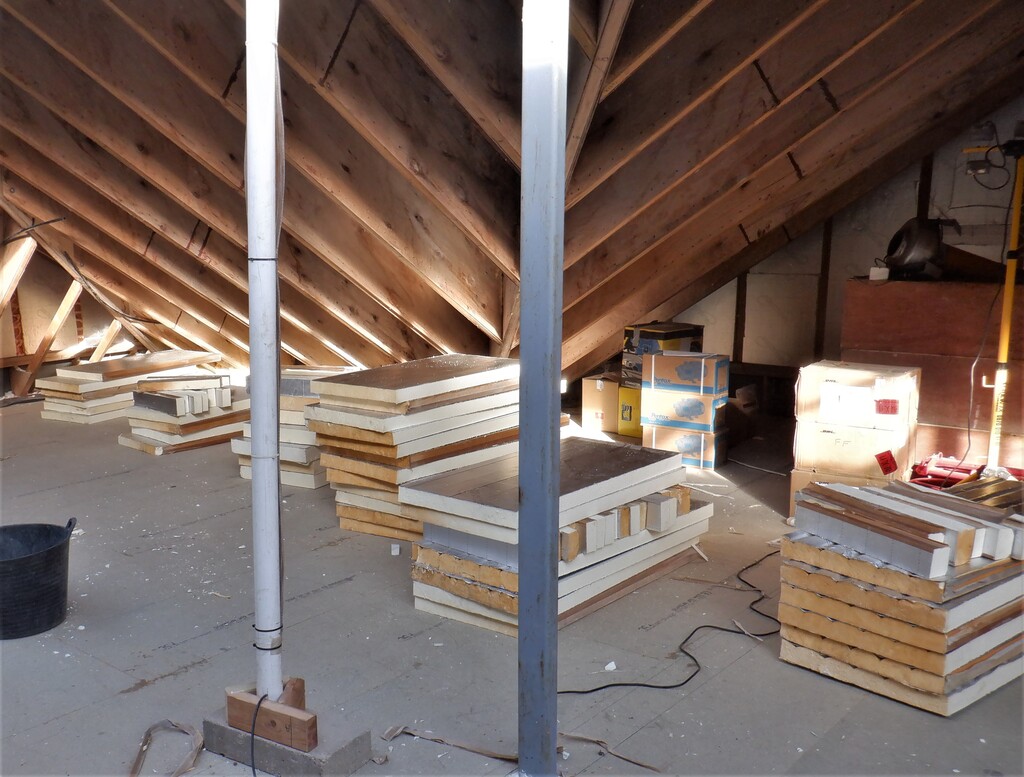
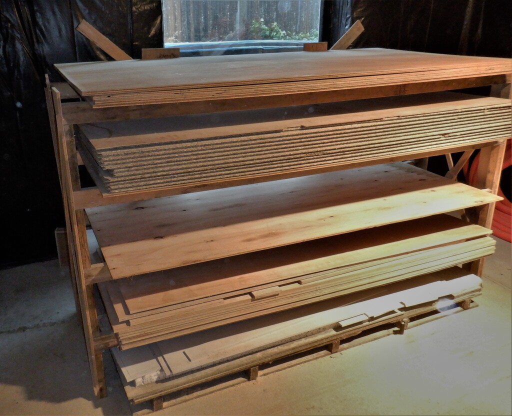
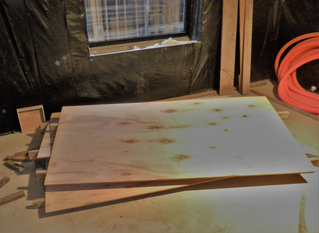
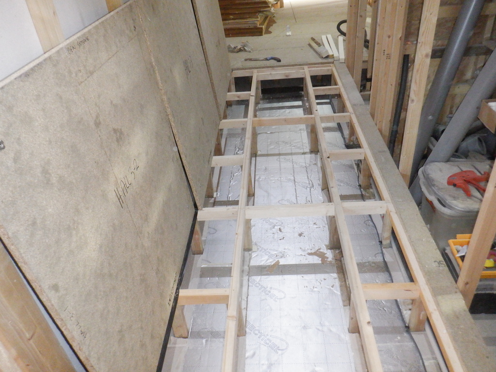
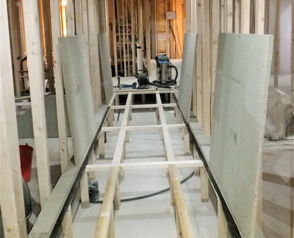
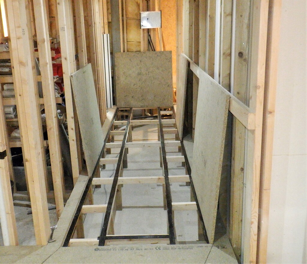
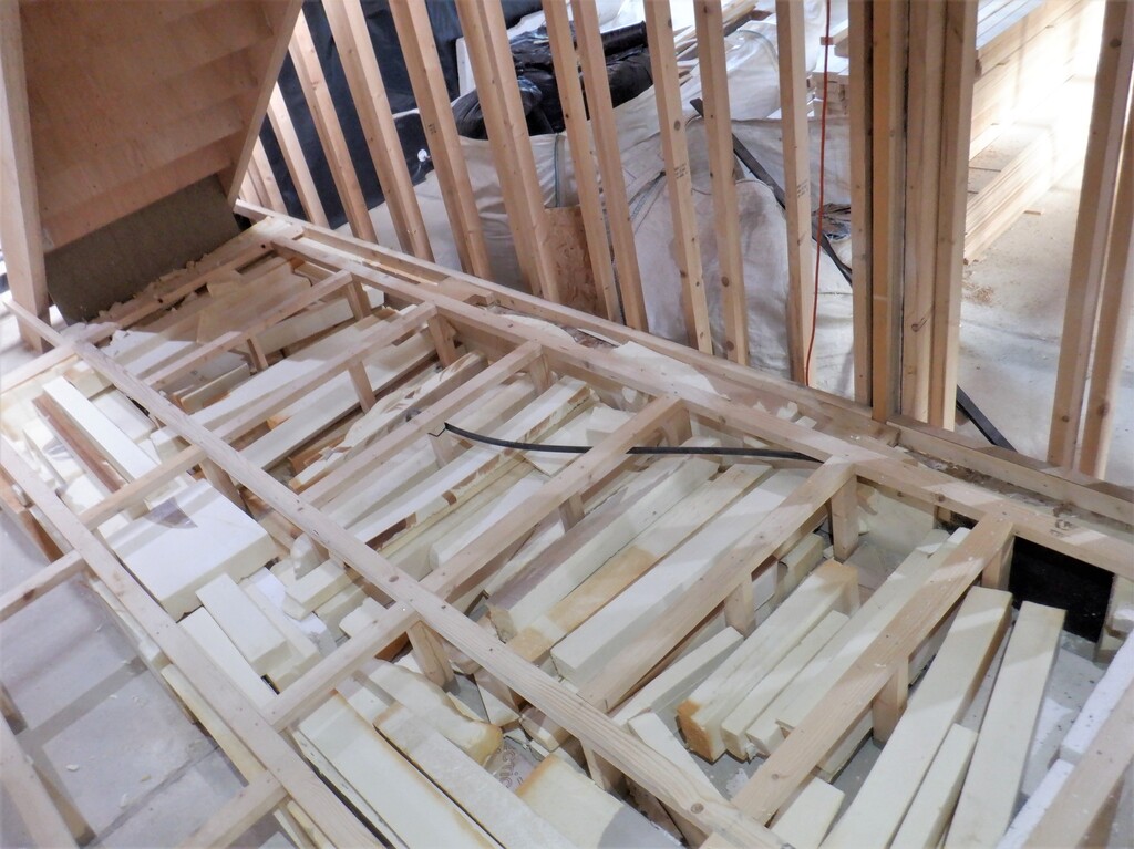
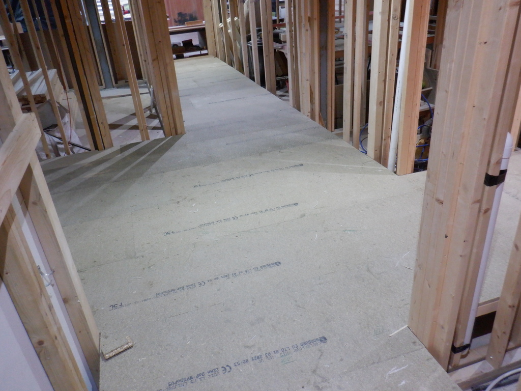
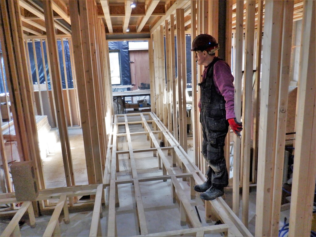
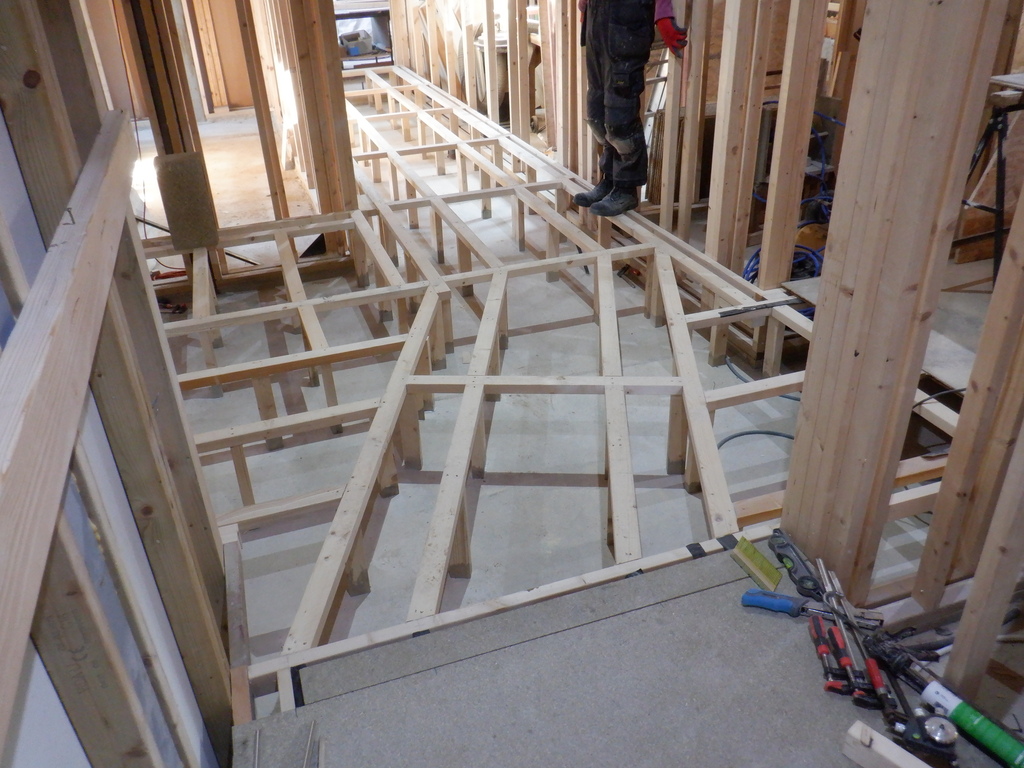
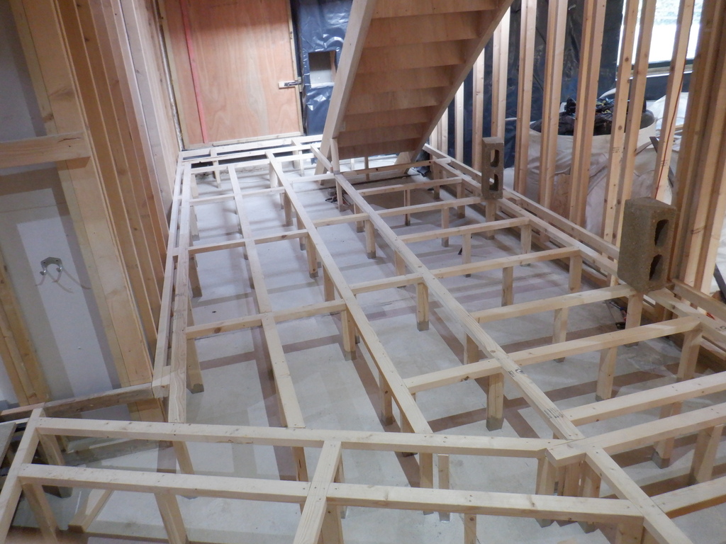
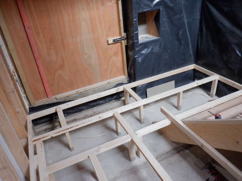
    So one of the first steps was to clear everything out of the room including the huge pile of sheet materials, which got all moved into Bedroom One. Then the horizontal rails, using more of our 63mm CLS timber pieces, were positioned on all the four walls, using the green laser level to ensure consistent height, the level of our flooring. Next, was putting single piece CLS timber across the room, spaced apart by a uniform 600mm distance, each piece being just over 3700mm long. Each one having a leg fixed at every 600mm along the joist for support. A section near the on-suite doorway was doubled up around the floor joist support because this will have a removeable lid to gain access to the control devices and plumbing modules that will serve the various features in the ensuite.

    Started On Building Bedroom Two plus Running Water Pipes Under Floor

    Floor-grid-in-Bedroom-2


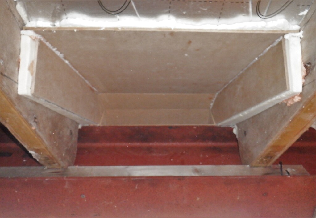
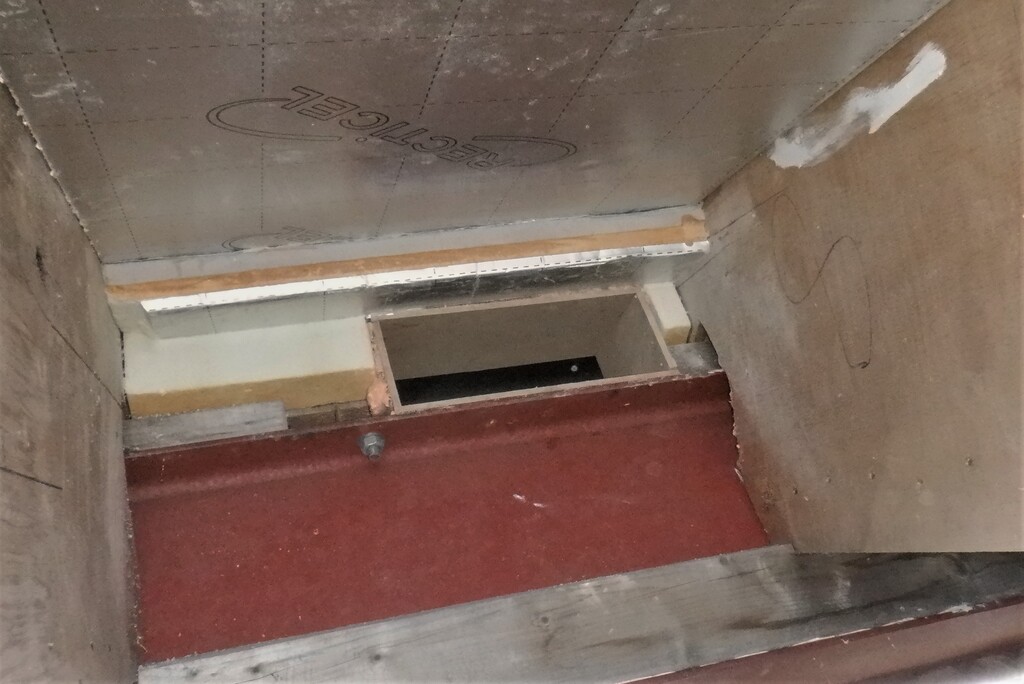
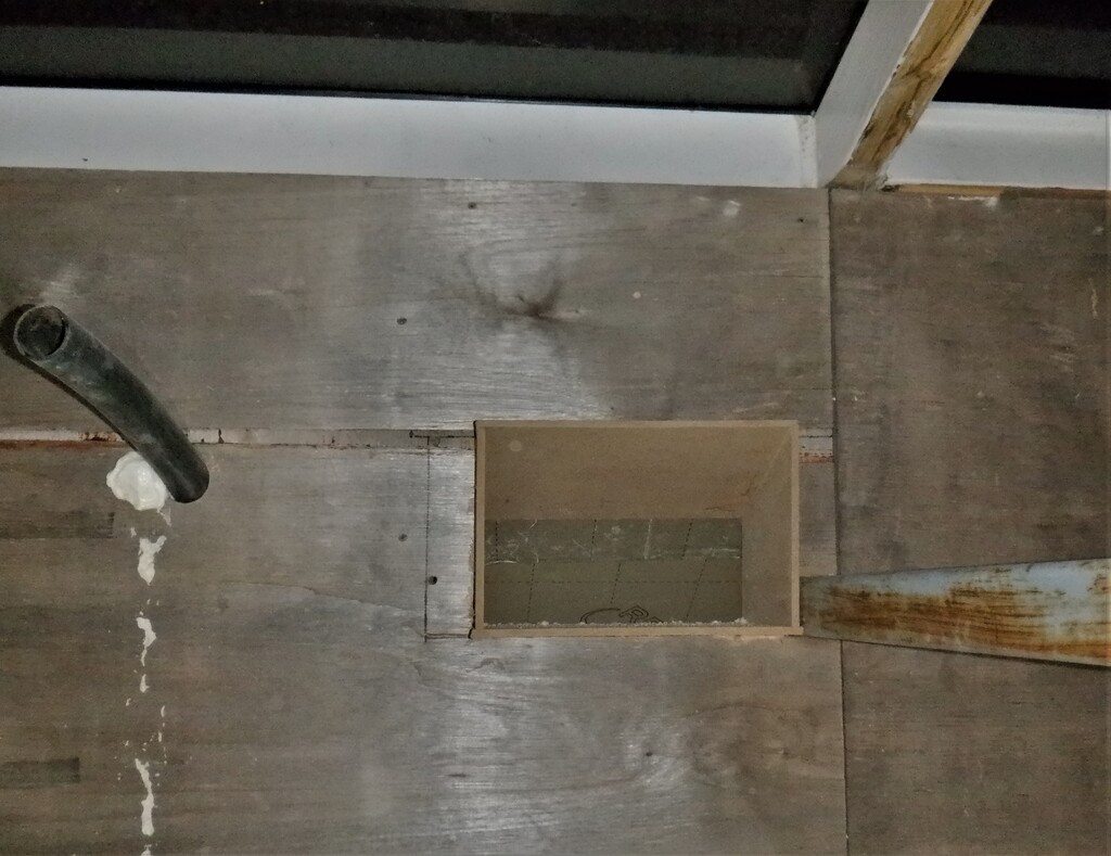
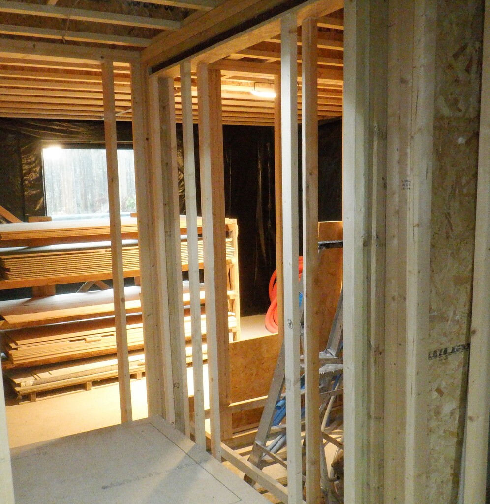
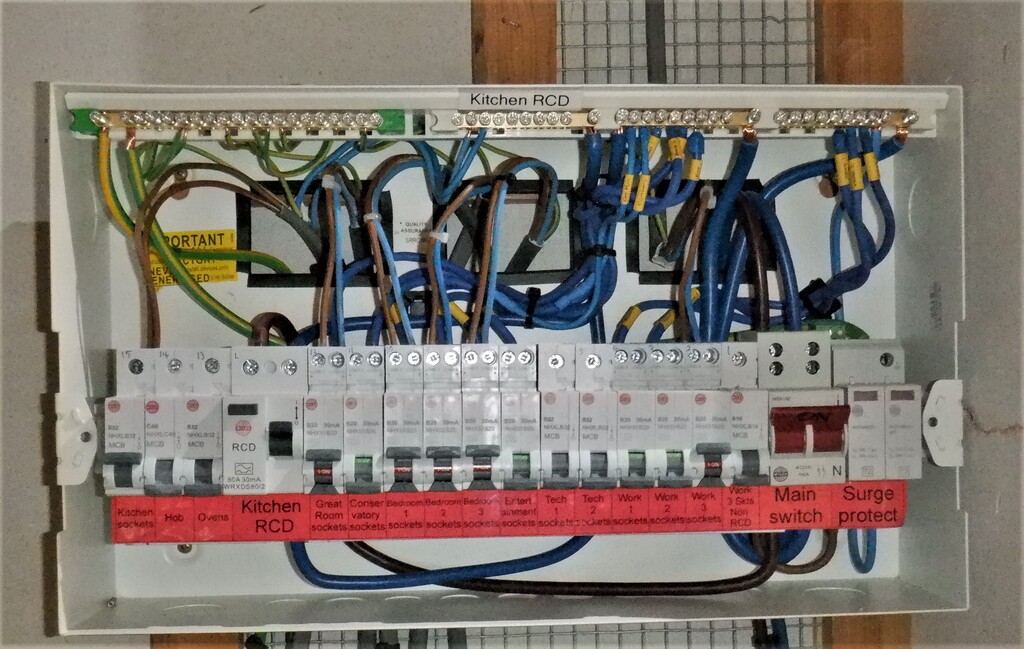
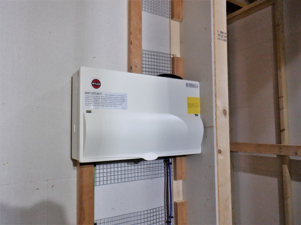
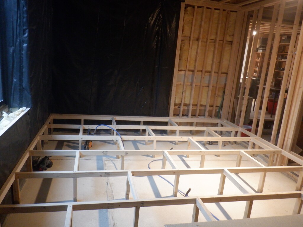
    Then we laid down six sheets of OSB boards to provide a temporary floor surface for us to move around more easily and we carried on nailing up more horizontal rails all the way around the four walls like before. This forms the Utility Channel structure that allows us to route wires and cables around plus also in and out of the room. A half a dozen conduits had to be inserted into the new Utility Channel to route the cabling around windows and doorways, plus also to provide a connection to various features like the shower mixer, the vanity unit and the toilet itself. A control box provision was also created near the room’s entrance and this section will contain the computer equipment and other electrical safety devices that this bedroom will need.
    Started On Building Bedroom Two plus Running Water Pipes Under Floor

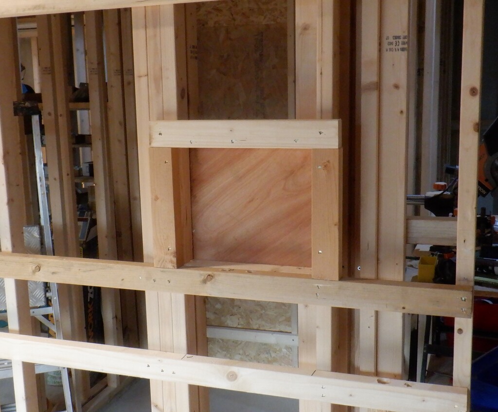
    Bedroom-2-Control-box-location


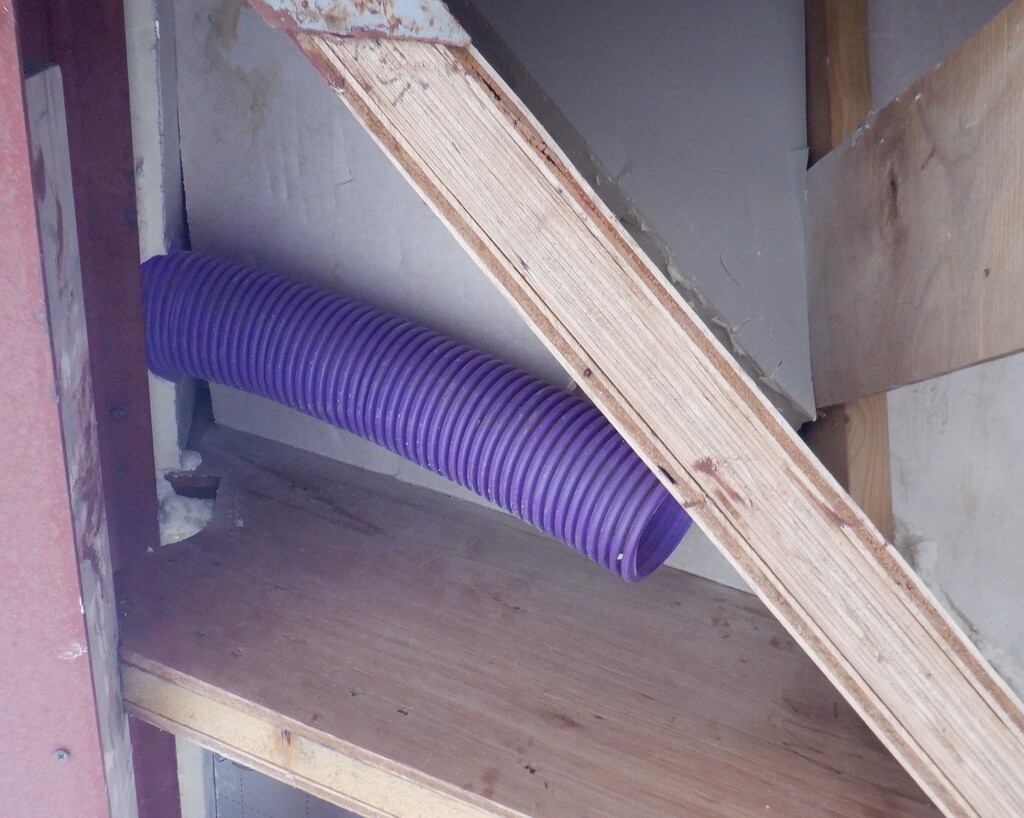
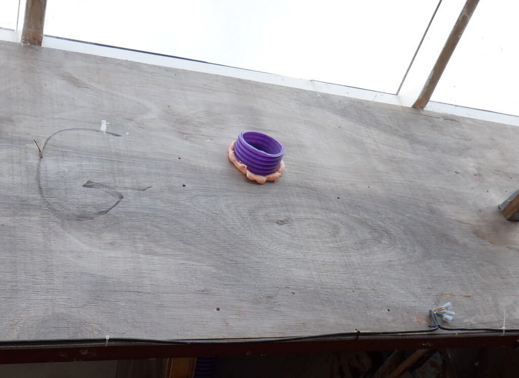
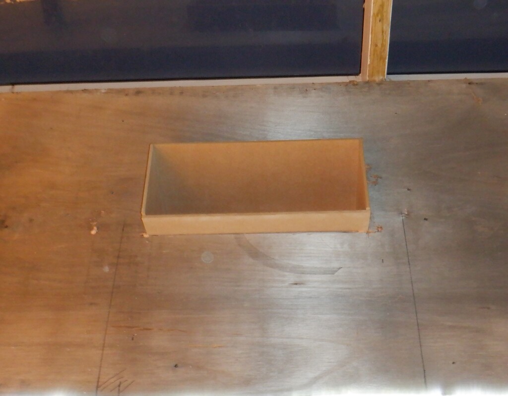
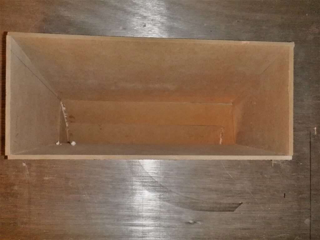
    The window’s sill was finished by creating a chamber underneath the window seat that will hold a place for the window blinds mechanism and possibly a secret storage location too. Another conduit was inserted so wires could travel in and out of the window seat chamber, to the Utility Channel.
    Started On Building Bedroom Two plus Running Water Pipes Under Floor

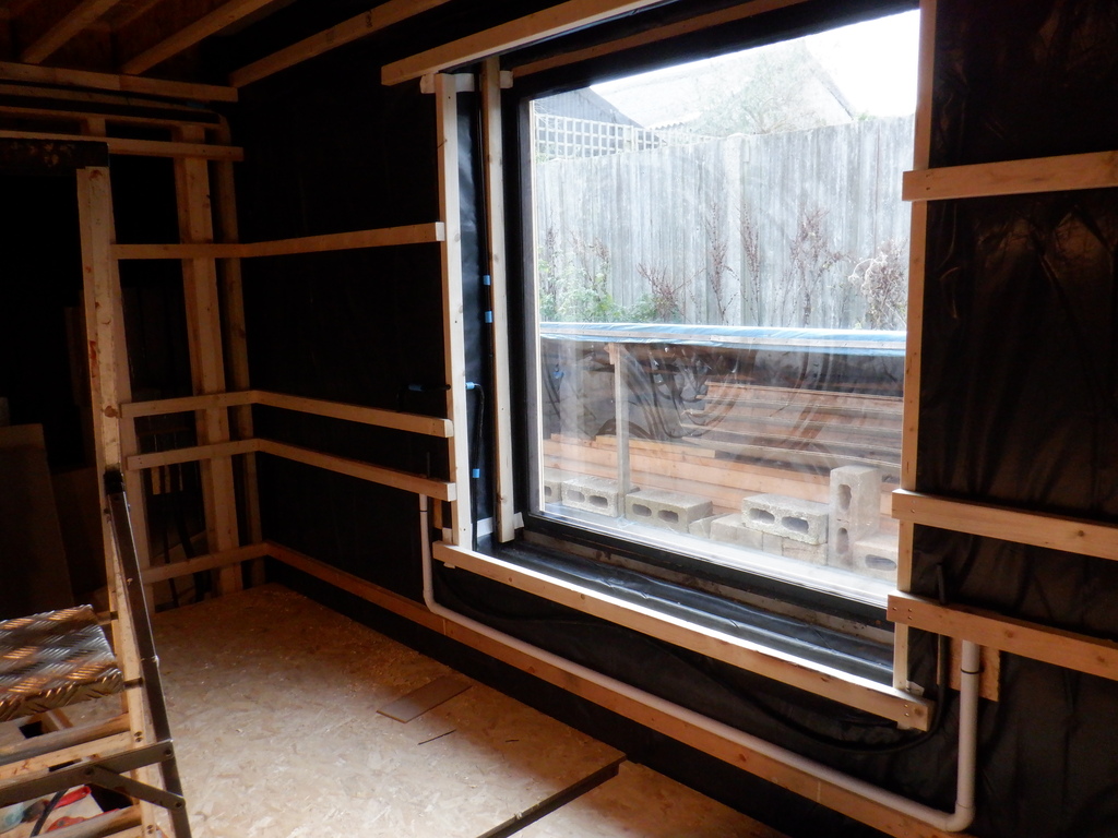
    Conduits-Bedroom-2-Window


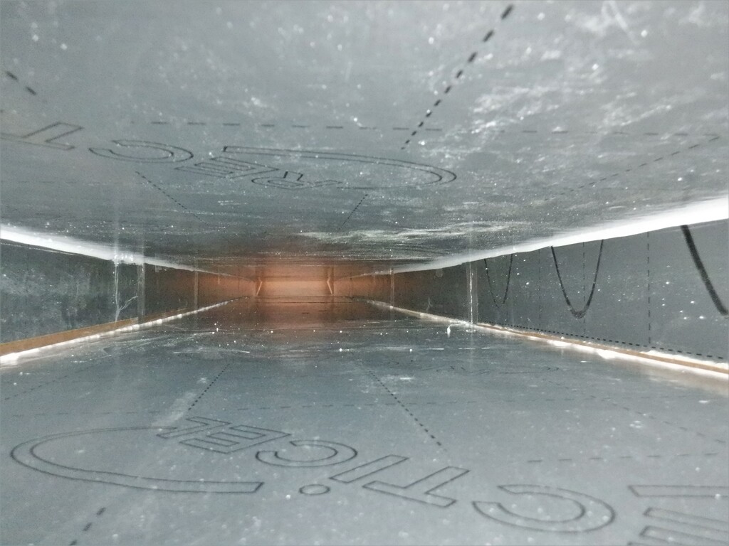
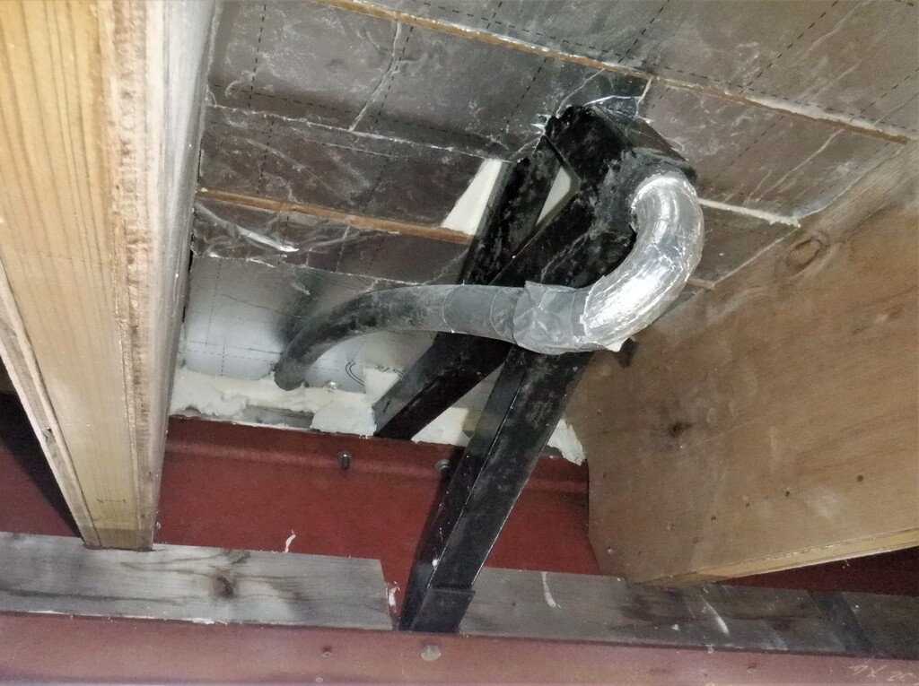
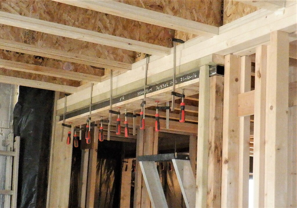
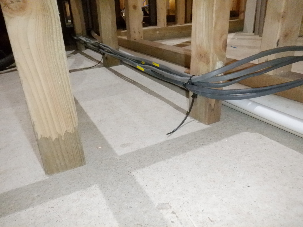
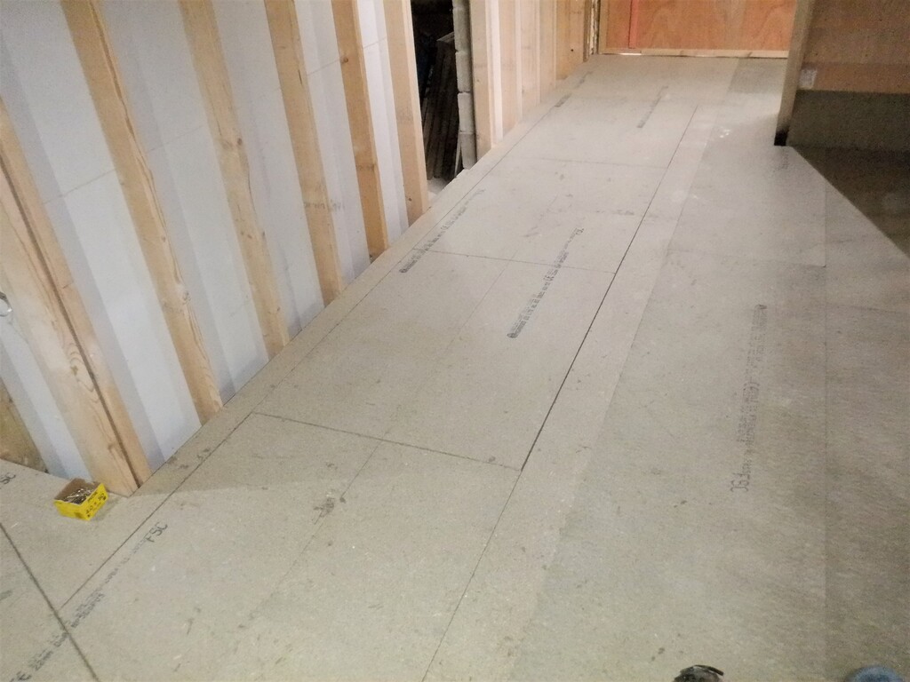
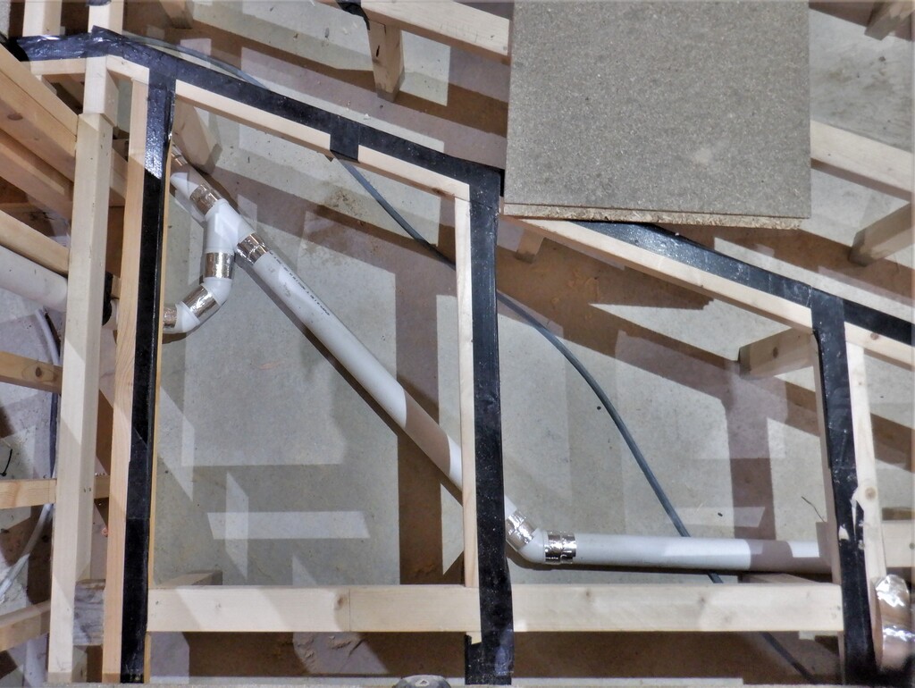
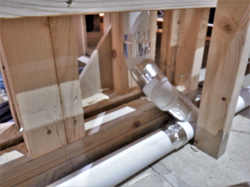
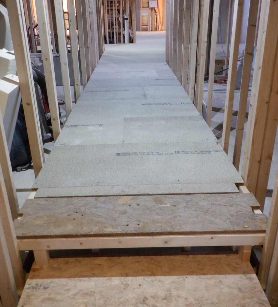
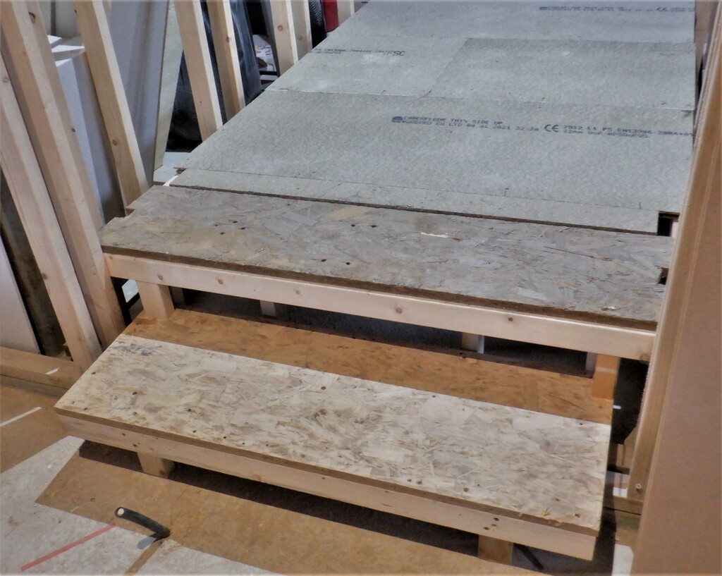
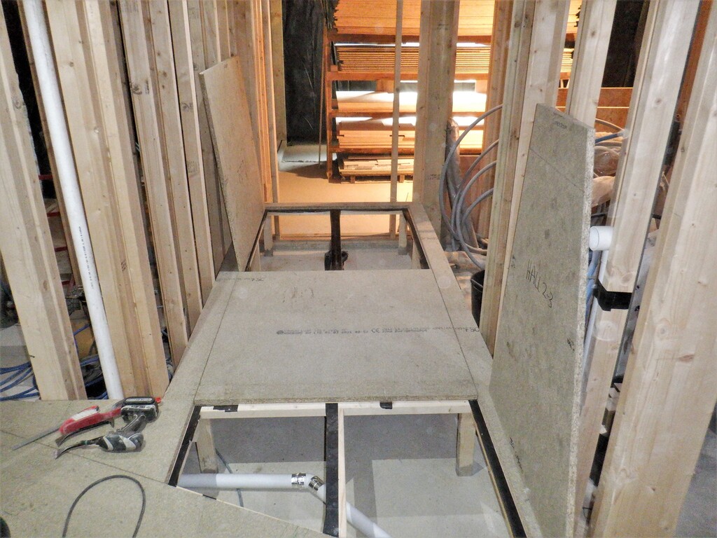
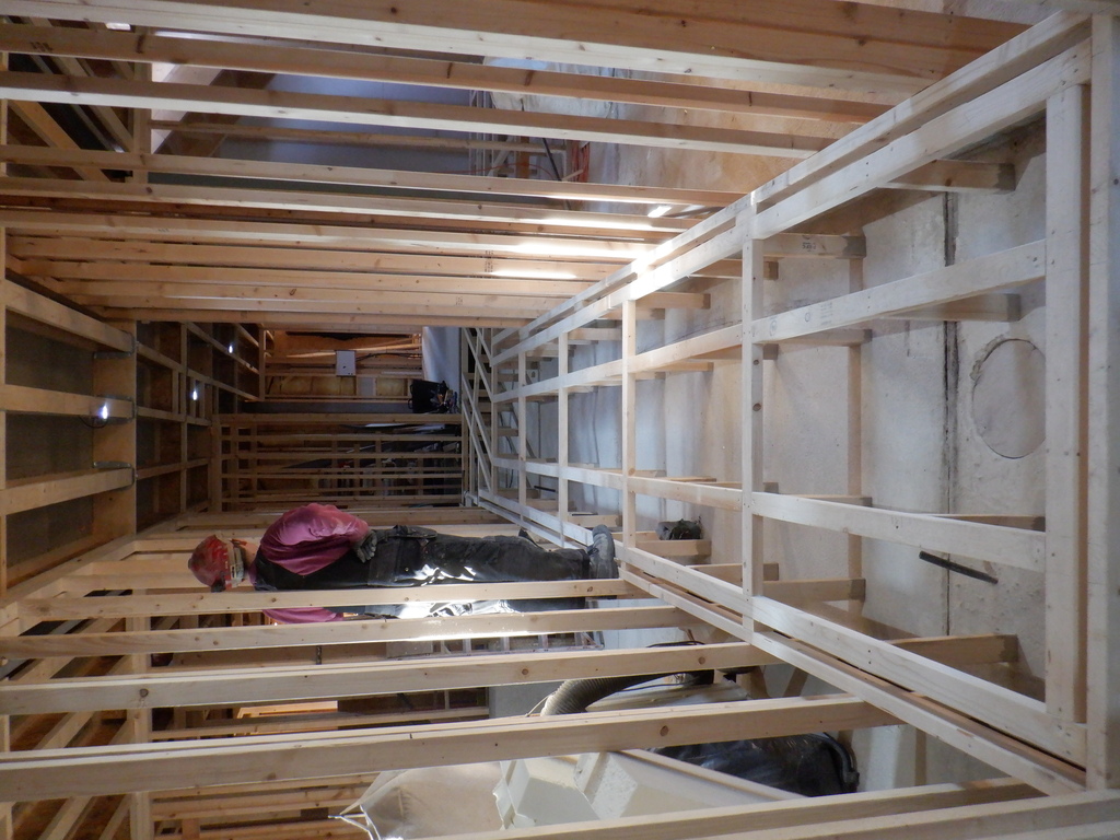
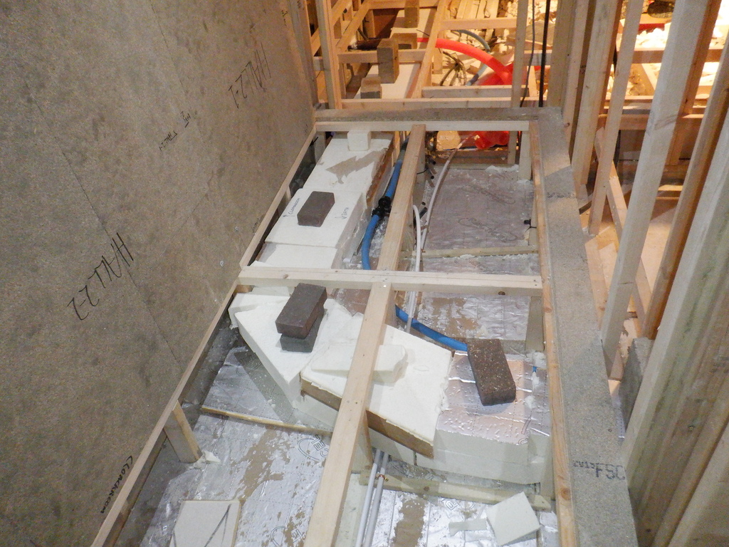
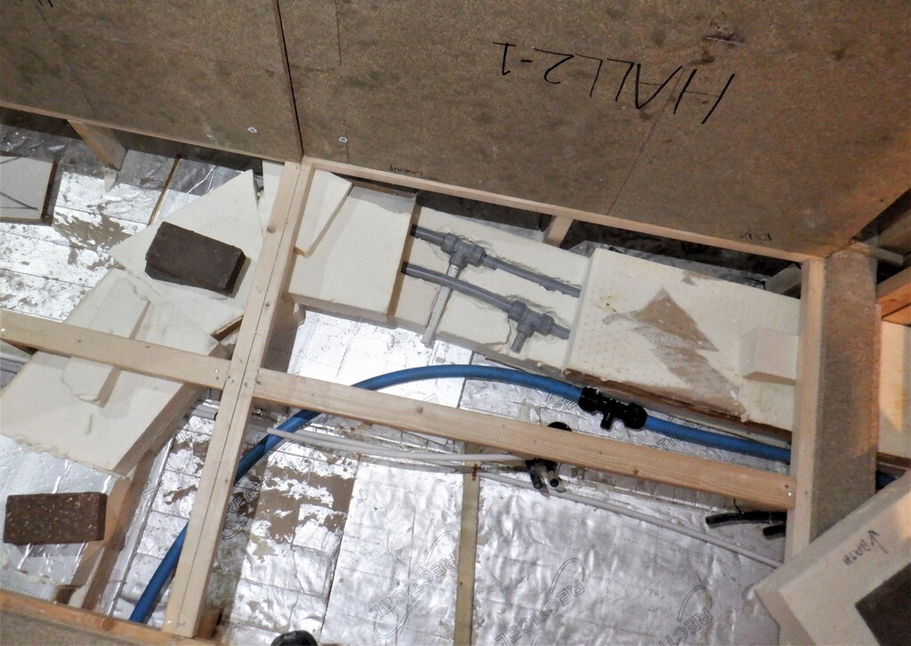
    The next job was the plumbing running along under the hallway flooring. We needed to route a couple of 15mm water pipes from the Energy Module situated under Bedroom Two and travel all the way back to the Equipment Cupboard in the Utility Room in a neat manner. We screwed a regular set of horizontal battens across the middle set of legs that will do a double role of holding up the air duct but also provide a mounting point to keep the collection of plastic pipes neat and tidy using cable ties pushed through a drilled hole in the batten.
    Started On Building Bedroom Two plus Running Water Pipes Under Floor

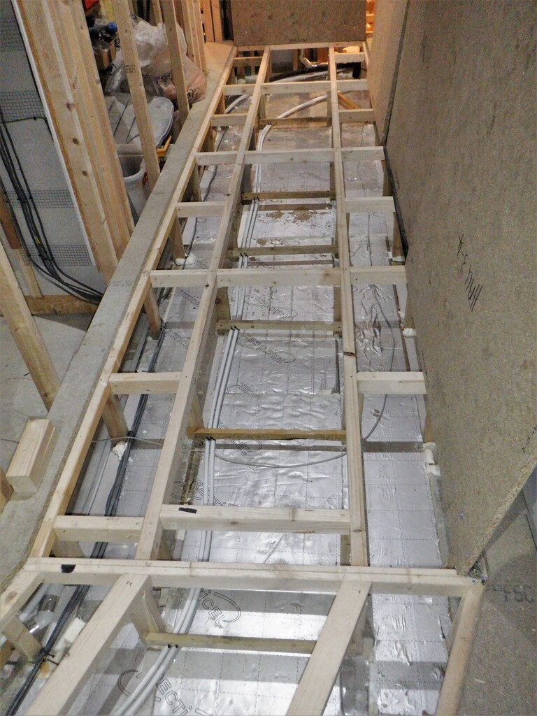
    Hall-12-Duct-plumbing-support-ties-1

    Started On Building Bedroom Two plus Running Water Pipes Under Floor

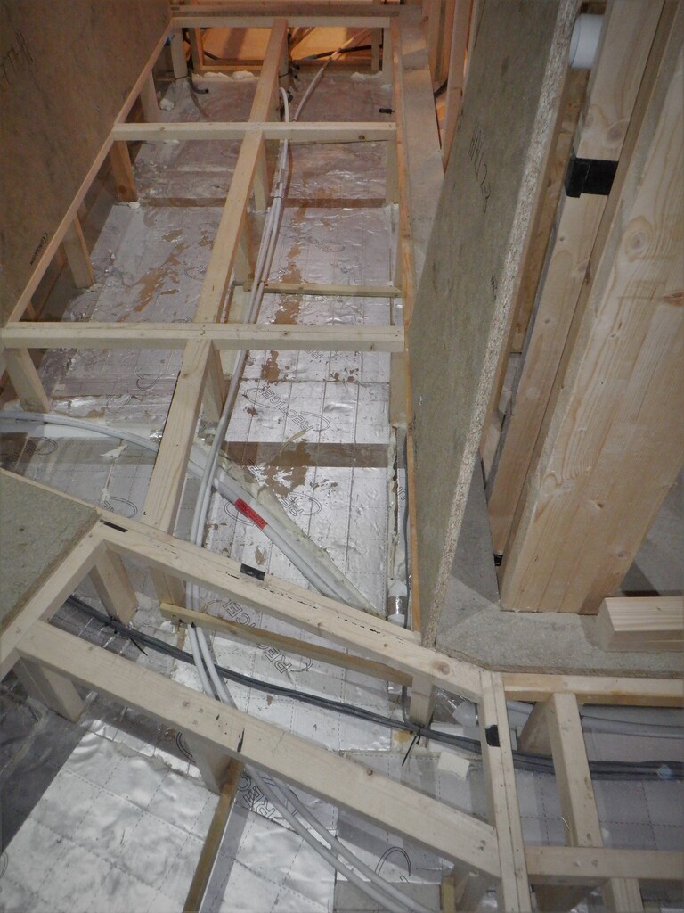
    Hall-12-Duct-plumbing-support-ties-2


    We continued in placing more conduits, this time under the flooring for things like the temperature sensors that surrounds the buried Energy Modules plus also a watering system for routing water to any hanging baskets from the gutters outside. We had to put in extra conduits from Bedroom Three to serve the ensuite because we had forgotten to make the connections when we were doing that bedroom earlier the year. Another conduit was laid in for our compressed air, to route it up to the top of the sliding door so it can power the movements of the doors. We put in a complete circuit of conduit around above the window and doors and this will contain the hearing loop wire to provide extra audio connections for deaf people. This circuit comes in and out of the control box.
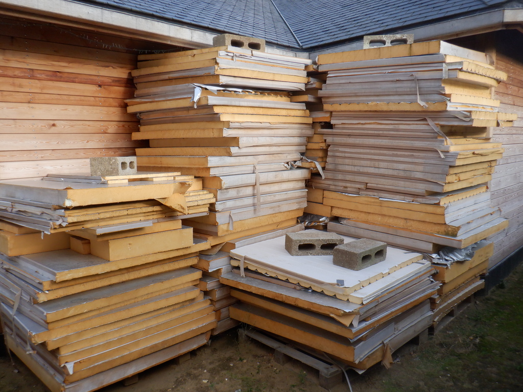
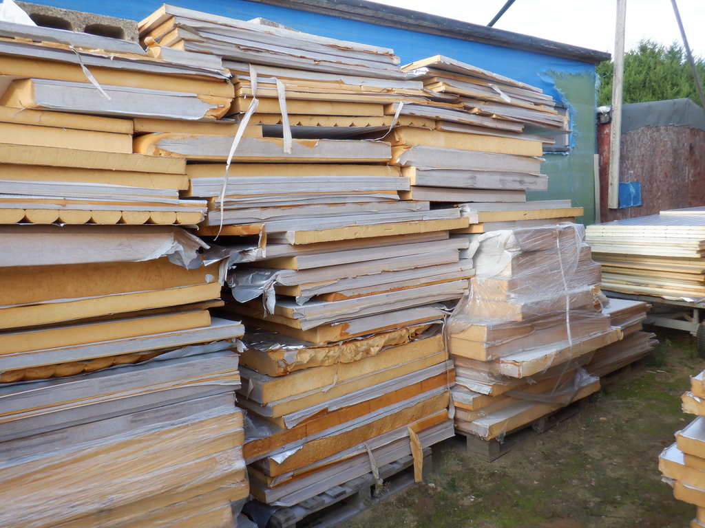
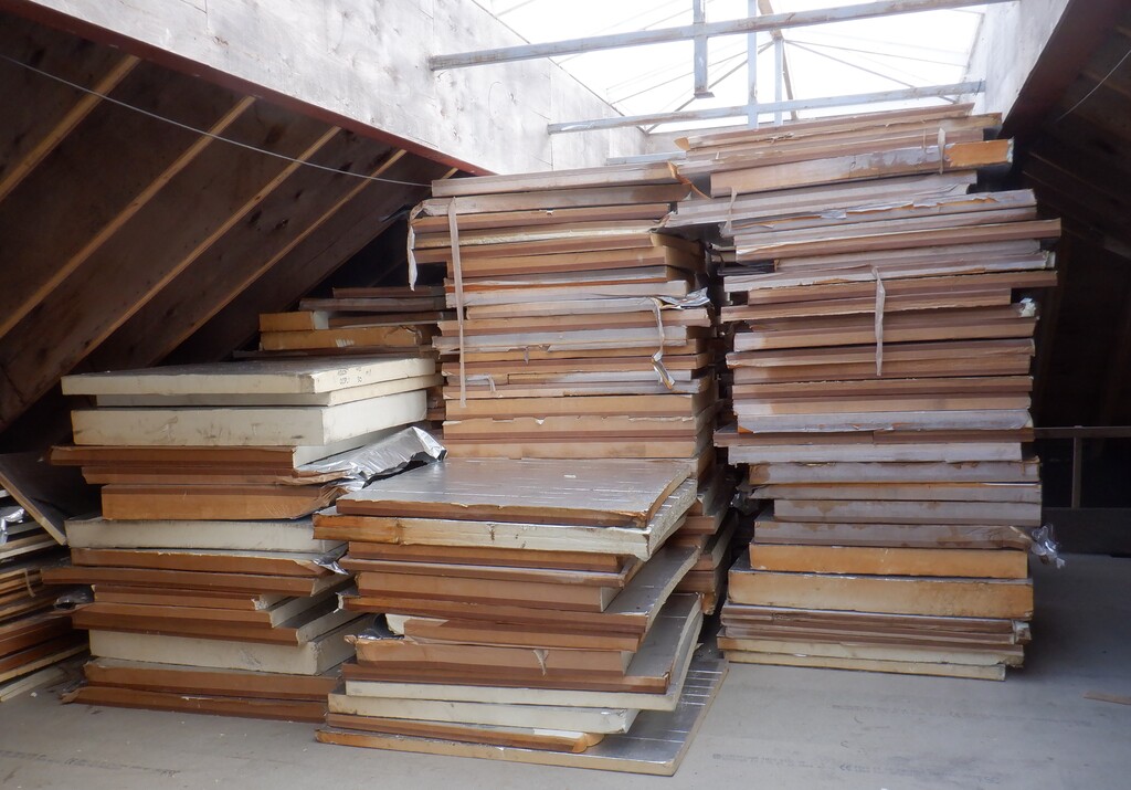
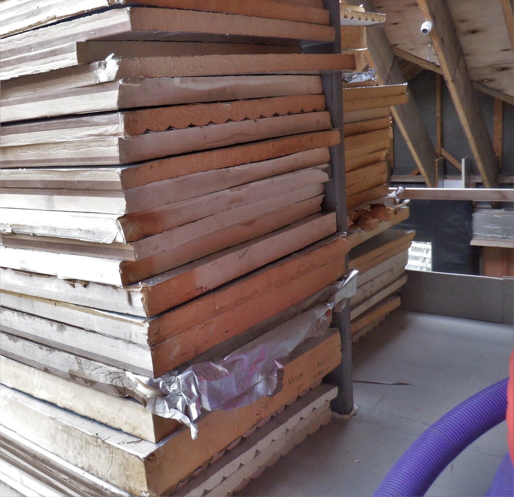
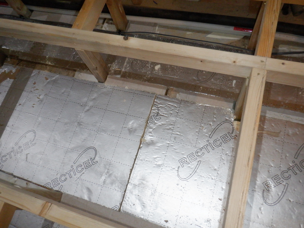
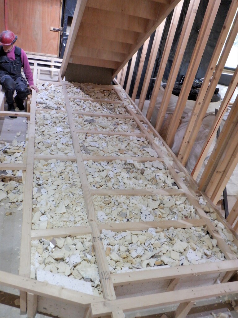
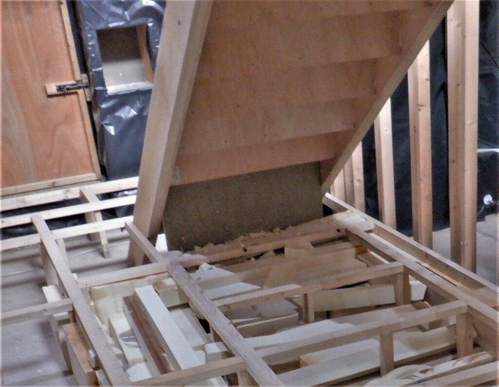
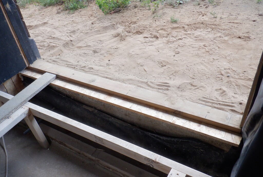
    Then the load of PU foam rubbish was brought in and laid down in the floor space, to provide insulation against the cold concrete, especially near the outside walls but also to provide some insulation against the buried Energy Module which will get warm during the summer and autumn months and we don’t want too much excess heat getting into the room.
    We managed to completely empty our large external “bag” of rubbish bits and pieces and we now have been able to collapse and tidy away the plastic tarpaulin we used to construct the temporary bag. The alcove, situated around the back of the house, outside the windows of Bedroom One and the Great Room is now all neat, ready for us to dig a hole to install a couple of electrical junction box plus also an external mains electric socket.
    Then we created four standard air dispersers, which were fixed to the bottom near the middle of each wall, then connected to flexible orange 50mm (the interior dimensions) twin-wall plastic conduit, going from each wall and back over to the doorway, ready for the main air splitter chamber.
    Started On Building Bedroom Two plus Running Water Pipes Under Floor

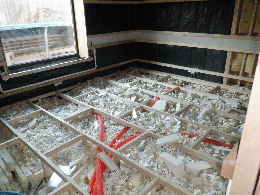
    Bedrrom-2-Floor-All-conduits-and-ducts-Insulation-1

    Started On Building Bedroom Two plus Running Water Pipes Under Floor

    Bedrrom-2-Floor-All-conduits-and-ducts-Insulation-2


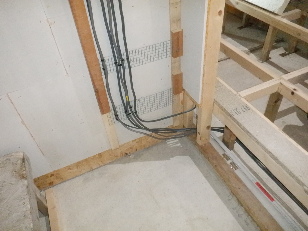
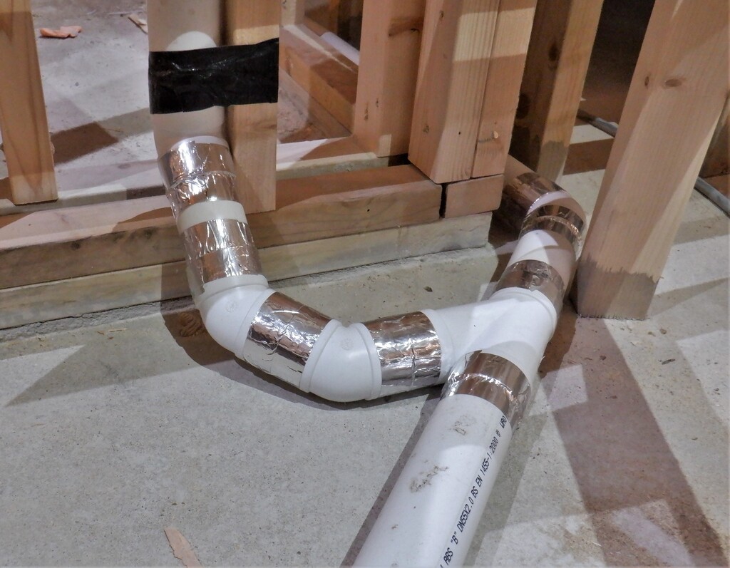
    The circulating hot water was next, to continue the twin lines of 28mm diameter water pipes coming from Bedroom Three, going across Ensuite Three, through the Bathroom, turning into Hallway Two and heading into Bedroom Two to arrive at the access chamber just outside Ensuite Two.
    But first, we needed to get the waste plumbing pipework sorted for Ensuite Three and the Bathroom so we installed a boss fitting to the sewage stack, right down at the bottom nearest to the concrete, to allow the maximum amount of liquid level drop coming from the various waste outputs like the basin and the shower plus also the bath too. The shower’s waste is the critical one because we wanted to install a heat recovery system to recycle the hot energy from the waste water and put as much of it back into the fresh clean water going to the shower. To achieve this, the module will need space and time to maximise the energy transfer from the waste water to the clean water, before the waste water flows out and down the sewage stack.
    So we put in a couple of 40mm waste pipes, with a gradient to make the water flow towards the sewage stack and got three connection points ready for future installations.
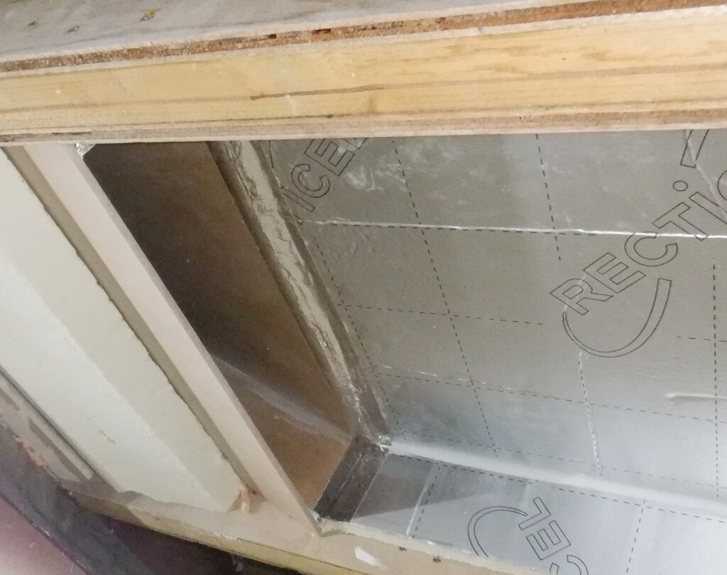
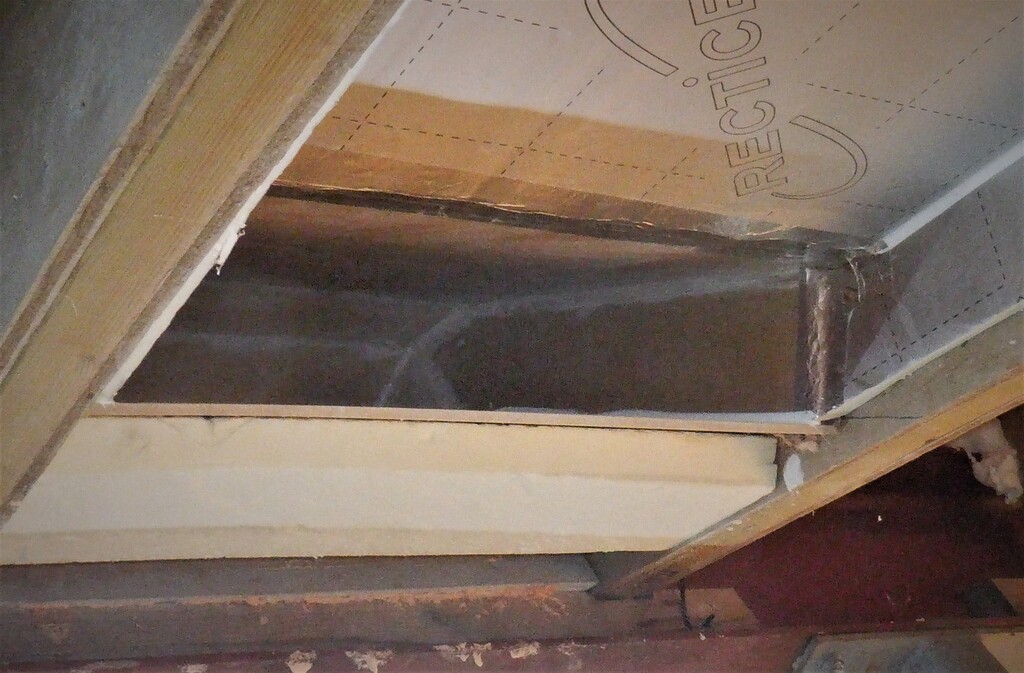
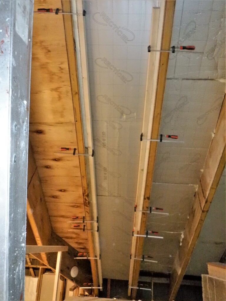
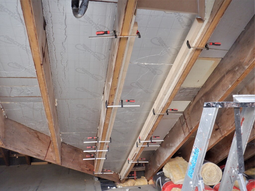
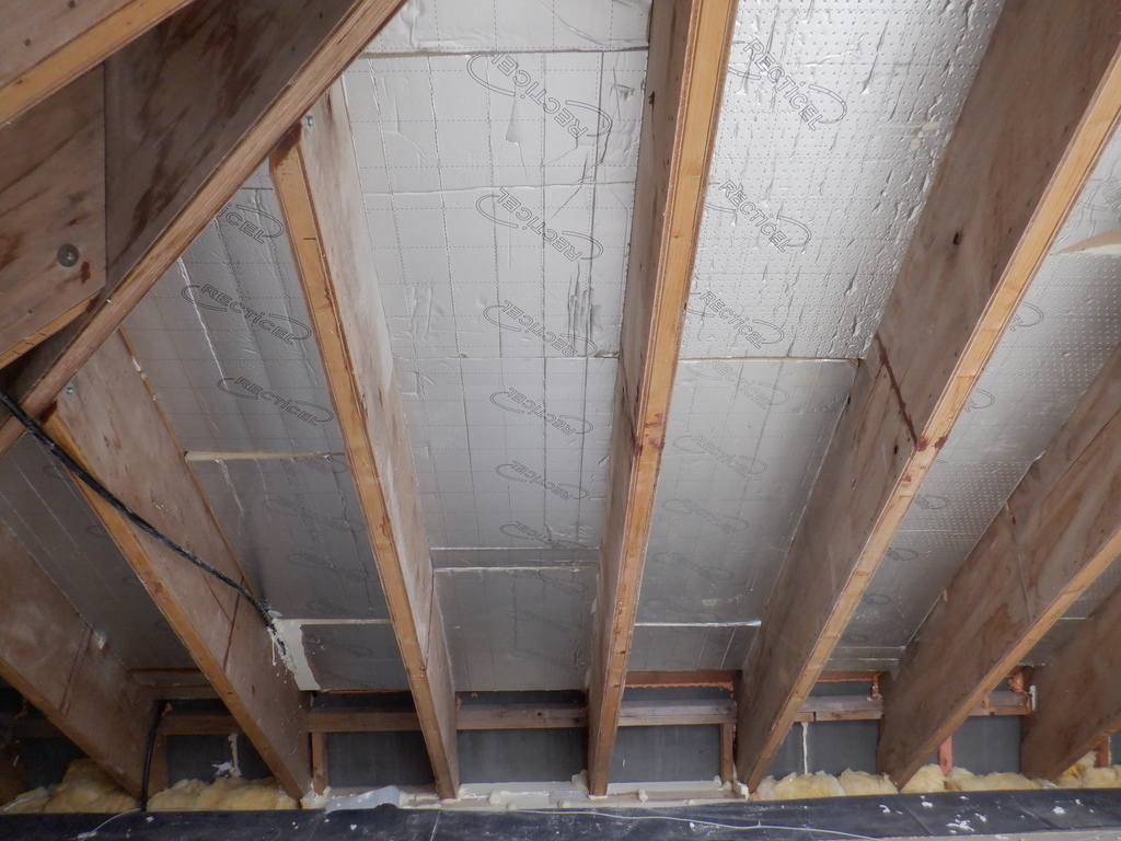
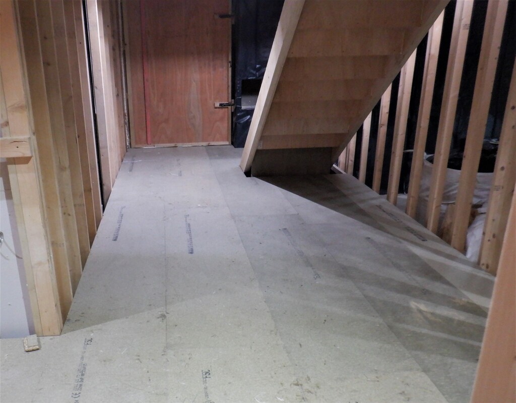
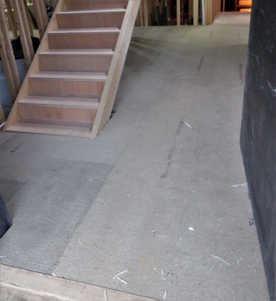
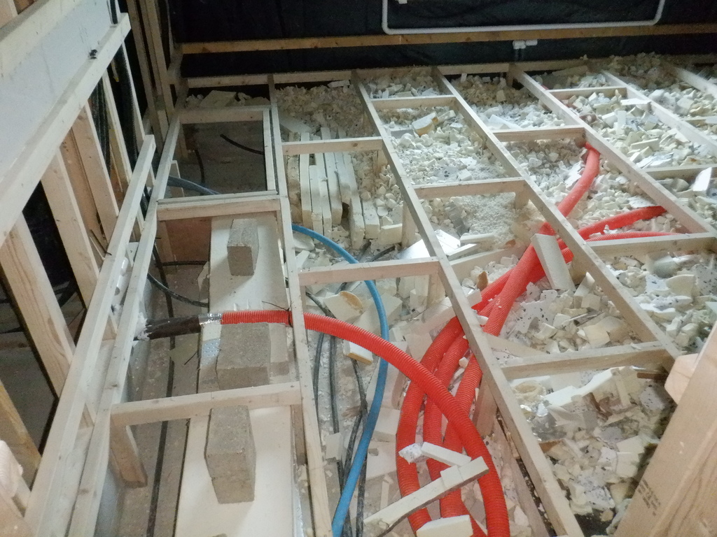
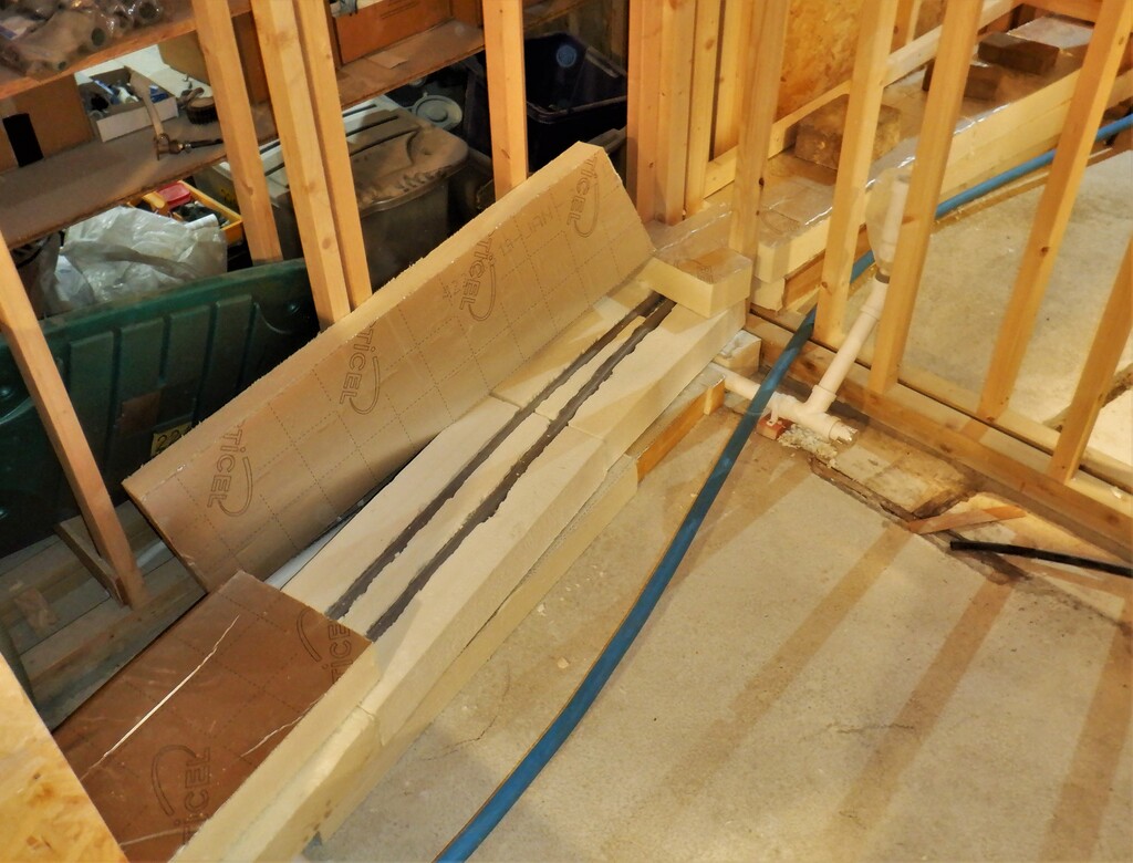
    After that, we laid down a layer of 90mm thick PU foam boards going across the Ensuite and the Bathroom, 250mm wide, following the path of the Hot water. On top is another layer of PU foam, this time 100mm thick which had two grooves sliced out to encapsulate the 28mm wide plastic plumbing pipes. The path is a straight line across the two rooms but also keeping tightly to one edge so to avoid the sunken bath tub itself, where the sloping ends will be. The second layer continued into the Hallway Two section, turning towards the next plumbing destination, the ensuite in Bedroom Two. The hallway section will have many different control modules and plumbing units, having to serve plenty of surrounding rooms like the Bathroom, the Cloakroom and even to the upstairs toilet and shower too. The 28mm pipes finally continued into Bedroom Two and currently terminates inside the service chamber outside Ensuite Two. The whole lot then had a third layer of more 100mm thick PU foam to cover the plastic pipes and insulate the hot water that will be circulating continuously, to minimise the time to get any warm water coming out a tap or shower. This is very similar to a traditional central heating system and its circulation hot water and using heat exchangers or radiators to “transfer” the heat into the clean cold water or fresh air.
    One of the last things we did before we closed down for Christmas was to run alongside the hot water, a cold water feed. This time we are using a bigger 32mm diameter polyethene pipe, a blue one, to provide the clean water to all the various outlets distributed around the house. It ran alongside the PU foam, following the same path and it also is currently terminates in the ensuite in Bedroom Two.
    Started On Building Bedroom Two plus Running Water Pipes Under Floor

    Waste-and-water-in-En-suite-3-Bathroom

    Started On Building Bedroom Two plus Running Water Pipes Under Floor

    Heating-pipes-turn-along-Hall-2-and-into-bedrrom-2

    Started On Building Bedroom Two plus Running Water Pipes Under Floor

    Hall-2-plumbing-zone

    Started On Building Bedroom Two plus Running Water Pipes Under Floor

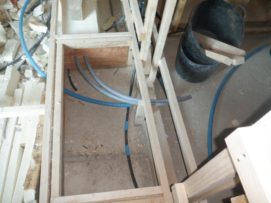
    Bedroom-2-En-suite-plumbing-access


    The next job when we restart in the new year, probably about the 2nd week of January after a couple weeks of holiday, is to make an air disperser unit and put in an extra electrical conduit beside the window to have ready a connection for automated curtains and lighting if we want to have such a thing.

  • Air Duct Created up in Skylight and Down Rafters

    We finished off the two air ducts we started last week. We put on the extra layer of MDF boards underneath to complete the downwards chute before it runs into the PU foam boards. We coated the MDF with several layers of acrylic varnish to seal the wood material against moisture and also sealed the joints with two-part resin wood filler, to smooth off the sharp boundaries and bends to reduce the air turbulences.

    Air Duct Created up in Skylight and Down Rafters

    DUct-through-steel-complete-1

    Air Duct Created up in Skylight and Down Rafters

    DUct-through-steel-complete-2


    The rafter had layers of PU foam boards inserted to a depth of 250mm, with a smooth surface exposed outwards. This forms one of the four sides of the ducting travelling inside the rafter, with the two narrow edge strips glued and positioned in place with long CLS pieces of timber while the glue dried.
    Air Duct Created up in Skylight and Down Rafters

    Duct-lining-glued-in-1

    Air Duct Created up in Skylight and Down Rafters

    Duct-lining-glued-in-2


    Finally, a lid was put on, a 25mm thick layer with its smooth surface facing inwards this time, creating the fourth side for the air to be transported downwards and into the main house ducts.
    Air Duct Created up in Skylight and Down Rafters

    A-view-inside-the-duct


    The next job was to drill a large circular hole through the Skylight to provide a 100mm diameter ducting, ready for servicing the upstairs toilet and shower room.
    Air Duct Created up in Skylight and Down Rafters

    Upstairs-bathroom-air-duct-1

    Air Duct Created up in Skylight and Down Rafters

    Upstairs-bathroom-air-duct-2


    We then had a big tidy up of all the rubbish we generated and moved things around to make them neat and tidy. We decided that we won’t continue with putting any more insulation boards up into more rafters because it is not really making any major difference to retaining the heat, the Skylight is still completely uninsulated and all the heat will escape that way. We will continue working on the Ground floor and continue in building the next room.

  • Roof Rafters Accessible from First Floor Has Some Insulation Inserted

    This week, we completed the task of inserting at least one layer of PU foam board up into the rafters that we can reach from the First Floor .. the other half of the building, along the back doing sections M, L, K, J and I.

    The task we thought we ought to do next is to make a couple of unusual air duct channels, to take the hot air out of the Skylight. We used the rafter space itself to encapsulate the air duct tubing so it is hidden and does not intrude into our living space. We had one down near the Great Room and the second location is right down at the other end of the Skylight where it squeezes through a narrow opening just before the hip section of the glass.

    We had to cut our way through the kerb and all its layers of material, removing everything down to the steel RSJ surface, making a rectangular shape hole but with a tapering top surface to guide the air downwards.
    We used 6mm MDF sheet material to create the liner for the chute, to go over the steel RSJ beams and bend downwards to the bottom of the rafters, where the air is then transported down using more smooth insulation boards and this travels down before sweeping sideways to join into the main air duct that will be built to run around the whole house.
    These MDF pieces were all glued in using our glue grade expanding PU spray foam, putting in lots of clamps to hold them in place while the glue sets.

    Roof Rafters Accessible from First Floor Has Some Insulation Inserted

    Skylight-duct-M-1

    Roof Rafters Accessible from First Floor Has Some Insulation Inserted

    Skylight-duct-M-2

    Roof Rafters Accessible from First Floor Has Some Insulation Inserted

    Skylight-duct-M-3


    The size of the first chute near the Great Room is approximately 500mm wide by 100mm high, with a slight squeezing as it travels over the RSJ but having a 50,000 square millimetres capacity is about half the total capacity of our main air ducting that the fan is designed to work with. It is that size because the skylight and the Great Room will be collecting a great deal of sunshine energy during those sunny days and we need to make sure we have the capacity to remove this hot air easily without struggling. It is so much cheaper to design in a high capacity air ventilation system in the first place, combined with our super-insulated roof and walls, would mean that we don’t need to burn large amount of electricity to run refrigerated air conditioning units to cool the house down. Invest the money in the insulation at the beginning, a fixed cost and avoid the running costs later on especially if the world is facing large temperature rises.
    Anyway, we did the second chute as well, with a similar design using MDF pieces but only 300mm wide by 100mm high, before spreading out to the full width of the rafter like before. We also put up more layers of foam boards up and down the rafters themselves.
    Roof Rafters Accessible from First Floor Has Some Insulation Inserted

    Skylight-Duct-I-1

    Roof Rafters Accessible from First Floor Has Some Insulation Inserted

    Skylight-Duct-I-2


    Another job we did was to drilled a conduit hole through the kerb at our ‘chimney’, to allow a 40mm conduit to connect to the bottom of the metal arm and vertical pole. The vertical pole has a 40mm conduit going up the inside and poking out the top, ready for the electrical connections to all the devices that will be mounted into and on the chimney when that is built later on.
    Roof Rafters Accessible from First Floor Has Some Insulation Inserted

    Chimney-conduit-passing-through-kerb


    That is about it for this week, we will finish off those two special ducts, plus one more that is needed for the upstairs toilet and shower room, which also has to come over the steel RSJ but we only need a simple 100mm round hole to let the flexible air ducting through. The other job to finish off is dealing with the last huge pile of PU foam boards which we will slice up and insert in places up in the roof rafters, just to get rid of them.

  • Installing Insulation Into Roof

    We had a week of slicing and pushing loads of PU insulation foam boards up into the rafters! We carried on with the task we started last week where we wanted to get rid of all the random collection of 2nd grade of expanded polyurethane foam boards we acquired very cheaply, slice it up and put at least one layer in every single rafter we could access from the First Floor. We wanted to take the opportunity of the cooler weather to get this done and also have some measure of success when we needed to heat up the whole house when we will be working through the winter months. We were half way through covering up the gable section above the Front door last week so we got the second layer of 25mm thick boards and got that finished, bringing the total thickness to 50mm. This is only the start and eventually, we want to put in at least 300mm of some form of insulation, finishing off with glass wool for the added fire protection that will afford us.
    We then proceeded to start slicing up the next bunch of boards into a collection of 550mm wide pieces and sorted into similar thicknesses. They ranged from a thinly 50mm to a very fat 150mm whoppers, with most of them being in the range of 60mm to 80mm.

    Installing Insulation Into Roof

    Pile-of-sliced-insulation


    We started in the roof area near our slicing machine, the “H” section that goes along the north side of the house, that is over Bedroom Three and the Utility Room. Some of the gaps between the rafters were tight and some were loose for the foam pieces, not by much but sometimes it was very difficult to jam in the board so we had to cut a slight angle off the long edge so it reduces the friction a little, enough for us to thump the board into place. We started at the bottom of the rafters but made sure we had a cleared gap of about 200mm, ready to be filled up with more glass wool for that extra fire protection, especially since all the roof rafters all have projecting Eves and we didn’t want any flames the chance of an easy route up our roof.
    The top of the rafters terminates either at the Skylight and the steel RSJ or stops with an angle on a diagonal hip or valley beam. The Skylight needed to have a vertical layer of foam board inserted above the RSJs to make it easier when we come along with the layers and layers of foam boards in the rafters so we did that little job all the way around the whole Skylight in one go first. We cut lots of 60mm thick boards into 550mm wide and then carefully sliced at 200mm an angled cut using our jigsaw positioned at the 32degree angle to cut a sloping top.
    Installing Insulation Into Roof

    Pieces-for-skylight-kerb


    Anyway, we carried on inserting pieces of foam in along the H section, getting right down into the corner with the I roof and then went back to carry on the other direction to cover up along over the Utility Room and the Side door porch extension. We turned the corner and then went along the E section, around the next corner to do the C section which includes the the main ridge beam going out over the Front door and its extension.
    Installing Insulation Into Roof

    Insulation-in-H

    Installing Insulation Into Roof

    Insulation-in-G

    Installing Insulation Into Roof

    Insulation-in-D


    Next was the other side, the B section that goes over the staircase and turn onto the A section that goes over the Kitchen and towards the Great room. The stairs was a bit tricky because of a somewhat large hole in the First Floor but we handled that problem by laying out a dozen pieces of CLS timber and laid four partial sheets of plywood and OSB material so we could stand on it and climb our ladders. There was only two rafters to complete here so it didn’t take too long.
    We finished the week doing the A section, right up to the edge of the First Floor and the Gallery but couldn’t go any further. The Great Room will have to be tackled at another time because we will have to build and assemble some form of work platform all around the room so we could work up in the rafters and also put on the finishing plasterboard sheet materials to form the ceiling.
    So having completed this A section as far as we could, we could see that we have completed over half of the rafters and we used just over half the stacks of foam boards we got piled up on the Gallery so we should have enough to finish the job if we are lucky.
    Installing Insulation Into Roof

    Insulation-in-A

    Installing Insulation Into Roof

    Insulation-Piles-at-end-of-week


    We will carry on doing that next week and should get it finished by the end of the week. Then we can return to building the next room, installing the utility pipes and conduits etc.

  • Sliding Door Frames Installed and Started on Insulation In Roof Rafters

    Among several interruptions during this week’s work, we got on with installing new framework for two sliding doors for our stand-alone Bathroom as well as for Ensuite Two. Both of these rooms are going to have two half sliding doors, built into the body of the walls themselves (pocket), not exposed, mounted on the surface. It will be so much nicer to have our doors disappearing into the fabric of the walls, to keep them clean and much neater too. Our room doorways right across the whole house are going to be a standard 800mm wide, some 32inches wide which is wider than most normal doorways. The Side and Front doors will be 1000m or 39inches wide. Of course, some of this space will be required to hold the finishing oak pretty framing itself plus also some doorways are the more traditional rotating door type designs and this will reduce the gap a little bit. To enable the frame to be installed we had to glue a piece of 18mm OSB to the underside of the steel lintel over the doorways and then install the CLS posts in the right direction and position to hold the doors.

    Sliding Door Frames Installed and Started on Insulation In Roof Rafters

    OSB-glued-to-lintel

    Sliding Door Frames Installed and Started on Insulation In Roof Rafters

    Door-framing-for-bathroom


    Also during the week, we took each opportunity of dry sunny weather to bring in all our remaining random heap of PU foam boards and dumped the whole lot upstairs, so we can get on with installing at least one layer of foam board up into the roof rafters as the weather is getting cooler. We calculated that we have an estimated 170 sheets of various thicknesses from 50mm to 150mm, which each measuring a rough 1.2metres by 1.1metres, will give us a coverage somewhere in the range of 180 square metres. We would be able to cover about two thirds of our roof space with “some” insulating foam board at various thicknesses. Better than nothing at all. But it does mean that we will need to order another duplicate load of seconded PU boards again in the new year to get the required level of insulation in our roof we want, to achieve our super insulated goals.
    Sliding Door Frames Installed and Started on Insulation In Roof Rafters

    The-Remaining-Piles-of-Insulation-1

    Sliding Door Frames Installed and Started on Insulation In Roof Rafters

    The-Remaining-Piles-of-Insulation-2

    Sliding Door Frames Installed and Started on Insulation In Roof Rafters

    All-remaining-insulation-moved-upstairs-1

    Sliding Door Frames Installed and Started on Insulation In Roof Rafters

    All-remaining-insulation-moved-upstairs-2


    So we started on doing the two gable ends of the roof, the one over the Side door and the other over the Front door. We needed to use our 25mm thick boards to build up past the various battens we have on the walls holding the cement panels and the external larch cladding. It was a bit fiddly but it has to be done one day or another.
    Sliding Door Frames Installed and Started on Insulation In Roof Rafters

    First-layer-of-insulation-in-Front-door-gable

    Sliding Door Frames Installed and Started on Insulation In Roof Rafters

    Two-layers-in-the-side-door-gable


    Another job we tackled was to move the entire heap of wooden sheet material off our stack which is living in Bedroom Two, sitting on the concrete floor. It has been there for several years being very useful and accessible for our sheet material but now we need to get on with building Bedroom Two and hence why we did this heavy task! The stacking shelves have been unscrewed and is now in a collapsed heap waiting to be moved out next week!
    Sliding Door Frames Installed and Started on Insulation In Roof Rafters

    Sheet-goods-stored-in-Bedroom-2

    Sliding Door Frames Installed and Started on Insulation In Roof Rafters

    Colapsed-storage-rack


    Next week, we will continue installing more PU insulation boards upstairs in among the rafters but also start looking at building the flooring for Bedroom Two and getting the permanent pipes and conduits installed before laying down the floorboards.

  • Hallway Cavities Insulated and Mains Electric Installed

    The week was spent installing a layer of insulation inside the cavity under the hall’s flooring. We wanted to make sure that we don’t have too much leakage of valuable house energy, especially we will have our main air duct running in this cavity to supply fresh and warm air to all our rooms. So we took all the thin insulation boards that measured 50mm or 60mm thick and sliced them up into various widths to fit between the leg supports. This took a few days as you had to cut each piece to fit around the legs.
    We completed all the four hallway sections and glued them into place with spray PU foam.

    Hallway Cavities Insulated and Mains Electric Installed

    Jigsaw-of-Insulation-laid-in-halls-1

    Hallway Cavities Insulated and Mains Electric Installed

    Jigsaw-of-Insulation-laid-in-halls-2


    The next little job was to install mains electric cables, using twin and earth 2.5mm solid copper wires and ran them from the Tech Cupboard and its new consumer switch unit. We screwed little cable tie saddles on each of the legs and grouped together a bunch that are going off in various directions. We laid in cables to go to the Great Room, the Kitchen, then to Bedroom One, around the corner to Bedroom Two and finally to Bedroom Three. At the end of each cable  we installed a double switched socket (the Great room has already several sockets so we carried the cabling across the room to those, plus also Bedroom Three also had its collection of sockets already installed too) so we could plug in local piece of equipment without having to run our extension reel everywhere. We also sent one cable upstairs through the ceiling of the Tech Cupboard and mounted another double socket on the metal leg to serve the First Floor. The cables were then neatly connected to the appropriate switches in the switch panel.

    Hallway Cavities Insulated and Mains Electric Installed

    Cables-running-off-to-rooms

    Hallway Cavities Insulated and Mains Electric Installed

    Cables-enter-cupboard-and-are-routed-up-the-wall

    Hallway Cavities Insulated and Mains Electric Installed

    Power-to-each-room-neatly-terminated-in-the-switch-panel


    It doesn’t seems that we have done a lot this week, which is true because Shaun is still recovering from his eye operation but hopefully, things will get back to normal soon.

  • Started on Technology cupboard and Electrical panel.

    Stephen wanted a solo project whilst Shaun in resting, so he started on the Tech cupboard.
    First the two walls next to the bathroom and Storage cupboard where boarded with OSB (using up a lot of small pieces to make solo handling easier and using up the accumulated offcuts). Then Fermacell was stapled and glued up on the wall next the storage cupboard. This was enough to start working on the main Electricity switch panel (consumer unit).
    The panel was mounted about 1.2m above the floor and two cable trunks were constructed to manage the cables going down under the floors and up to the first floor. Then the 16mm² supply wires were pushed though the duct to the utility room, they were then connected to the main switch on the panel and the distribution block in the utility.

    All the switches were installed in the panel and all the fixed internal wiring was installed. Labels have been added to RCBO neutrals to help with testing.

    Started on Technology cupboard and Electrical panel.

    Tech-Cupboard-Switch-Panel-closed

    Started on Technology cupboard and Electrical panel.

    Tech-Cupboard-Switch-Panel-open

    Front-panel-circuit-labels

    Front-panel-circuit-labels

    Started on Technology cupboard and Electrical panel.

    RCBO-Neutrals-labeled


    Tech Cupboard Panel circuits

    Kitchen sockets RCD ring Shared RCD
    Hob RCD radial Shared RCD
    Ovens RCD radial Shared RCD
    Great room Sockets RCBO radial
    Conservatory Sockets RCBO radial
    Bed 1 Sockets RCBO radial
    Bed 2 Sockets RCBO radial
    Bed 3 Sockets RCBO radial
    Entertainment Sockets RCBO radial
    Tech cupboard 1 Non RCD radial Computers & backup DC
    Tech cupboard 2 Non RCD radial Primary DC PSUs
    Work 1 Sockets RCBO radial
    Work 2 Sockets RCBO radial
    Work 3 Sockets RCBO radial General use
    Work 3 Special Sockets Non RCD radial For Experimental use

    Tech Panel also has a Surge Protection Device fitted.


  • Hall floor hatches completed

    This week we finished cutting hatches into the hall floors on Monday and Tuesday.

    Hall floor hatches completed

    Hall-1-Hatches

    Hall floor hatches completed

    Front-door-hall-hatches

    Hall floor hatches completed

    Hall-3-Hatches-cut


    Then we needed a way of lifting the panels easily. So we drilled a hole 100mm diagonally in from each corner and inserted a ‘Pronged T Nut’ into each hole from below, then we could use a bolt with a T piece as a lifting handle.
    Hall floor hatches completed

    T-Nut-inserted-from-below

    Hall floor hatches completed

    Hatch-lifting-Handles


    This completes the hall flooring.

  • Floorboards Laid for all Hallways

    For this rather truncated week of work, we resumed the task of laying down the floorboards after a week of building the framework. One of the first things we did was to put in a load of insulation bits and pieces from our giant bag of “rubbish” we got outside into the area under the stairs. We also screwed a left-over piece of floorboard and put it vertically on the back of the 2nd step of our staircase and this will become the base of our control board for the stair-lift mechanism.

    Floorboards Laid for all Hallways

    Under-stairs-with-insulation-strips

    Floorboards Laid for all Hallways

    Under-stairs-filled-with-foam-scraps

    Floorboards Laid for all Hallways

    Panel-for-stairlift-controls


    We then installed more vacuum cleaner piping across the central cross hall with connections for a cleaning point and the Hall 2 side of the Tech cupboard and a T connection going upstairs.
    Floorboards Laid for all Hallways

    Vacuum-ducting-hall-crossways

    Floorboards Laid for all Hallways

    Vacuum-duct-for-hall-crsossway-point

    Floorboards Laid for all Hallways

    Vacuum-duct-going-upstairs


    The other thing we did was to sort out the front door. It was built way back before we had the new flooring so it is too low. We simply just sliced off a chunk of material using our wiggle saw after noticing where the new floorboards will be etc. Then we had to fix down a fresh new door sill (there wasn’t one there before) using another left-over piece of 2by4 pine timber and along with a sheet of 10mm cement board, we screwed and sealed both items down into the concrete blocks underneath. This is only temporary until we are ready to build and install the proper door structure later on, using proper Oak timber.
    Floorboards Laid for all Hallways

    Temporary-front-door-sill


    Then we carried on putting down lots of floorboards, starting where we left off, in both Hall Two and Hall Three (going off to Bedroom Two and Three respectively) and we were very lucky to discover that these two “arms” were right angles to each other so the tongue and groove slotted together very nicely. Going down the side of the Entertainment Room only needed to slice off a very small narrow strip which was also lucky and arrived at the front door. We soon got the crossroad all covered up and then cut around the staircase too. finally, we went down Hall One towards the Great Room, going past Bedroom 1 and the Kitchen. It all went very nicely in the end and to finish off, we made a wide step at the entrance to the Great room to make it easier for anyone stepping off the new hall floor surface (being 400mm- 16inches high) especially if we are carrying large or heavy material in and out of the Great room.
    Floorboards Laid for all Hallways

    Hall-cross-way

    Floorboards Laid for all Hallways

    Front-door-hall-1

    Floorboards Laid for all Hallways

    Front-door-hall-2

    Hall 1 from Great room

    Hall 1 from Great room

    Floorboards Laid for all Hallways

    Step-down-to-Great-room


    We had finished at end of Thursday. Friday was lost to Shaun having a minor eye operation and Stephen resuming doing the Grapevine Talking newspaper after 18 months.
    On Saturday Stephen started slicing the nice solid floor boards up into Ribbons! Well the ribbons are about 1m wide and are cut into rectangles as well. These are the liftable hatches to give access to the utility’s under the hall floors. All the ribbons have been cut and cutting of the hatches has started with Hall 2 and Cross hall hatches being cut.
    Floorboards Laid for all Hallways

    Hall-2-lifting-panels-cut

    Floorboards Laid for all Hallways

    Cross-Hall-lifting-panels-cut


    There will couple of slower days next week because Shaun needs to keep quiet and recover from his Op.

  • Finished Framework for Hallway Flooring

    This week (apart from one day on Friday lost due to other commitments) was spent constructing the complicated framework for supporting the remaining Hallways, going up to the Great room, the crossroads and the bigger section under the stairs and up to the Front door.
    One of the tasks we had to do first before all that was done was to dismantle our large 8foot ramp that have been serving a very useful unction when we needed to bring in a trolley load of 8foot by 4foot sheet material or a pile of floorboards. It has been there for a few years and now it is gone, the pieces recycled for other jobs around the house.
    The assembly of the framework was a slow process of setting the main outer rails down a section, supporting it with clamps while then progressing bit by bit using our green laser line generator to mark where each leg needed to be sliced so it can fit under the rail just about right, to avoid lifting it up or being too short and missing the concrete floor entirely, which meant repeatedly going back to our chop saw and nipping off very thin slices. We even took to grinding the concrete floor itself to help settle these legs in place. There are dozens and dozens of these blessed .. I mean lovely legs, doing a vital job of holding up the flooring for all our hallways.
    One of the section that we thought didn’t need liftable panels was the route up to the Front door area but we realised that we couldn’t achieve that goal because we don’t have any pipes or air ducts ready to be permanently installed so we had to create a narrower lifting up section to allow us to install the necessary utility pipes etc, up to the front door, to serve the Entertainment room, the Front door itself and the stair lift mechanism too.
    We completed the framework under the stairs which will holds various storage segments, some will pull out on wheels and a larger section for walking in. We had to put down temporary framework around the bottom of the staircase where the stair-lift mechanism will reside but again, we didn’t have any of the pieces that will make up the platform module or the pulling chain and cog wheels. We will have to come back to this area and unscrew the floorboards later on.
    There was one sticking up conduit, coming out of the concrete, it is one of our temperature probes for monitoring the soil temperature between our energy modules buried underground, so we connected additional 20mm plastic conduit and routed it around to where the main gathering of the access point to this large Energy module situated under the Kitchen and Bedroom One.

    Finished Framework for Hallway Flooring

    Hall-floor-framing-1

    Finished Framework for Hallway Flooring

    Hall-floor-framing-2

    Finished Framework for Hallway Flooring

    Hall-floor-framing-3

    Finished Framework for Hallway Flooring

    Hall-floor-framing-4

    Finished Framework for Hallway Flooring

    Hall-floor-framing-5


    One of the consequences of putting down the framework, right up to the Front door area, is that we cannot open the temporary front door! It is too tall, or rather too deep. We will have to slice off a small piece off the bottom of the door before we can open it again!
    That will be one of next week’s tasks, as well as filling in some of the area with insulation and then proceed to cover all this lovely framework with floorboards. Hurray!