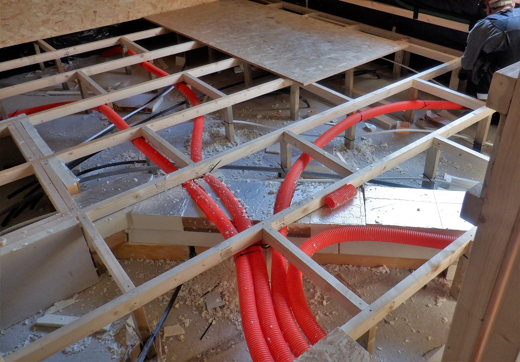
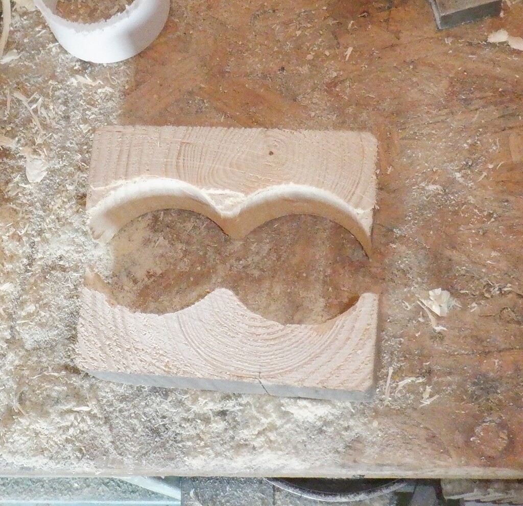
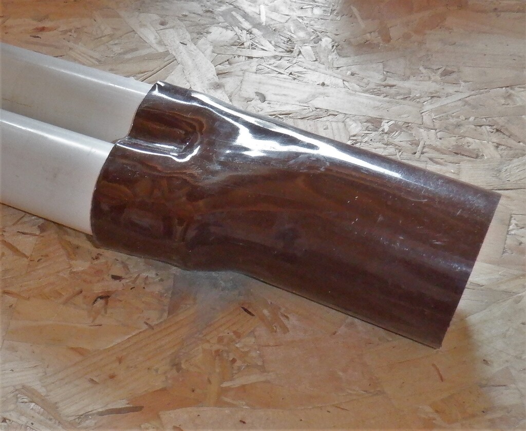
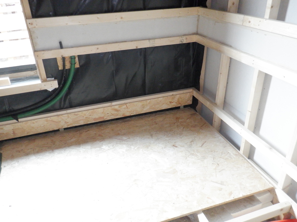
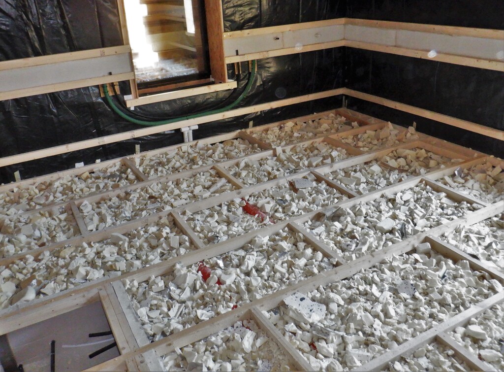
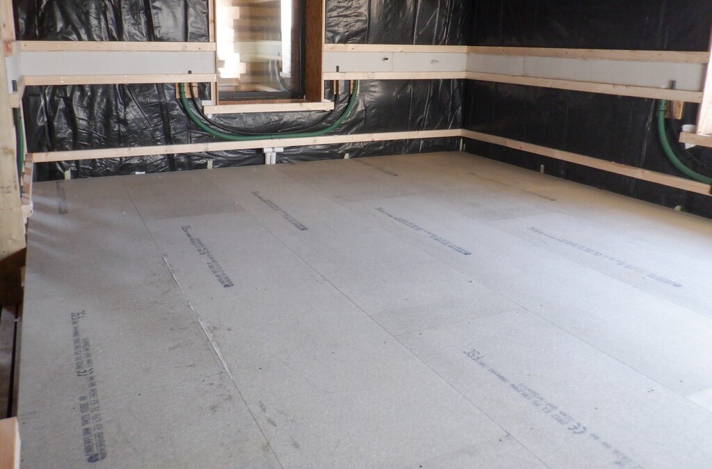
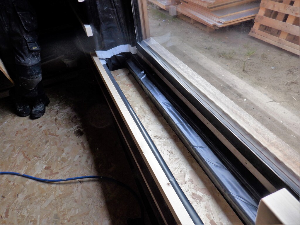
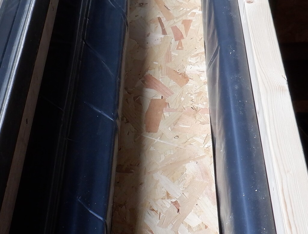
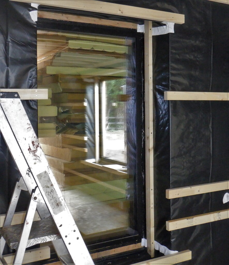
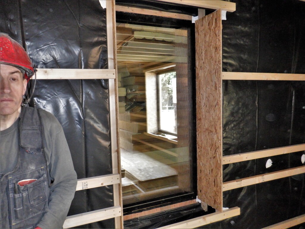
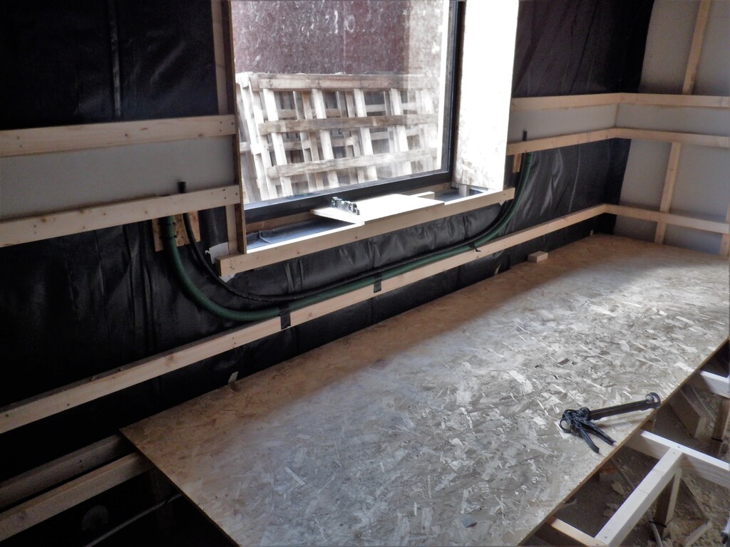
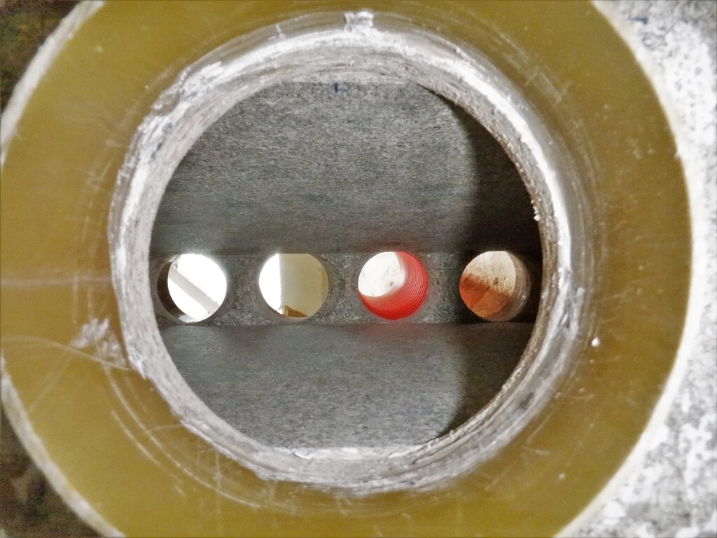
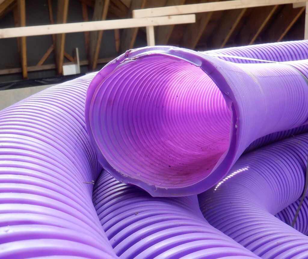
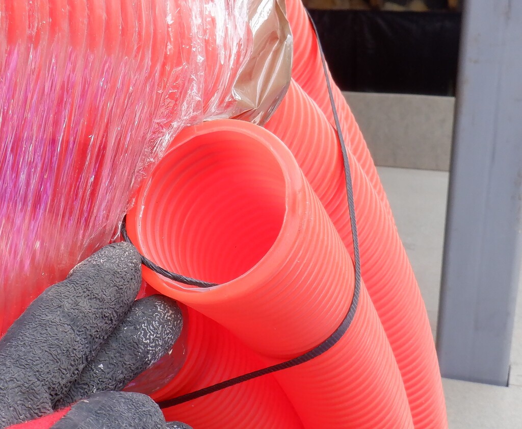
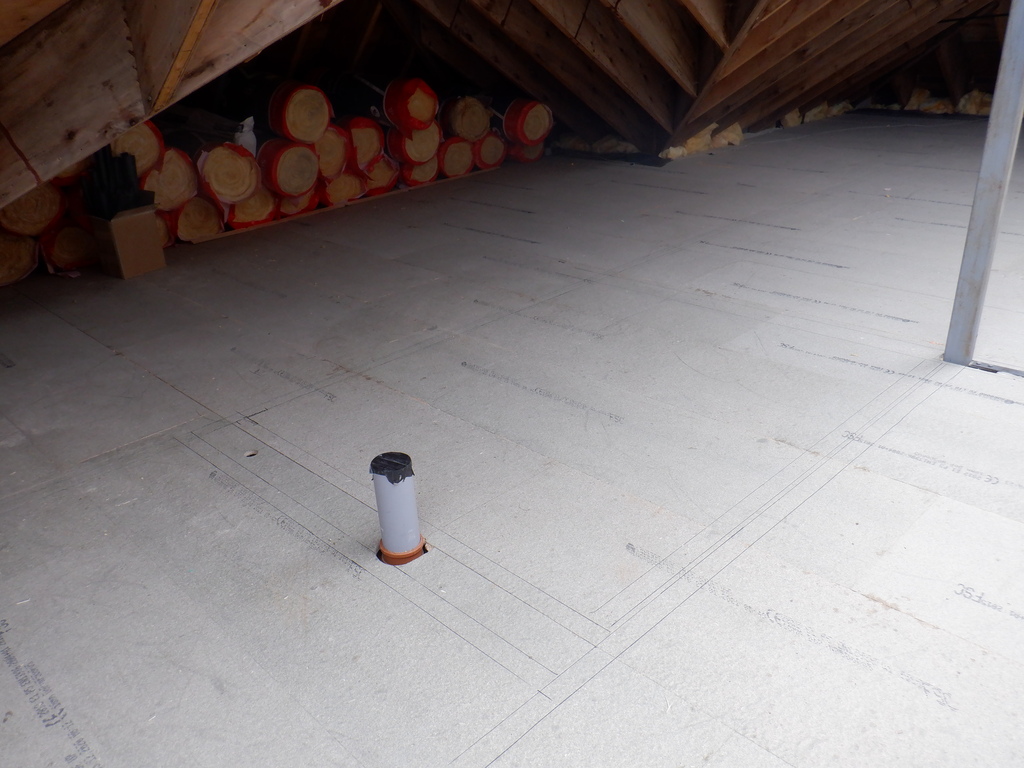
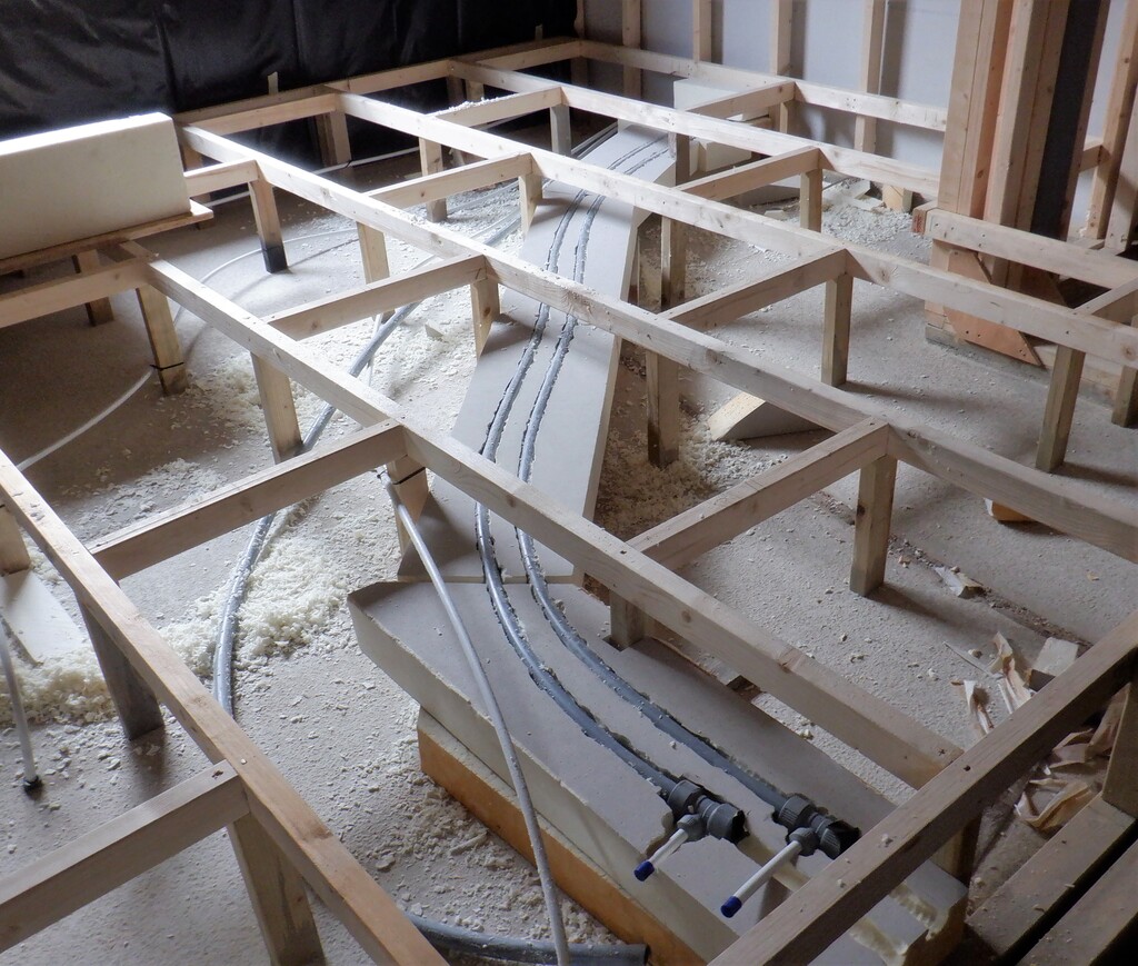
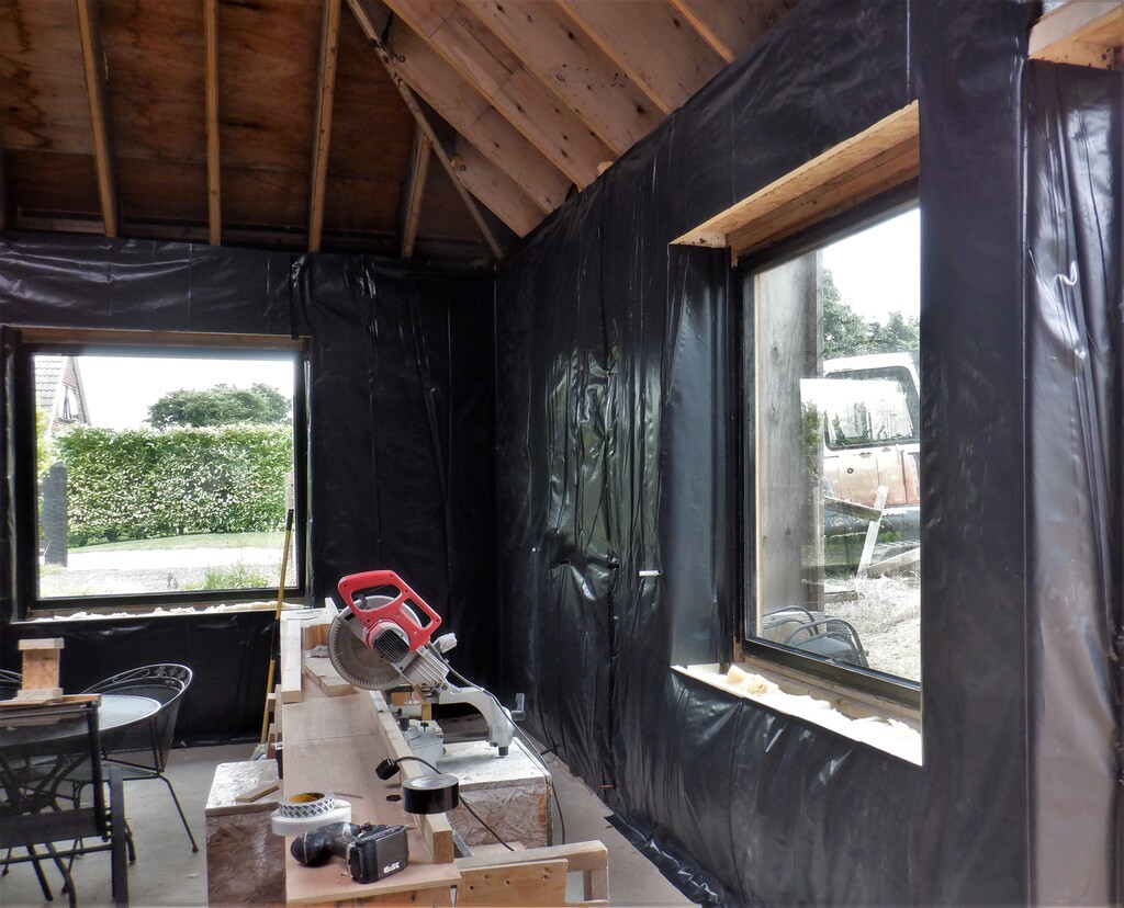
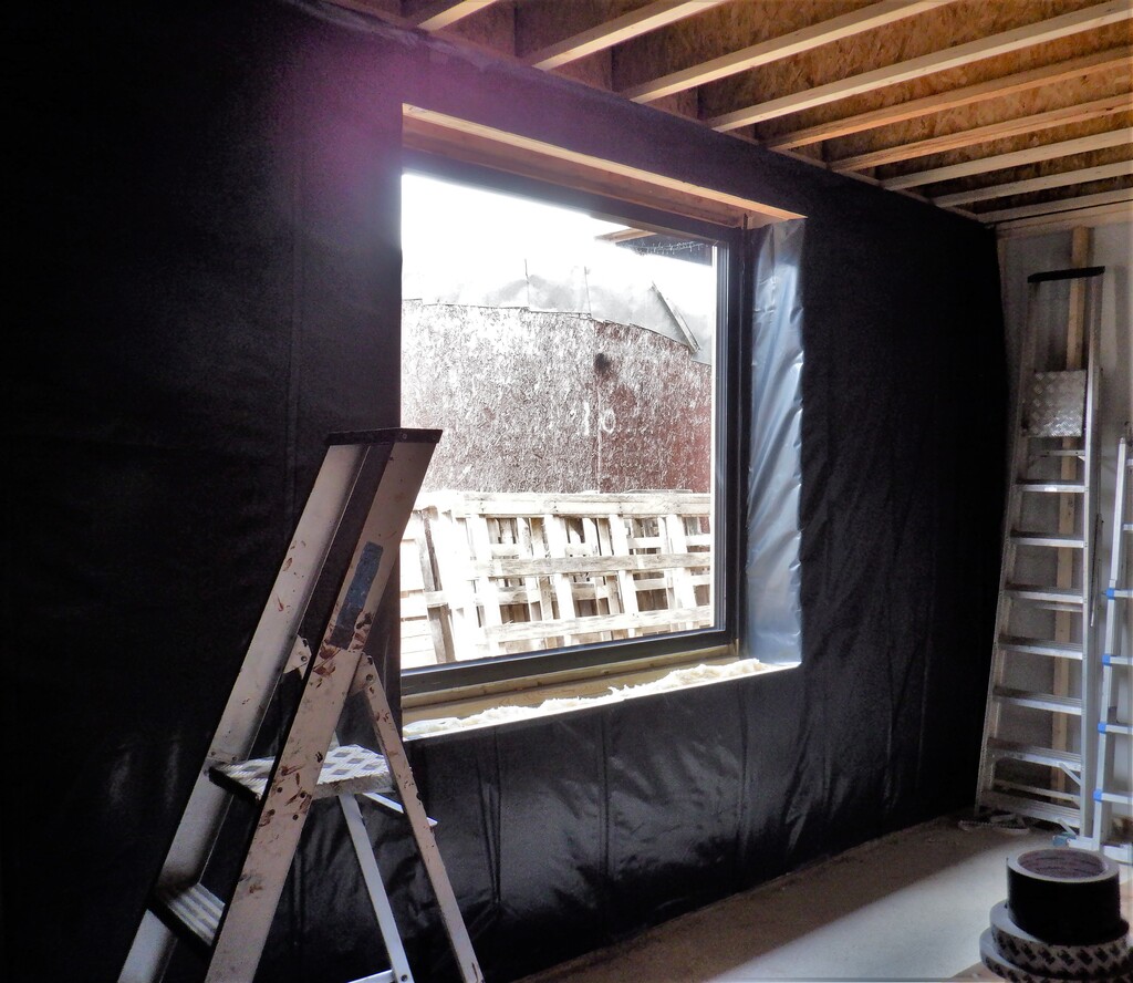
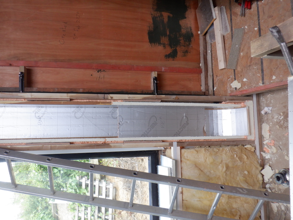
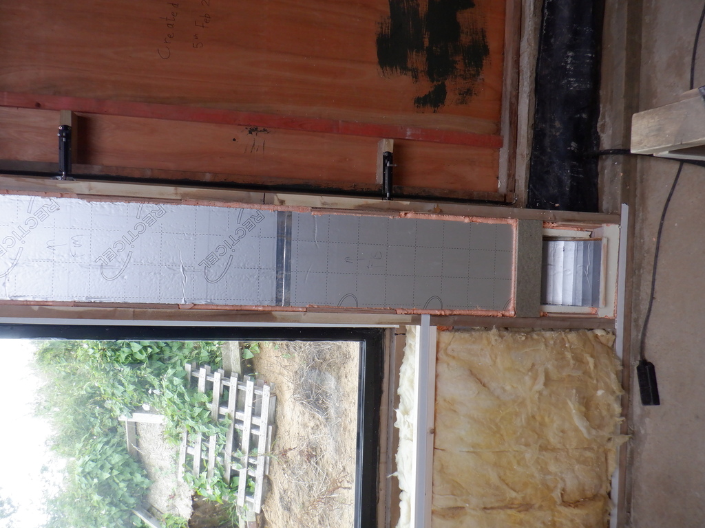
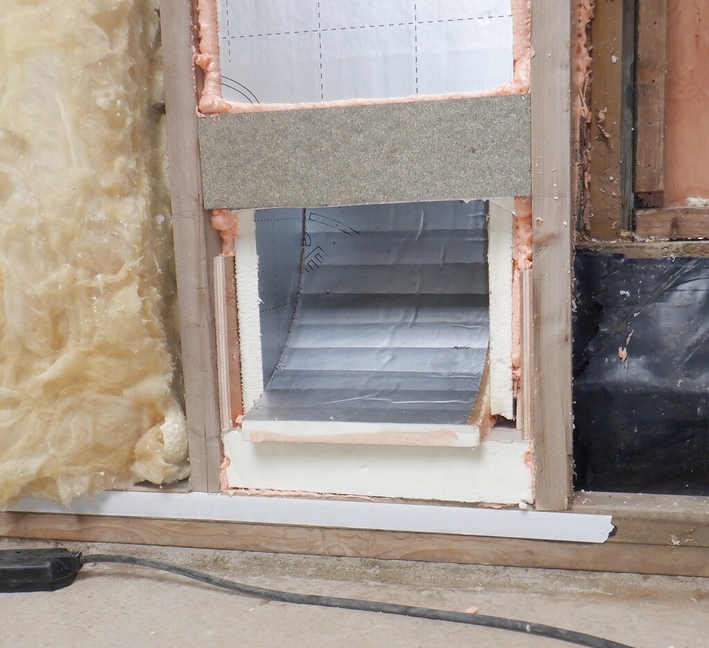
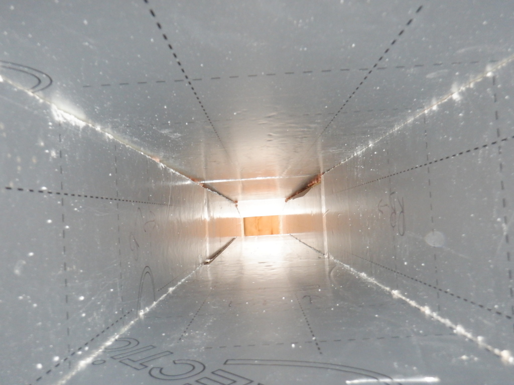
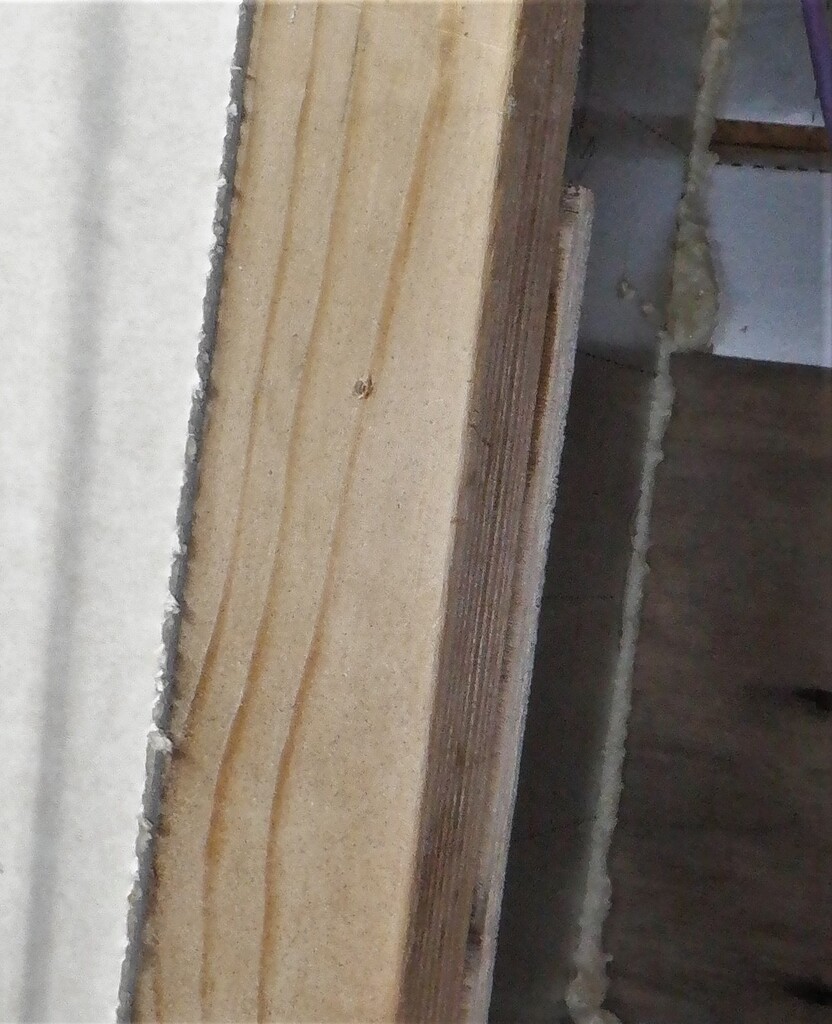
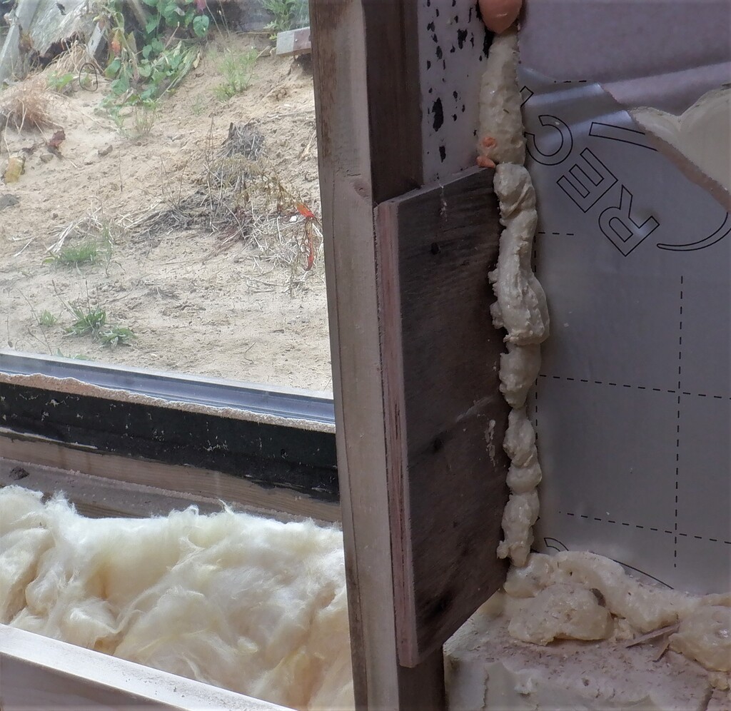
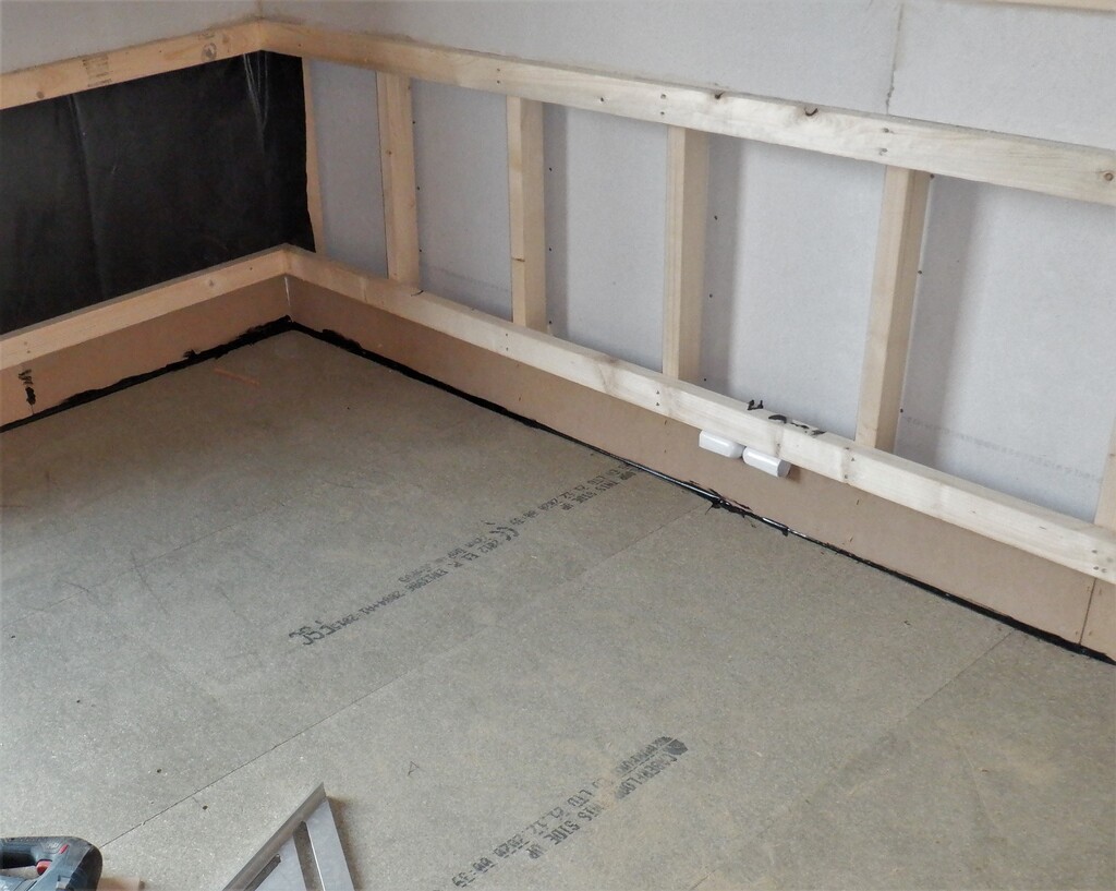
After having finished the floorboards for Bedroom 3, we can walk around much easier and inspect everything. We decided to swop out the cable conduits around the windows with our recently purchased rigid waste piping and also insert a another new piece of conduit, this time to provide access for power and signalling cables to the windows and their motorised blind mechanisms. We nearly forgot all about those!
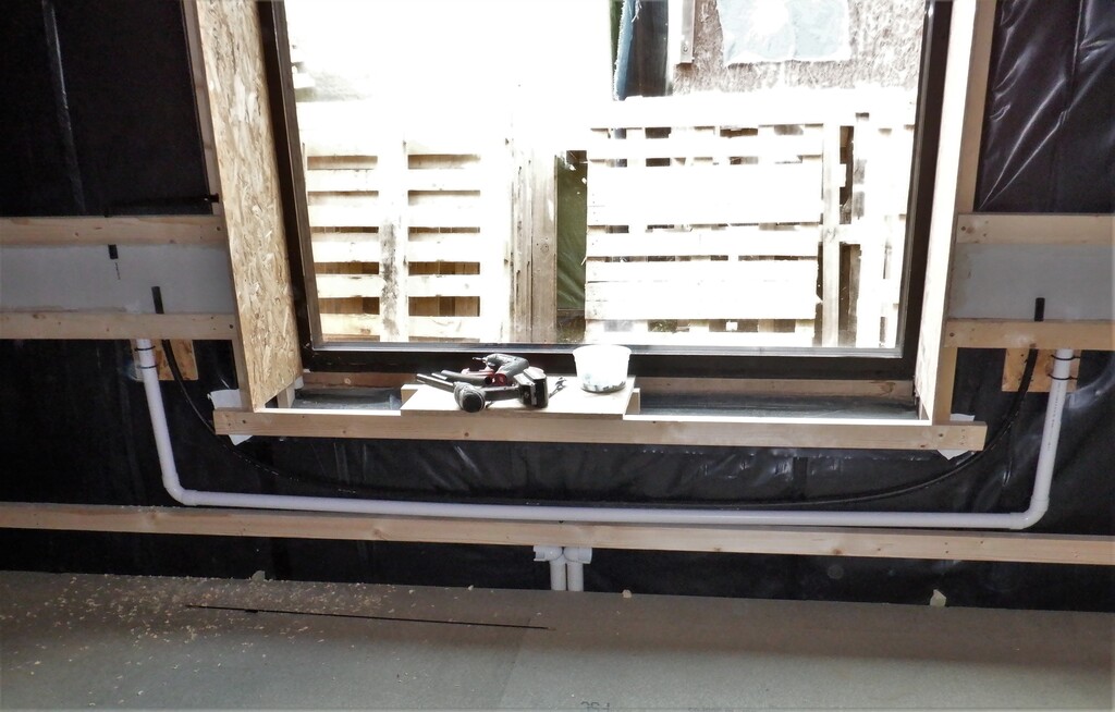
Replacement-window-bypass-conduit
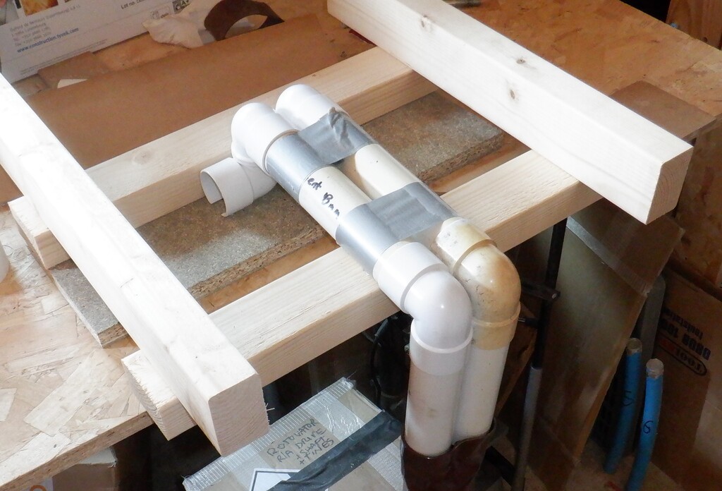
Window-control-conduits
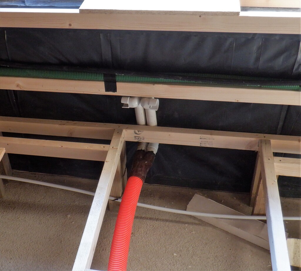
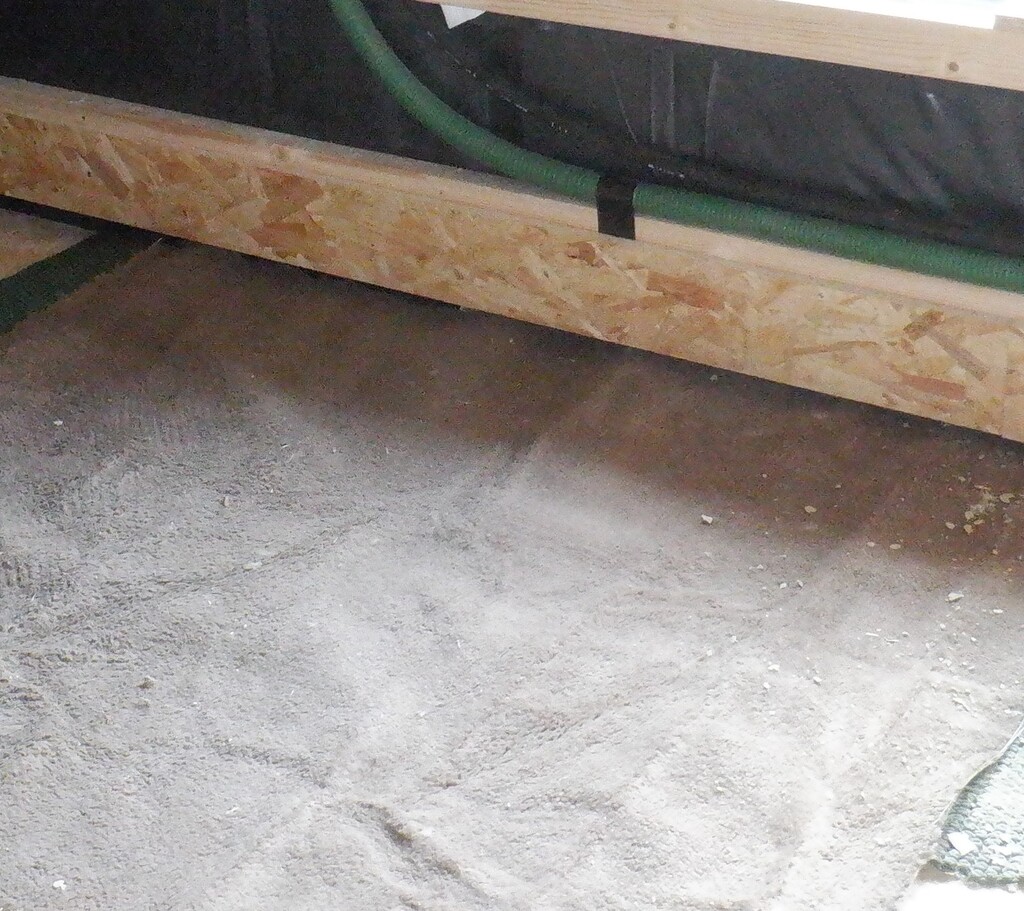
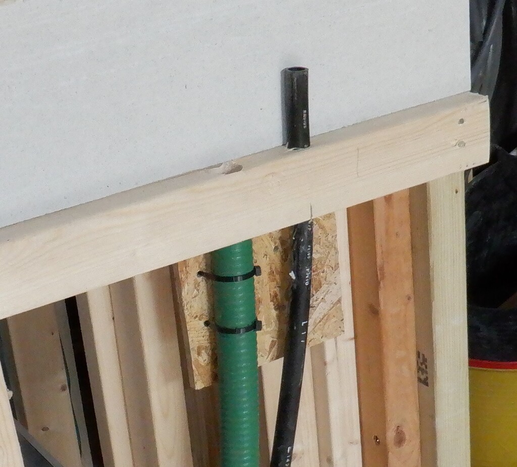
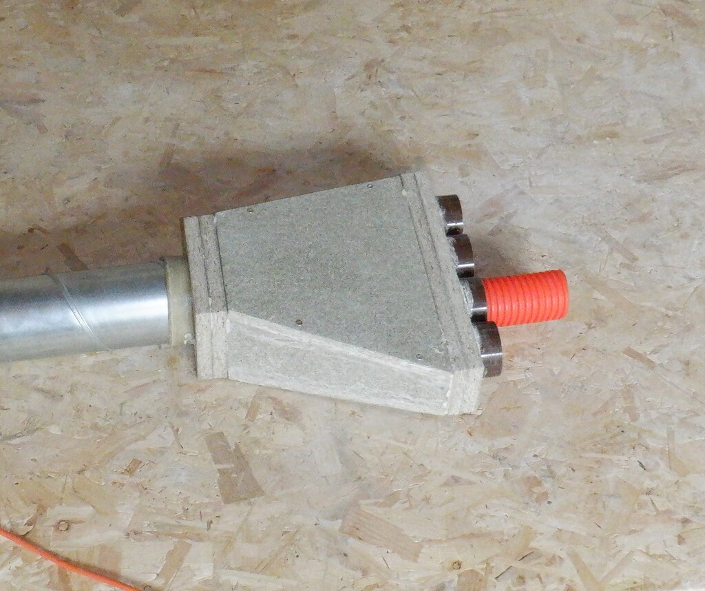
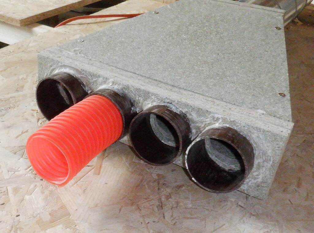
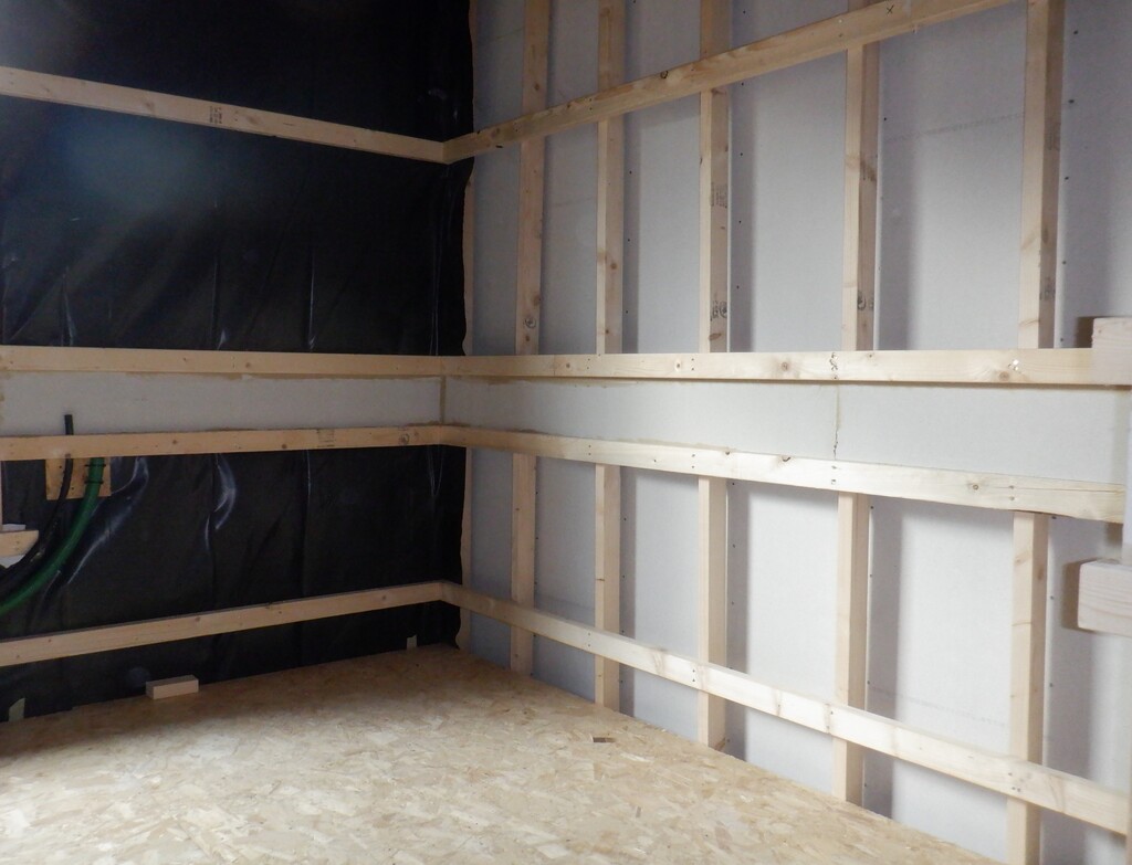
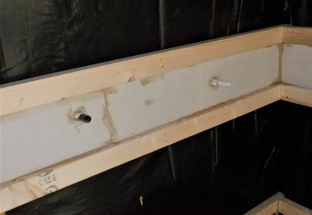
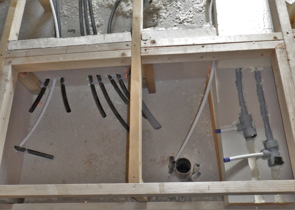
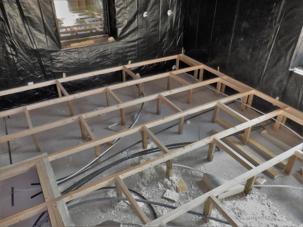
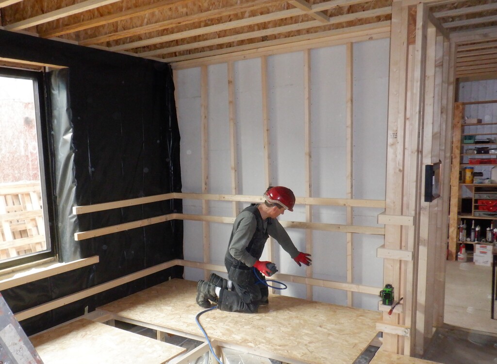
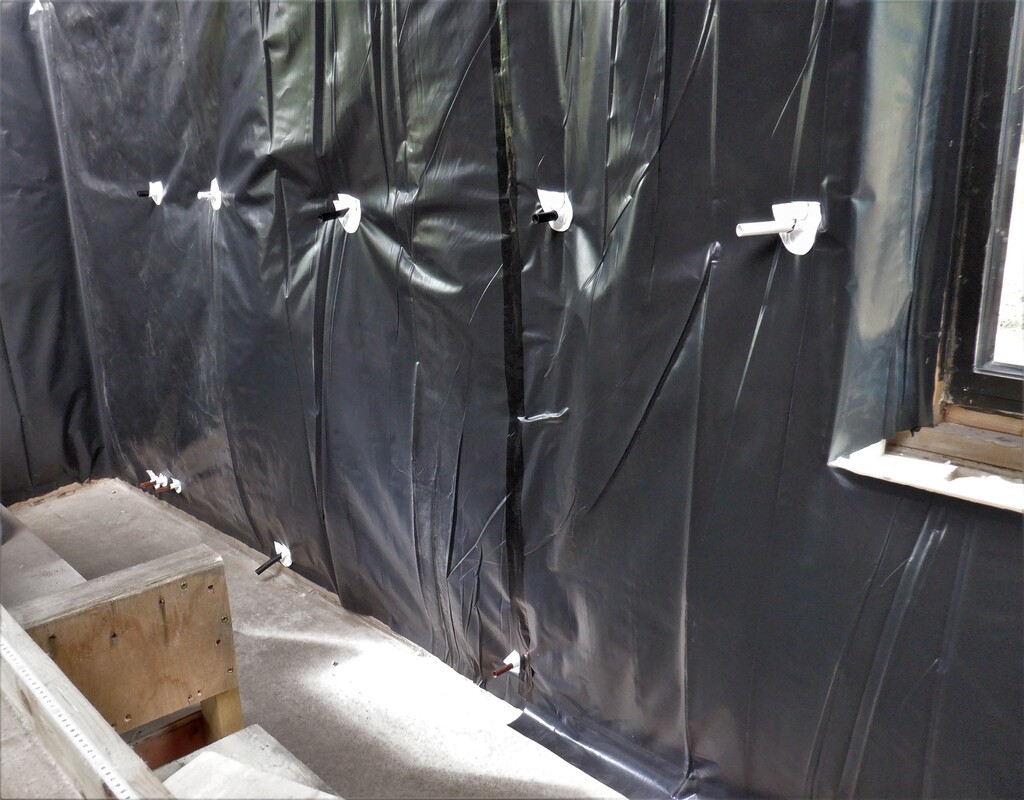
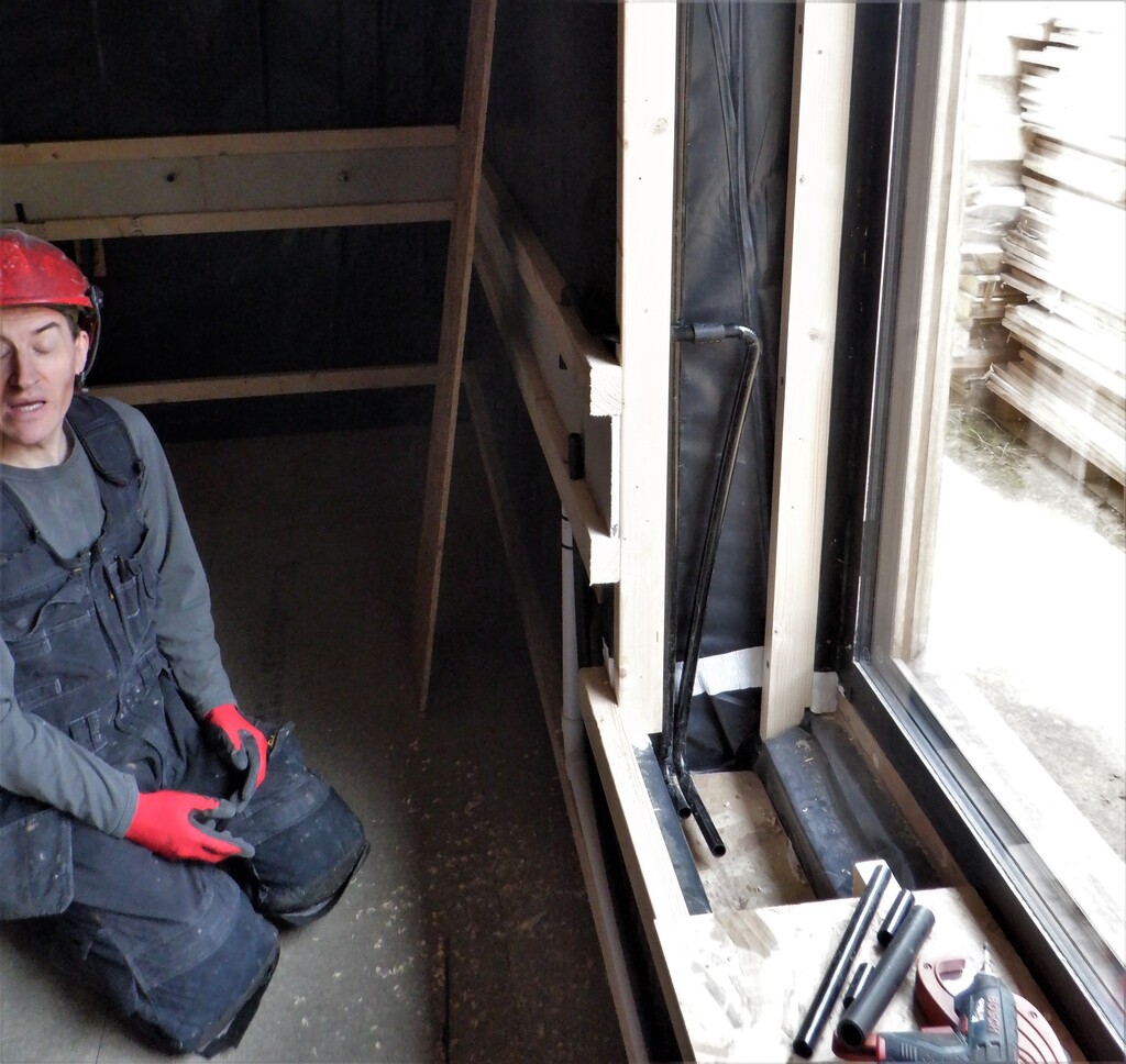
Another feature that we have been talking about is putting in a built-in hearing induction loop into and around the walls so we installed another length of conduit, running horizontally above the doors and windows using our stock of 20mm black polyethene pipes. We had to heat and bend much sharper corners because of the tight space requirement when traversing around the corner and having to keep inside the 38mm spacing limits. We made six of these tight bends and then used short 25mm diameter pipe to join them to the straight sections. The Loop started and finished at our Control Box which will house the induction loop amplifier. This is a very rare feature to have such a thing in a domestic situation, all built-in but having two people wearing hearing aids living here, we thought we had better provide the ability to install a loop later on.
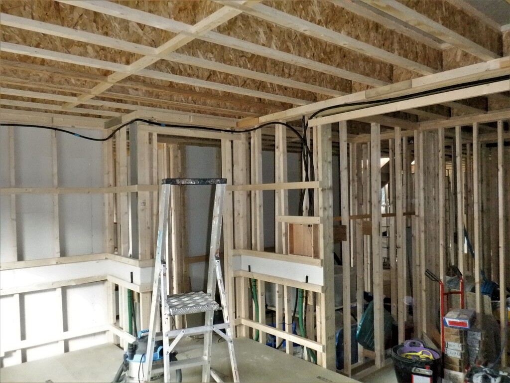
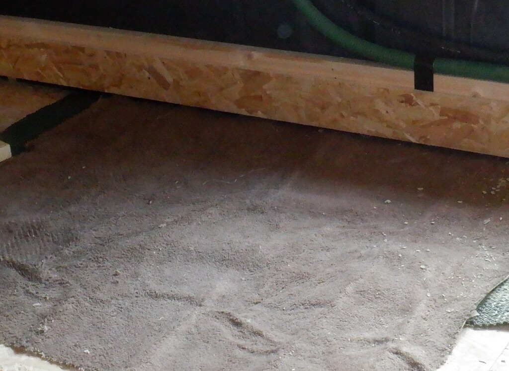
Conduit-for-hearing-loop-1
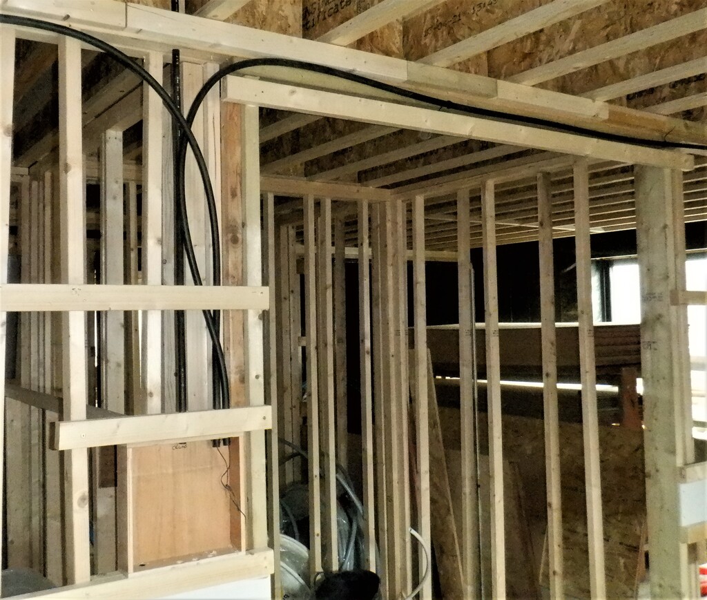
Conduit-for-hearing-loop-2
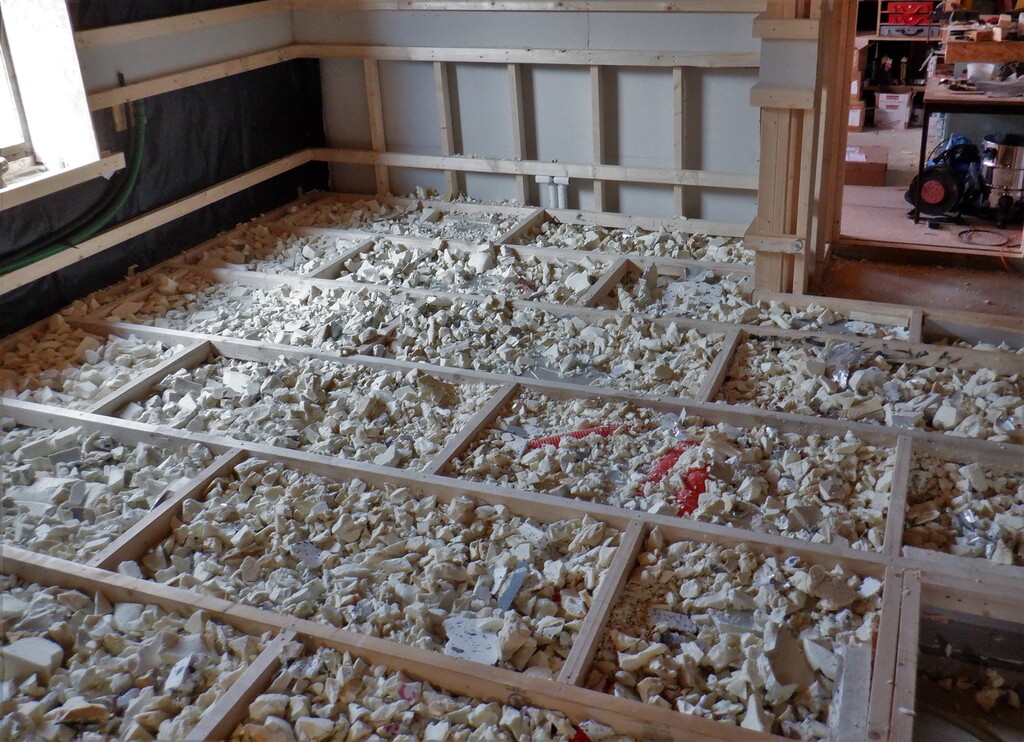
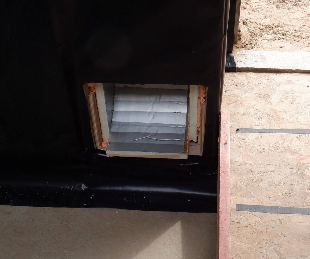
Then we used the left-over flexible 32mm conduits to put in the connection for our mass of low-voltage cables to start on each side of the entrance way.
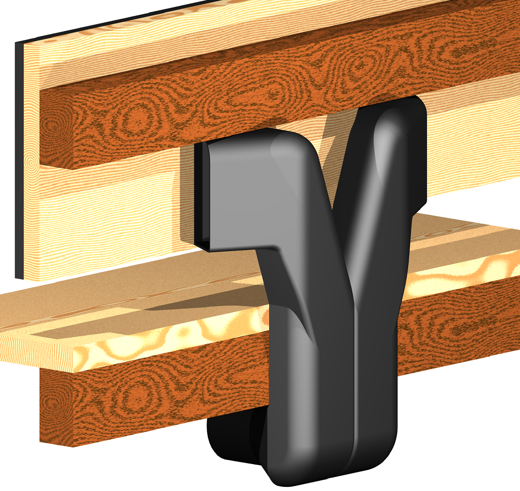
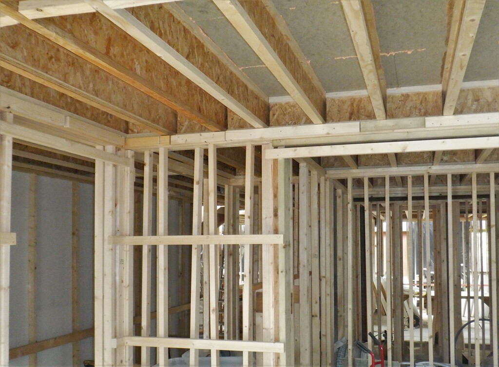
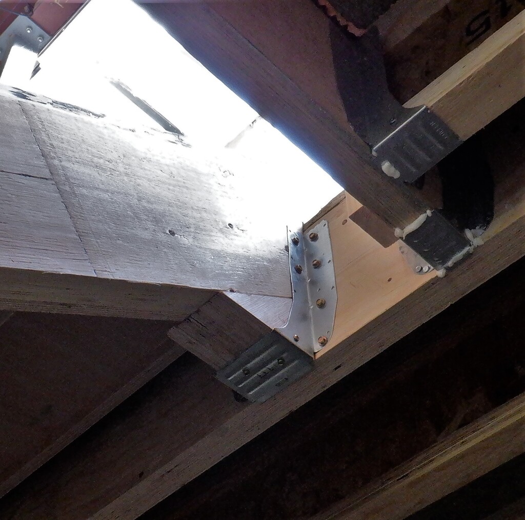
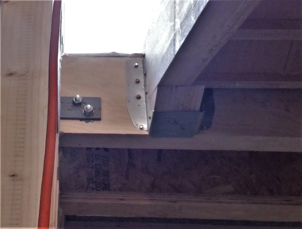
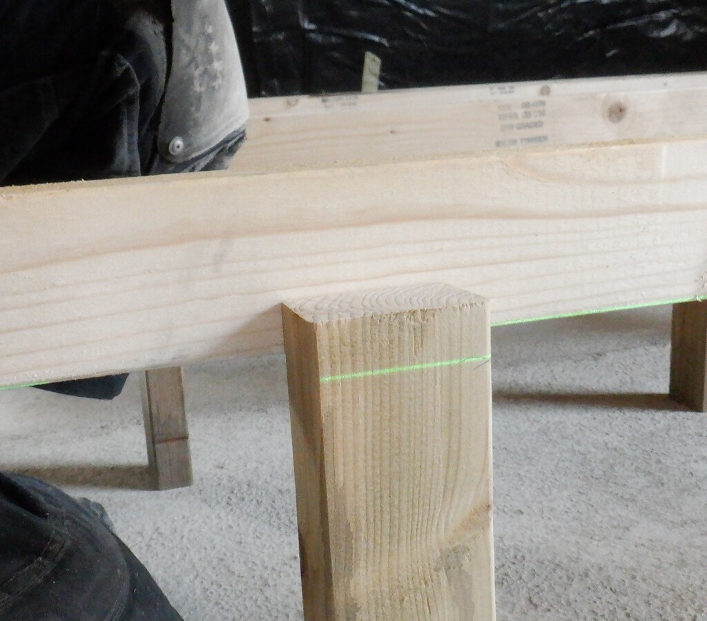
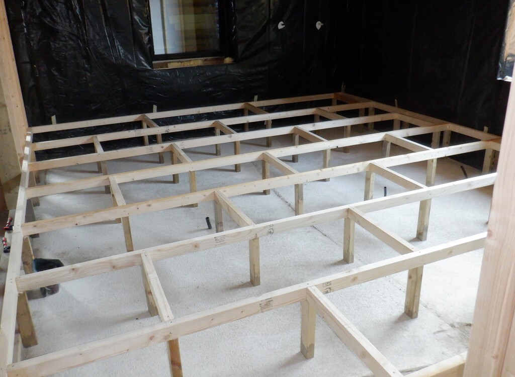
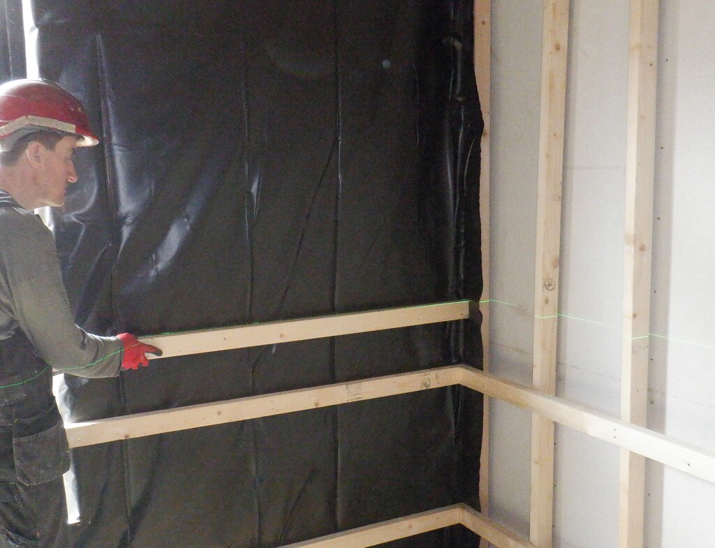
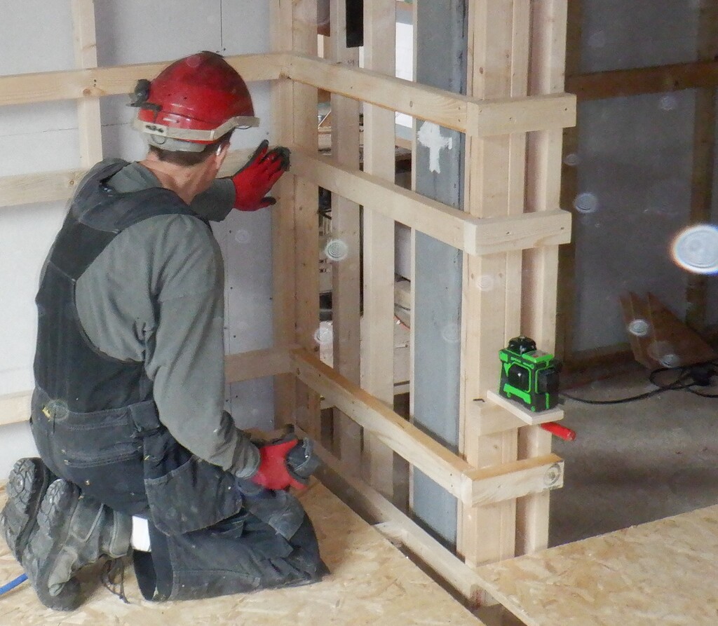
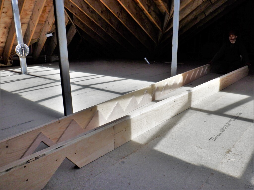
That concludes all the conduits for this room, we didn’t need to install a conduit for compressed air nor any other types like water or things like that. So we moved on to the next task of building the short stub wall and doorway to the en-suite. One of the first steps was to screw up a long piece of CLS 63mm timber at the 500mm height which matches the two windows in the room. We did this by using our green laser to ensure everything matched up. Then we measured to how far the toilet bowl would be sticking out from the wall and made sure that the door would be able to swing clear. It does mean that the doorway is slightly off centre but not by too much, some 410mm on the left side and 610mm on the opposite side. We used more of our “2by6” timber that we originally used to build the framework around the en-suite entrance, to make the stud wall and a flat top. We aligned the height of the little stud wall to the new horizontal rail we just put on so all three window like objects in the room all look very similar, with an oak sill on each one etc. We planed two pieces so it was nice and flat to go across the top of the stud walls and two vertical pieces underneath this flat top and goes all the way down to the footplates on the concrete. These were glued and anchored into place with lots of screws plus several battens too. The last piece of the 2by6 was to create the door sill sandwiched between the two stud walls, exactly 880mm wide which is our standard width for swinging type doors. We introduced a very slight slope to this door sill, dropping down by 5mm as one goes into the en-suite so that if there is a lot of water splashing about in the room, it is not prone to running out and into the bedroom.
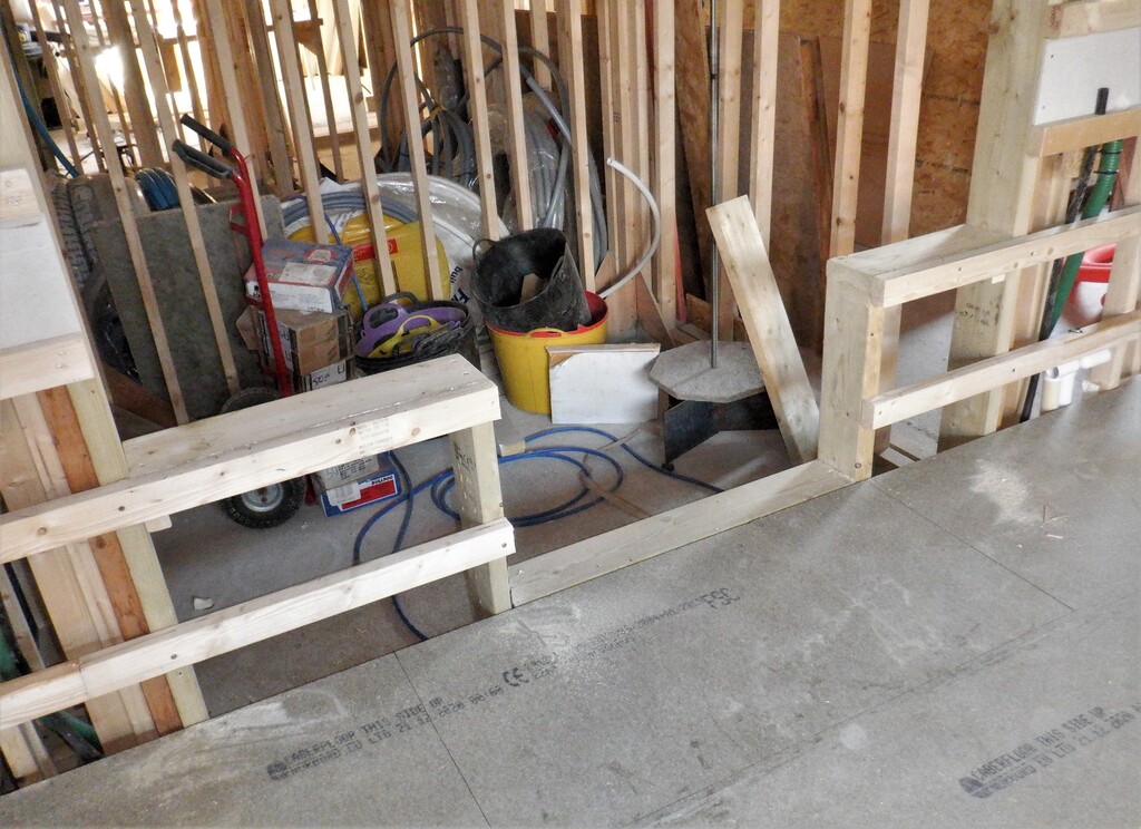
Ensuite-stubb-wall
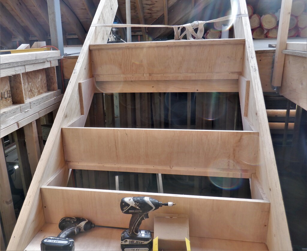
The next task is to slice up our heap of 8×4 MDF sheets into eight strips of 149mm wide per board, these strips go at the bottom of the walls to provide the back-panel to our air channel distribution system running around the bottom of the wall, completely all the way around the whole room. We went from post to post along the wall, stopping and starting on them to ensure that the ends didn’t flap in mid-air. We fired in staples on each post but also glued the top edge to the underside of the CLS horizontal rail so it kept the strips straight and sealed to stop air leaks. Talking about air leaks, the bottom edge was sealed using a black MS Polymer glue against the floorboards. Then we went around with a paint roller and painted the bottom section of the strip black to stop any chance of a gleam shining through when the room is finished and carpeted.
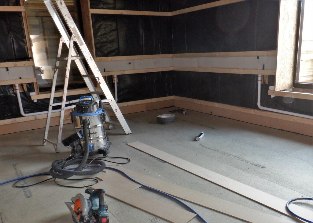
Air-channel-backing-board-1
Air-channel-backing-board-2
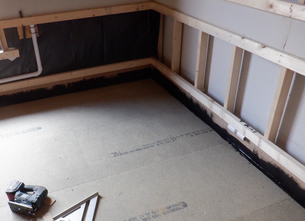
Painted-black
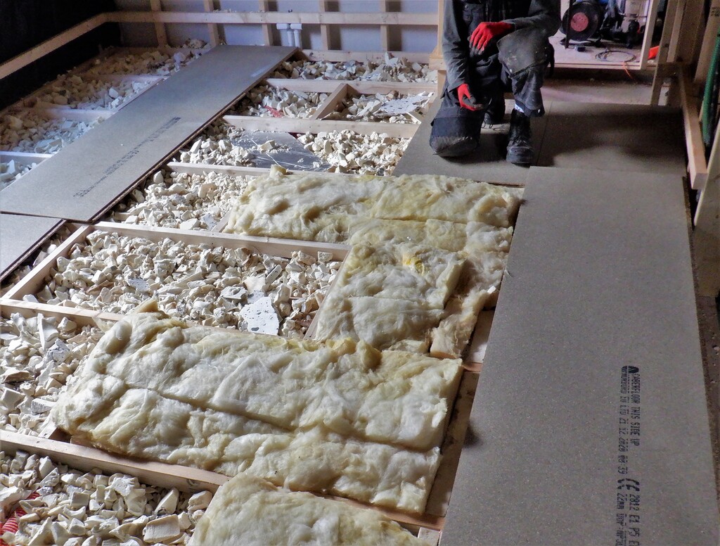
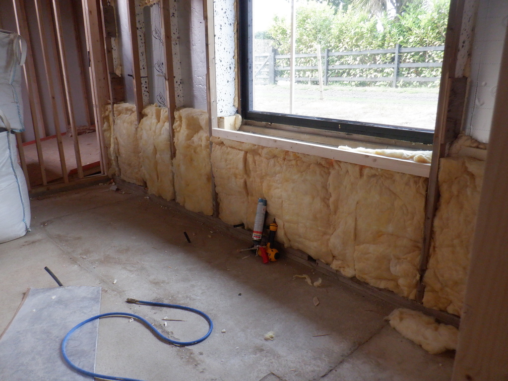
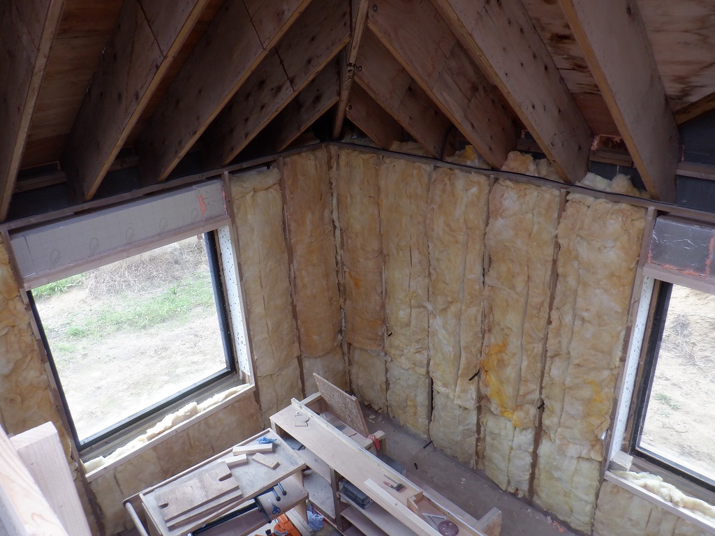
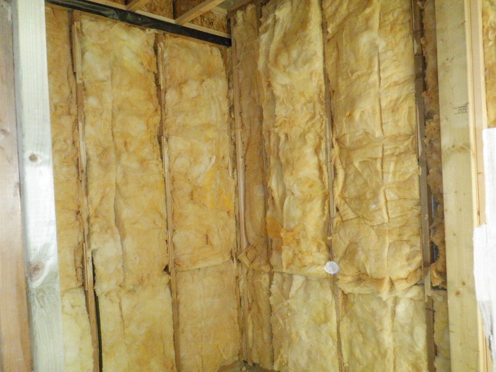
The next job was to put up the wall boards, the 18mm OSB sheets. Before we put them up we inserted the final layer of glasswool insulation between the horizontal rails, this is roughly fitted and is really just to provide impact sound dampening for the wall.
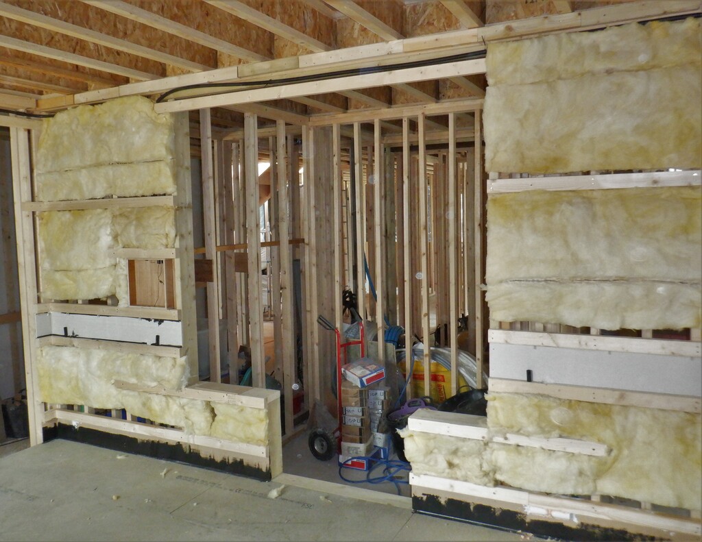
Final-layer-of-Insulation-1
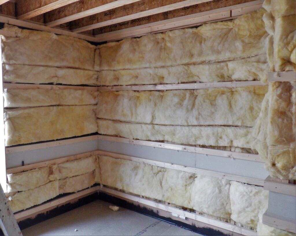
Final-layer-of-Insulation-2
Also, we went around measuring the height of the walls, from floorboard to ceiling joists and it came out to be 2415mm on average, fluctuating only a couple of millimetres. This height was designed so after the 15mm thick ceiling fermacell panels is installed, the room will have around 2400mm clear, about 7feet 10½ inches.
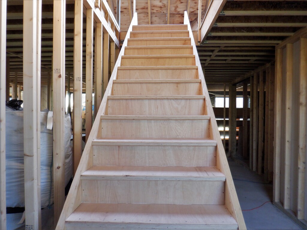
We then looked at the various methods of putting up these wall boards and we went for the more rewarding results by putting whole OSB sheets vertically from floor to ceiling in one go (instead of splitting it up into two halves, separated at the Utility Channel) and then cut out the Utility Channel afterwards and also deliberately overlapping the doors and windows so we can trim back the edges right back to the physical limits of these holes in the walls and get a much better finish. The next choice was how we would join the sequence of boards and part boards together along a wall section, we could either use a biscuit jointer or use a continuous tongue and groove method. We couldn’t decide so we went for the biscuit joining method first on the short wall that has the small window in it and proceeded to put in ten biscuits along the entire height with includes the extra ones around the bottom and top pieces that covers the window section. It was a bit fiddly in getting all the loose biscuits in and then slicing the two boards together but it was workable. The big problem we had was with the glue as it was taking us a good 15 to 20 minutes to get all the pieces ready, with their joints and biscuits and we were using the PU spray gun glue foam because it was a very handy tool to just spray the glue into place, but these spray expanding foam don’t have a long “open” working time before skinning over, even this especially designed foam to work more like a glue still has a short time before it skins over and cures. We did manage it by doing it in stages and we got the first wall up and screwed in place. That is another thing, we decided to use screws instead of nails, just like the floorboards because we wanted to know that the boards were being tightly pulled back onto the support horizontal rails and squeezeing on to the glue.
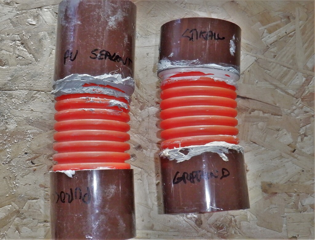
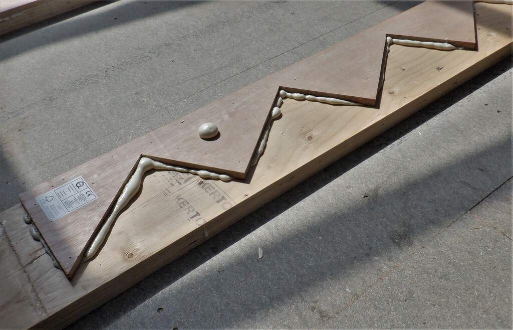
We needed a glue which stayed usable for longer and after much discussion over different glues, and doing several tests (we put out three blobs of each glue, and then waited 5minutes, 10minutes and 20minutes to see if and when they skinned over and whether the joint was affected by screwing in small pieces of MDF material), we concluded that the solvent-free construction glue was suitable because it is both cheaper and less messy than the other choice of the PU construction type which worked the best (and the third glue, the Skixall performed the worse because it started to skin over by the 20 minute point but still did a good strong joint).
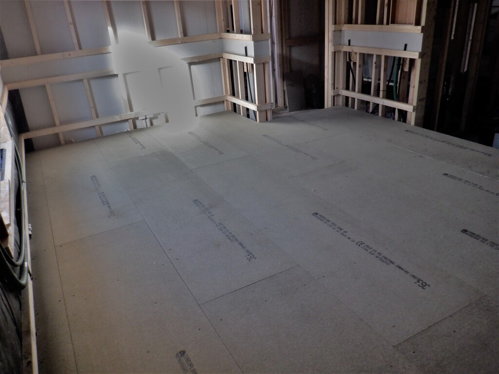
Before we resumed putting up more wall boards, we felt that we should make sure that we could cut out the Utility Channel so we got our track saw out, drilled a series of mounting screw holes and then using our green laser line generator, mapped out on the finish wall the 800mm and 900mm levels, drawing two lines. We also decided that there will be a 38mm uncut area at each end of the channel so that the covers didn’t have to go right into corners or right up to the edge of a window or doorway. We then proceeded to mount up the track guides onto the wall and sliced two horizontal cuts into the OSB board, then finishing off the cuts using our wiggle saw. After tidying up the cut edges with sand paper, we now have our first Utility Channel ready for use, for our sockets and speakers and whatever else we may want in a room.
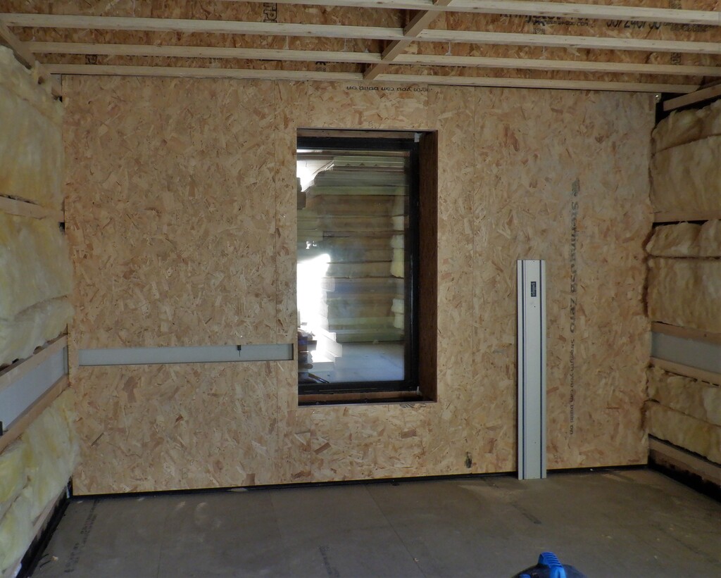
First-walls-OSB-installed
Another little job we did was to make a magnetic clamping system for our green laser line generator because it would be much easier if we could put up a vertical metal ruler with pre-determined positions of various elements we have in a room and be able to move the laser up and down easily without having to use a clunky screw clamp. So we put on a long metal band on a piece of wood and glued in two strong magnets into the laser’s little shelf. We did have to add a coat of a rubber like spray on paint to increase the friction between the metal and magnet as it had a tendency to slide down under the force of gravity!
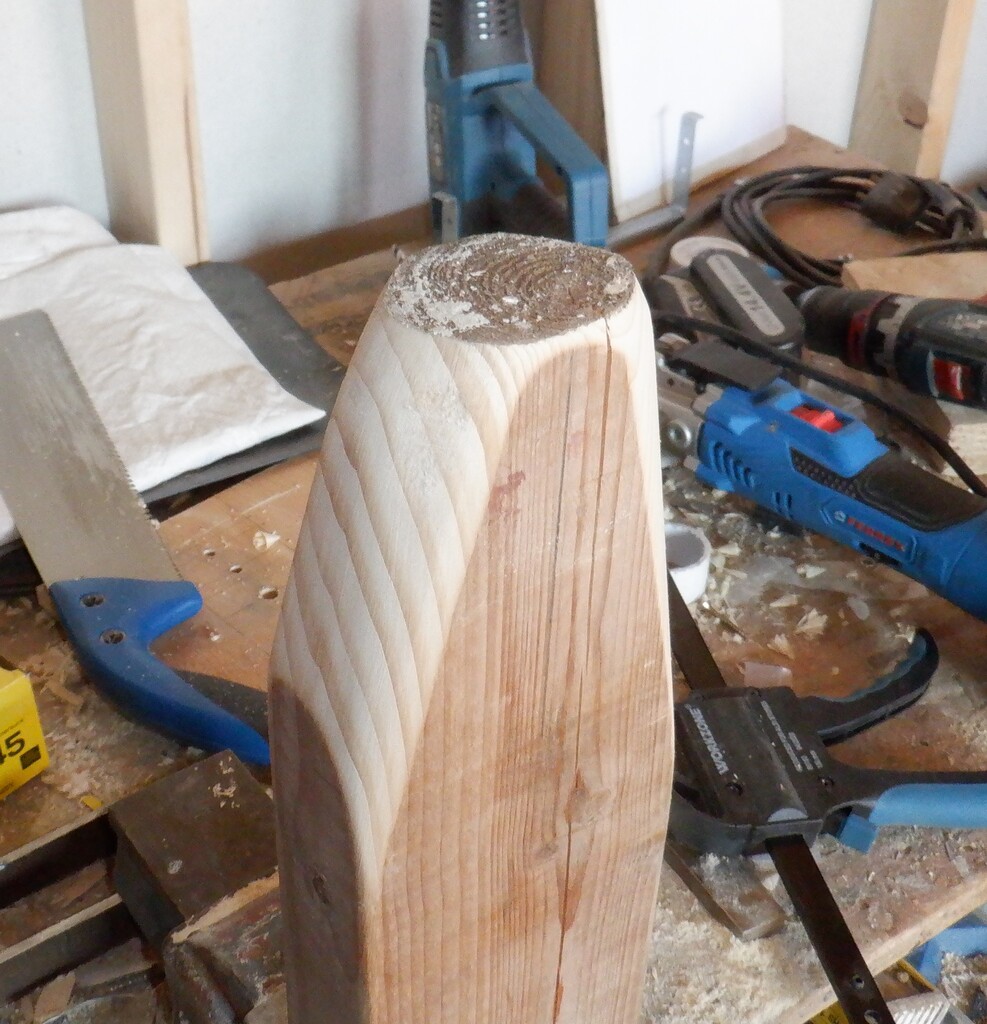
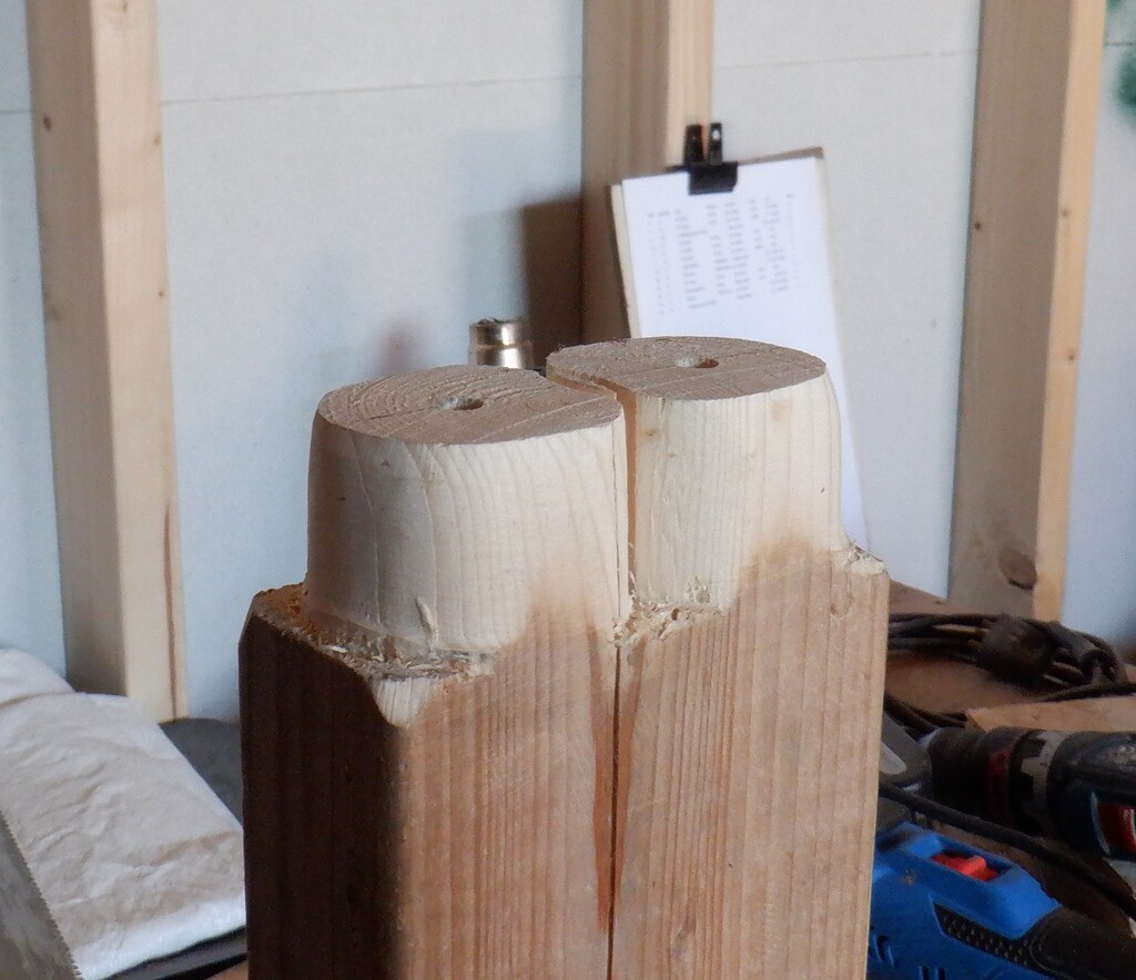
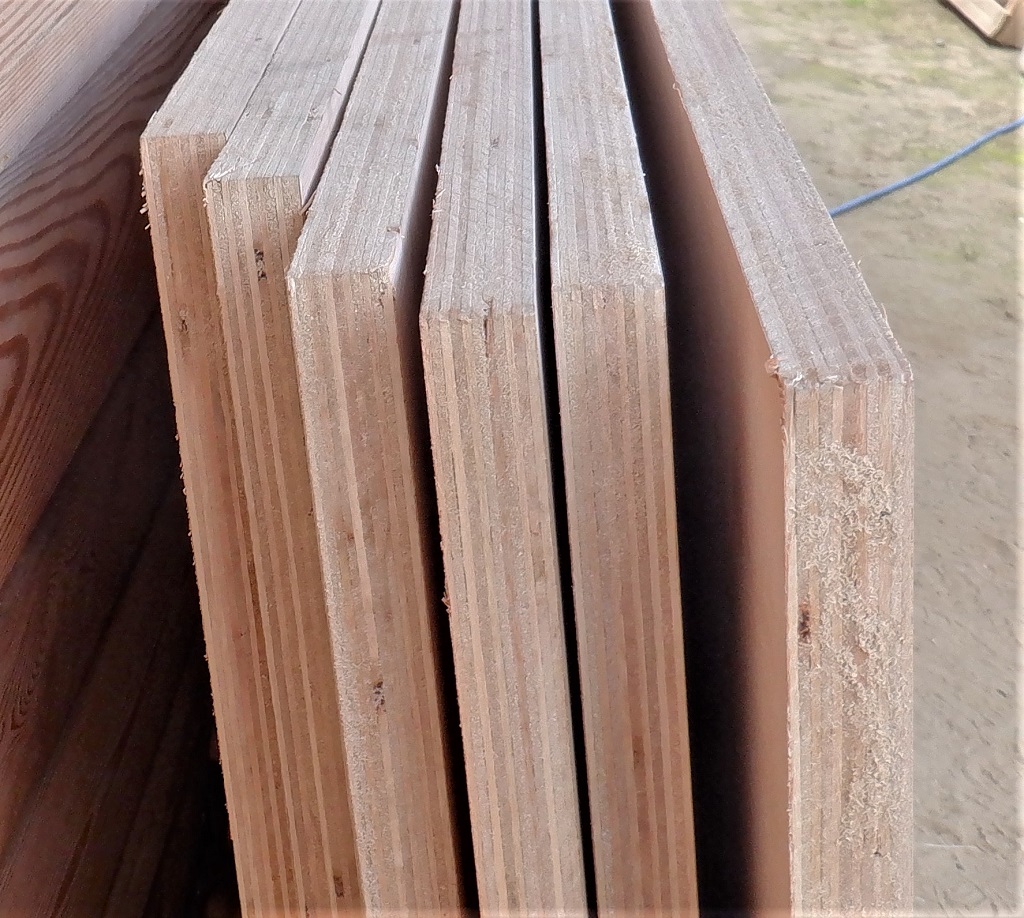
Finally, for our next section of wall, along the “H” wall with the large window in it, we decided to try out the tongue and groove method of joining the boards together and see how well (or not) it performed. We got our two router machines out and set up the two cutters, one to make a groove 13mm deep and the second one to cut a tongue 12mm long. These are parallel straight 90degree tongues so it may give us some fitting issues when we get to try it out next week. The machines are now setup and the test pieces look good and form flat and smooth joints so it is promising.
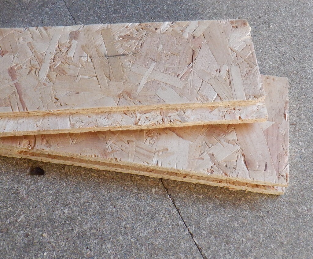
Tongue-Grooving-edge-of-OSB-1
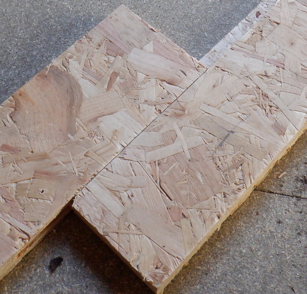
Tongue-Grooving-edge-of-OSB-2
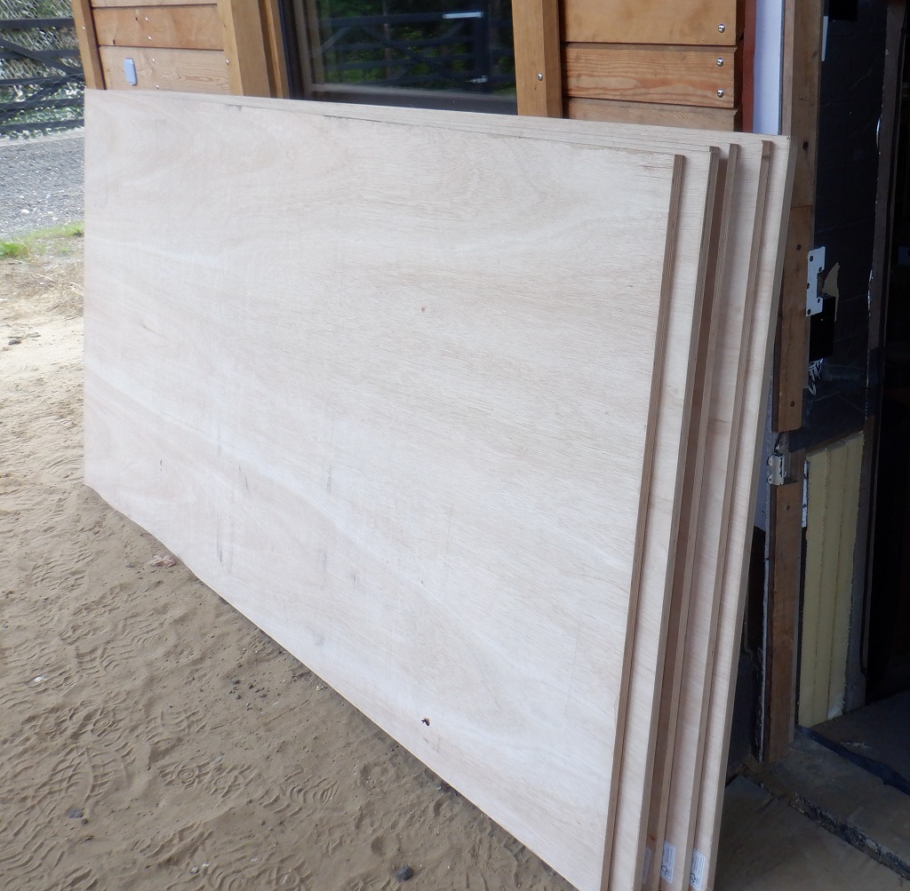
The last thing we did was to bring in a dozen more sheets of our 18mm OSB boards from our storage piles outside under canvas, we will need at least eight more boards to finish off Bedroom 3.
Oh yes, we moved some of our LED flood lamps from upstairs and mounted them into the back bedroom where we have all the sheet materials and several lamps in the room we are doing because the place is getting darker with the rooms being built and blocking off light in all directions!
Next week, among entertaining family members, we will continue putting up wall boards and even maybe a layer of the fermacell (plasterboard like material) on too and get to see an almost completed room, apart from the ceiling and the doors for the en-suites etc.