This week, we completed the task of inserting at least one layer of PU foam board up into the rafters that we can reach from the First Floor .. the other half of the building, along the back doing sections M, L, K, J and I.
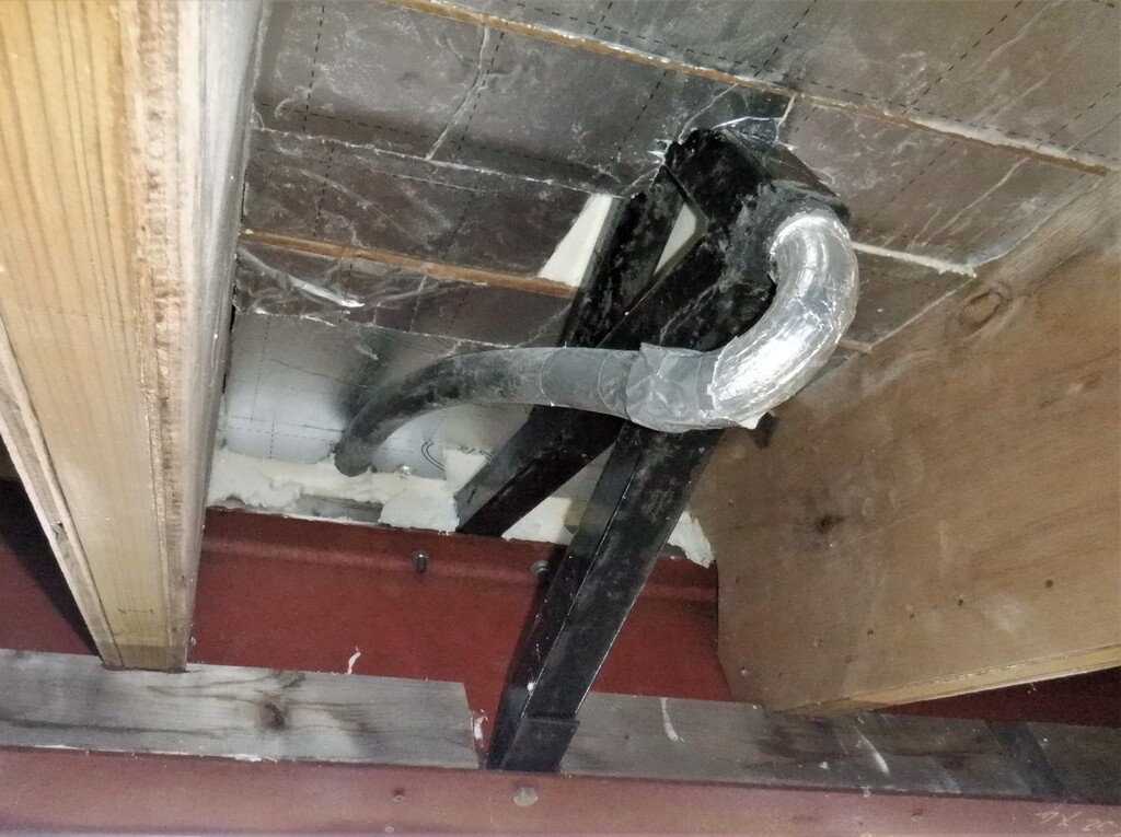
The task we thought we ought to do next is to make a couple of unusual air duct channels, to take the hot air out of the Skylight. We used the rafter space itself to encapsulate the air duct tubing so it is hidden and does not intrude into our living space. We had one down near the Great Room and the second location is right down at the other end of the Skylight where it squeezes through a narrow opening just before the hip section of the glass.
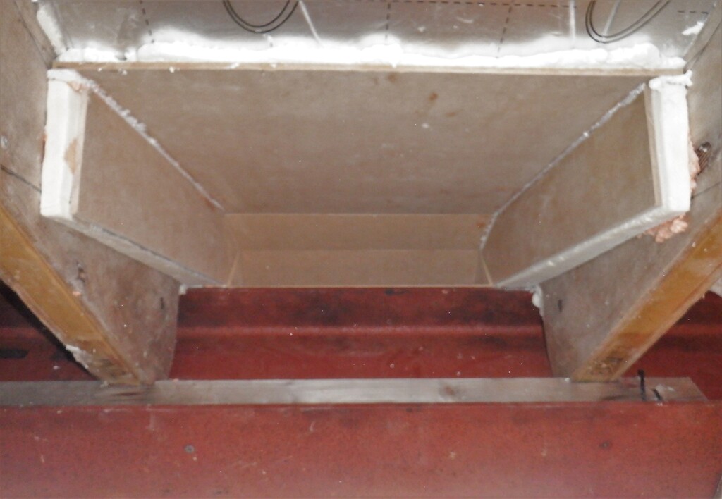
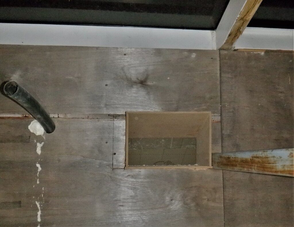
We had to cut our way through the kerb and all its layers of material, removing everything down to the steel RSJ surface, making a rectangular shape hole but with a tapering top surface to guide the air downwards.
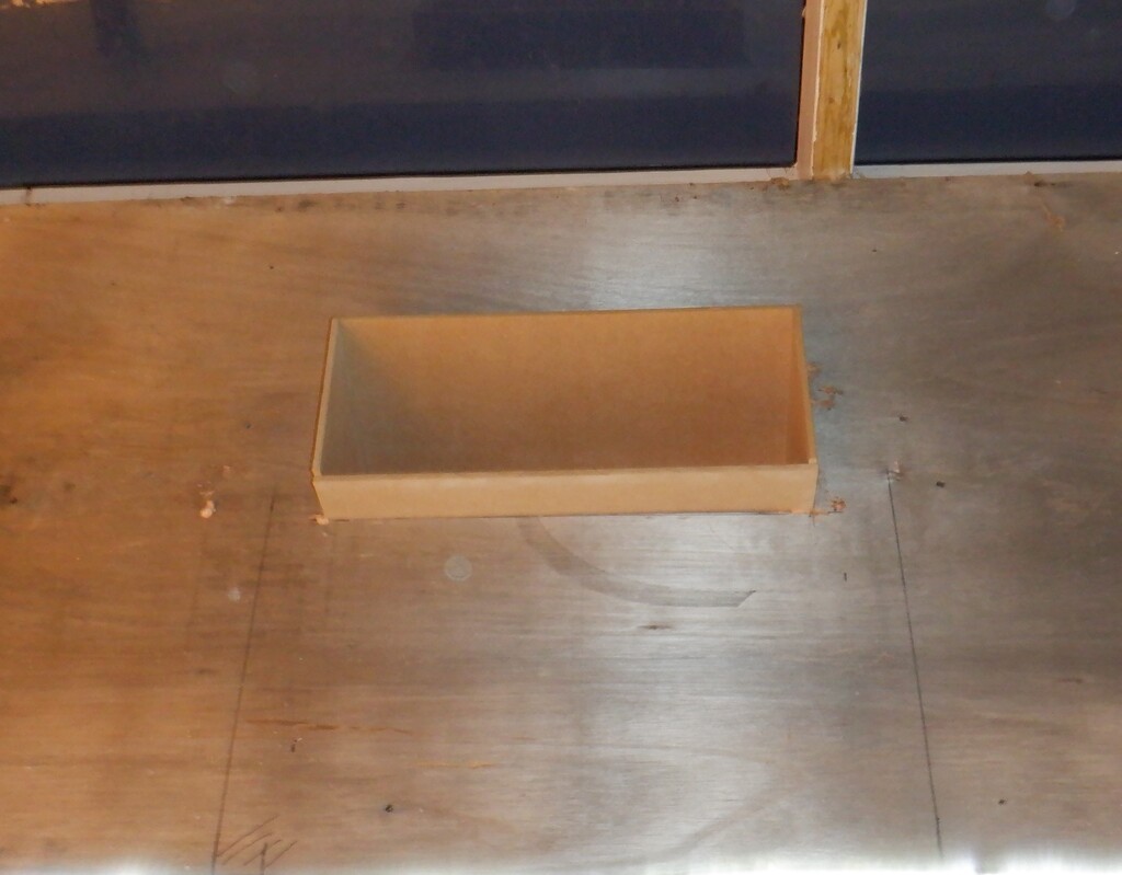
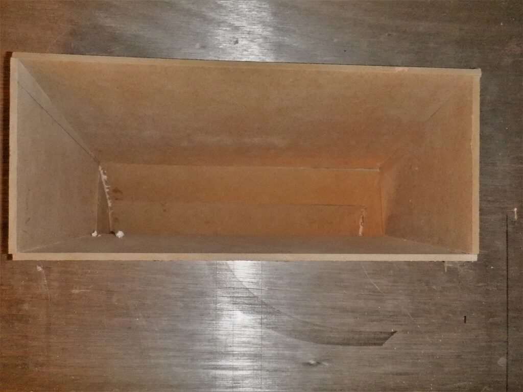
We used 6mm MDF sheet material to create the liner for the chute, to go over the steel RSJ beams and bend downwards to the bottom of the rafters, where the air is then transported down using more smooth insulation boards and this travels down before sweeping sideways to join into the main air duct that will be built to run around the whole house.
These MDF pieces were all glued in using our glue grade expanding PU spray foam, putting in lots of clamps to hold them in place while the glue sets.
Skylight-duct-M-1
Skylight-duct-M-2
Skylight-duct-M-3
The size of the first chute near the Great Room is approximately 500mm wide by 100mm high, with a slight squeezing as it travels over the RSJ but having a 50,000 square millimetres capacity is about half the total capacity of our main air ducting that the fan is designed to work with. It is that size because the skylight and the Great Room will be collecting a great deal of sunshine energy during those sunny days and we need to make sure we have the capacity to remove this hot air easily without struggling. It is so much cheaper to design in a high capacity air ventilation system in the first place, combined with our super-insulated roof and walls, would mean that we don’t need to burn large amount of electricity to run refrigerated air conditioning units to cool the house down. Invest the money in the insulation at the beginning, a fixed cost and avoid the running costs later on especially if the world is facing large temperature rises.
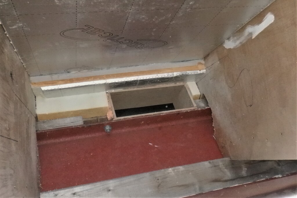
Anyway, we did the second chute as well, with a similar design using MDF pieces but only 300mm wide by 100mm high, before spreading out to the full width of the rafter like before. We also put up more layers of foam boards up and down the rafters themselves.
Skylight-Duct-I-1
Skylight-Duct-I-2
Another job we did was to drilled a conduit hole through the kerb at our ‘chimney’, to allow a 40mm conduit to connect to the bottom of the metal arm and vertical pole. The vertical pole has a 40mm conduit going up the inside and poking out the top, ready for the electrical connections to all the devices that will be mounted into and on the chimney when that is built later on.
Chimney-conduit-passing-through-kerb
That is about it for this week, we will finish off those two special ducts, plus one more that is needed for the upstairs toilet and shower room, which also has to come over the steel RSJ but we only need a simple 100mm round hole to let the flexible air ducting through. The other job to finish off is dealing with the last huge pile of PU foam boards which we will slice up and insert in places up in the roof rafters, just to get rid of them.