We started another job recently, this time to design and create our Vanity Unit for our Cloakroom. We wanted a simple design, in a natural darker colour, to match the décor and not to be too big, or too small, but just right! We always liked the design of the basin bowl to be “cut” into the vanity work surface itself so that everything is flush and smoothly flowing from one surface into another.
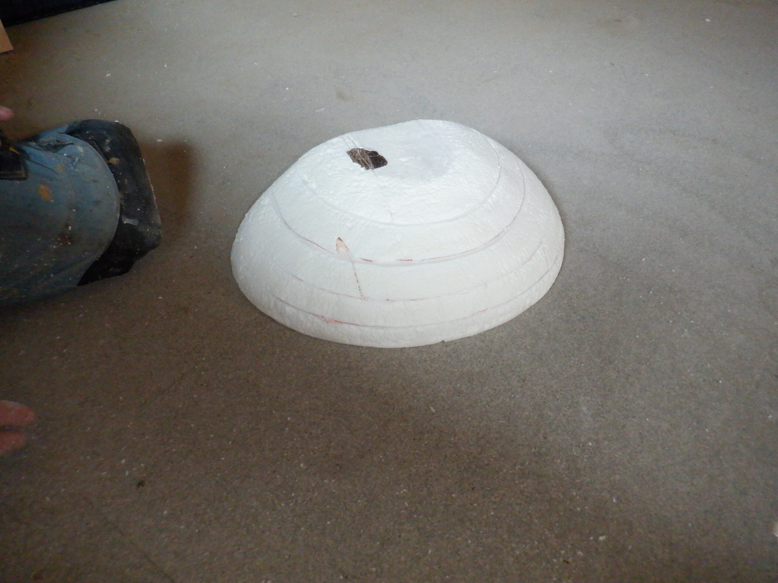
So, the first job is to design and make a mould for the bowl itself. We glued together five layers of 25mm thick insulation boards, the largest one measuring 270mm wide by 450mm wide, shaped like a letter D. Then, the next layers were consecutively shrinking smaller around the curvy parts, but aligned up on the flat edge. It is now looking like a domed shaped pyramid, with the steps to get to the next level. We then, used a surfform shaper to remove the excess material from these steps, to smooth out the whole thing into a gentle curving bowl.

Starting the bowl blank
We then scraped around the flat back edge, to give it a pleasing softness to the two outside wings and scraped all over the bowl to improve the shape.
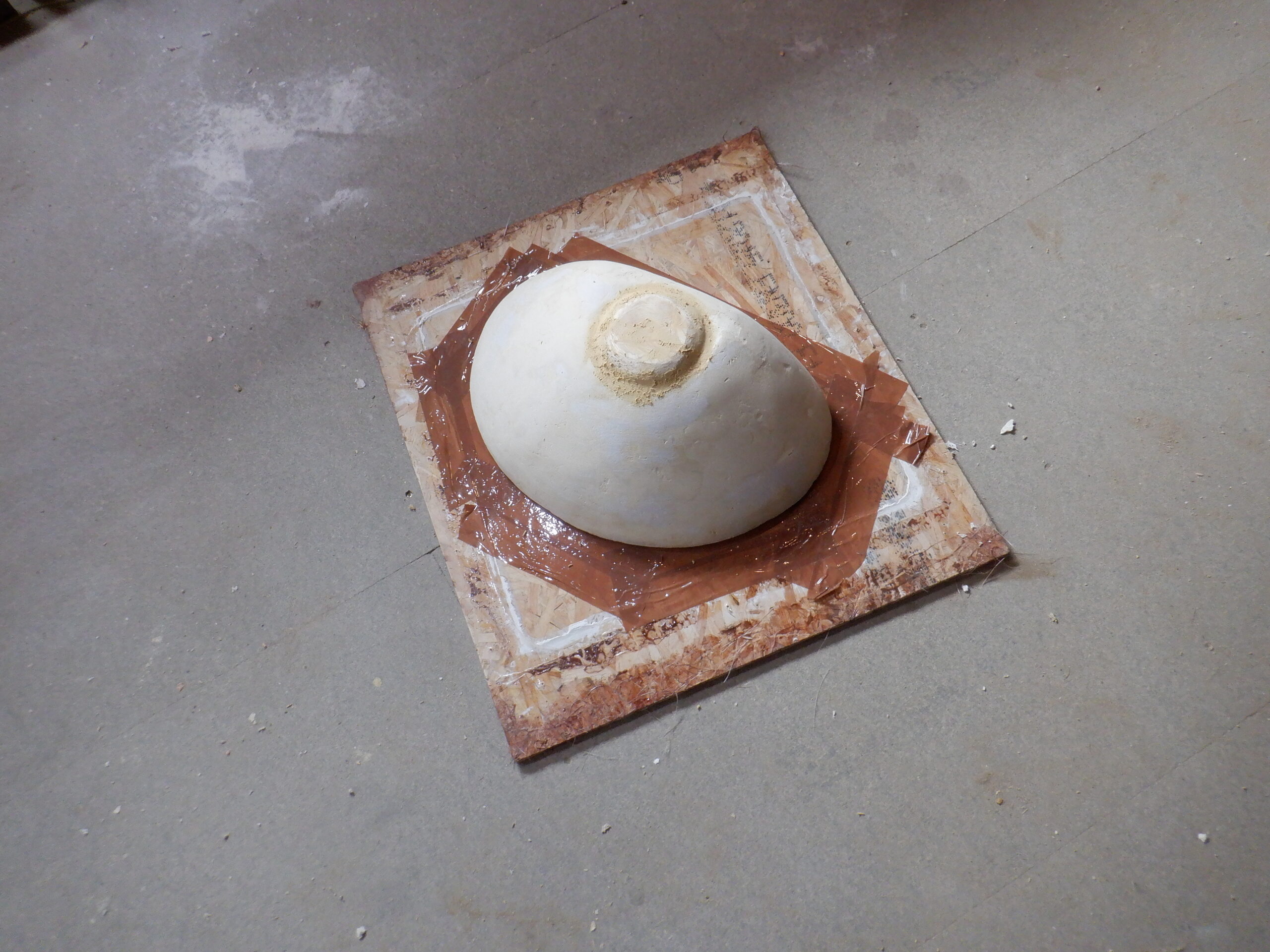
We then covered this foam layered object with two-part wood filler material, to fill in all the holes that accidentally get created and then sand it more thoroughly all over again. We repeated this process several times, patching small areas with more filler, until it was looking good.
The last piece to add to the mould, was the reinforcing drain hole layer. We will need to drill a hole in the bottom of the bowl eventually, therefore, it would be good if that area of the bowl should be reinforced with extra layers of glass fibre when we come to make the actual bowl itself. So, we found an old 100mm diameter disc and chamfered one edge with a flat 45degree slope, to make the glass fibre strands to bend and lie into the mould without sticking up. We stuck this wooden disc, which was only 11mm thick with more of the wood filler and then filled in around the edges, to make sure that it doesn’t have any “concave” hollows or pits, for the finished product to accidentally get stuck to the mould when we try taking them apart!
We noticed that the edge around the top of the bowl mould was rather jagged and we couldn’t get the wood filler to stick strongly enough so we went on to Plan B.
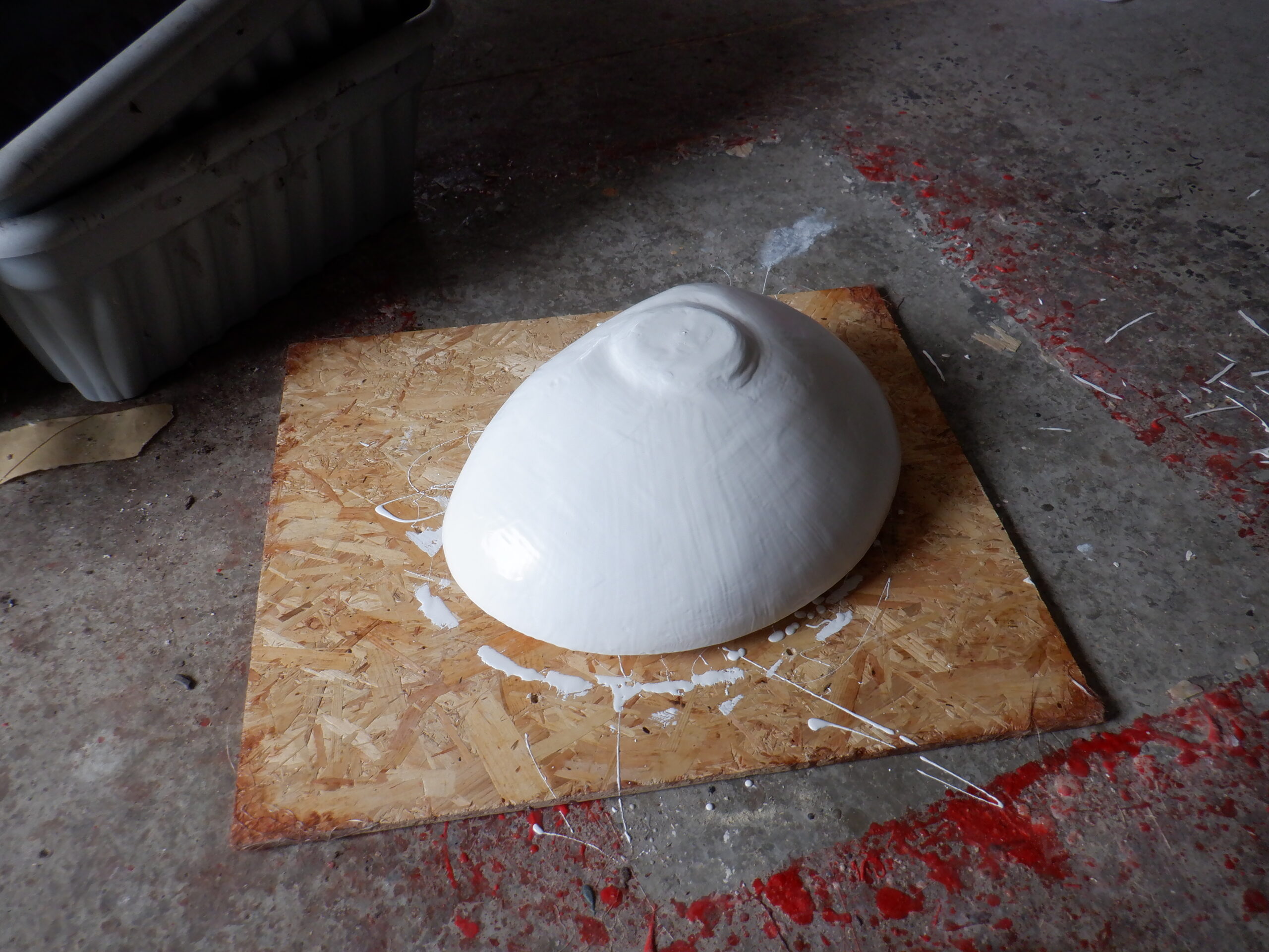
We laid the mould flat on a large smooth board with had parcel brown tape stuck to it and then covered the whole thing with Gel Coat resin and leave it to set.

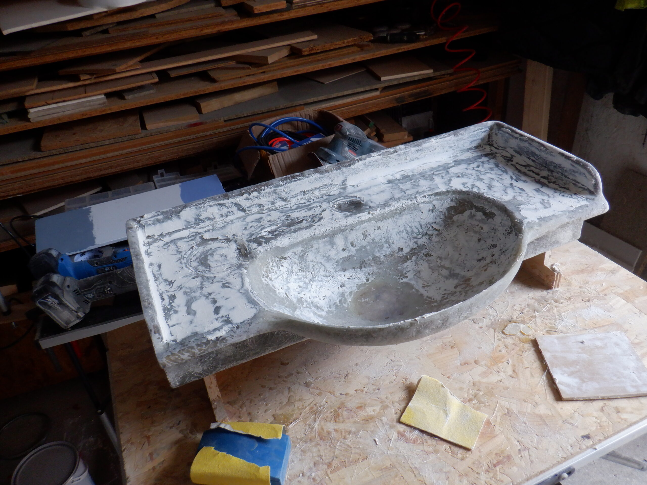
Blank filled and sanded
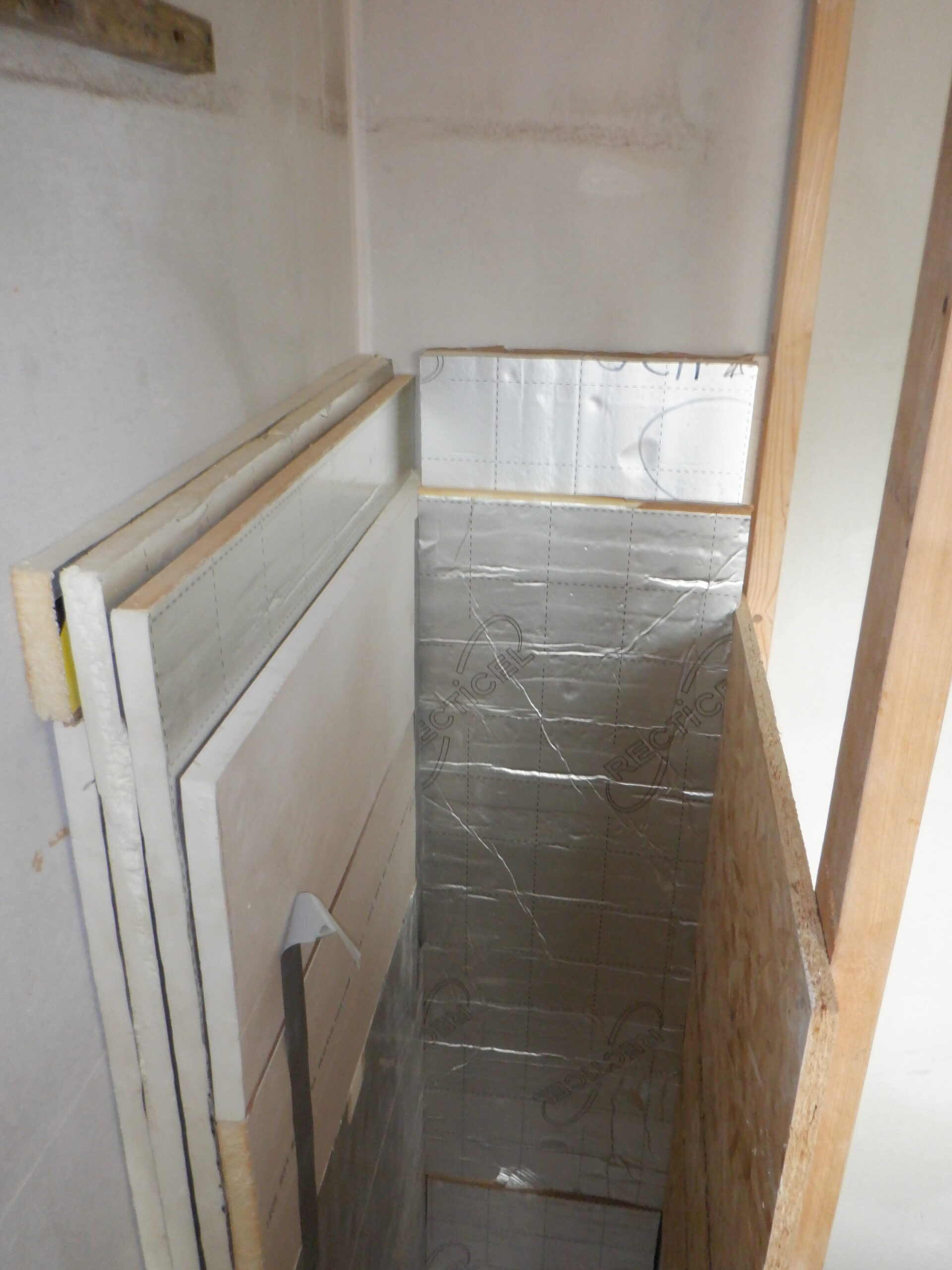
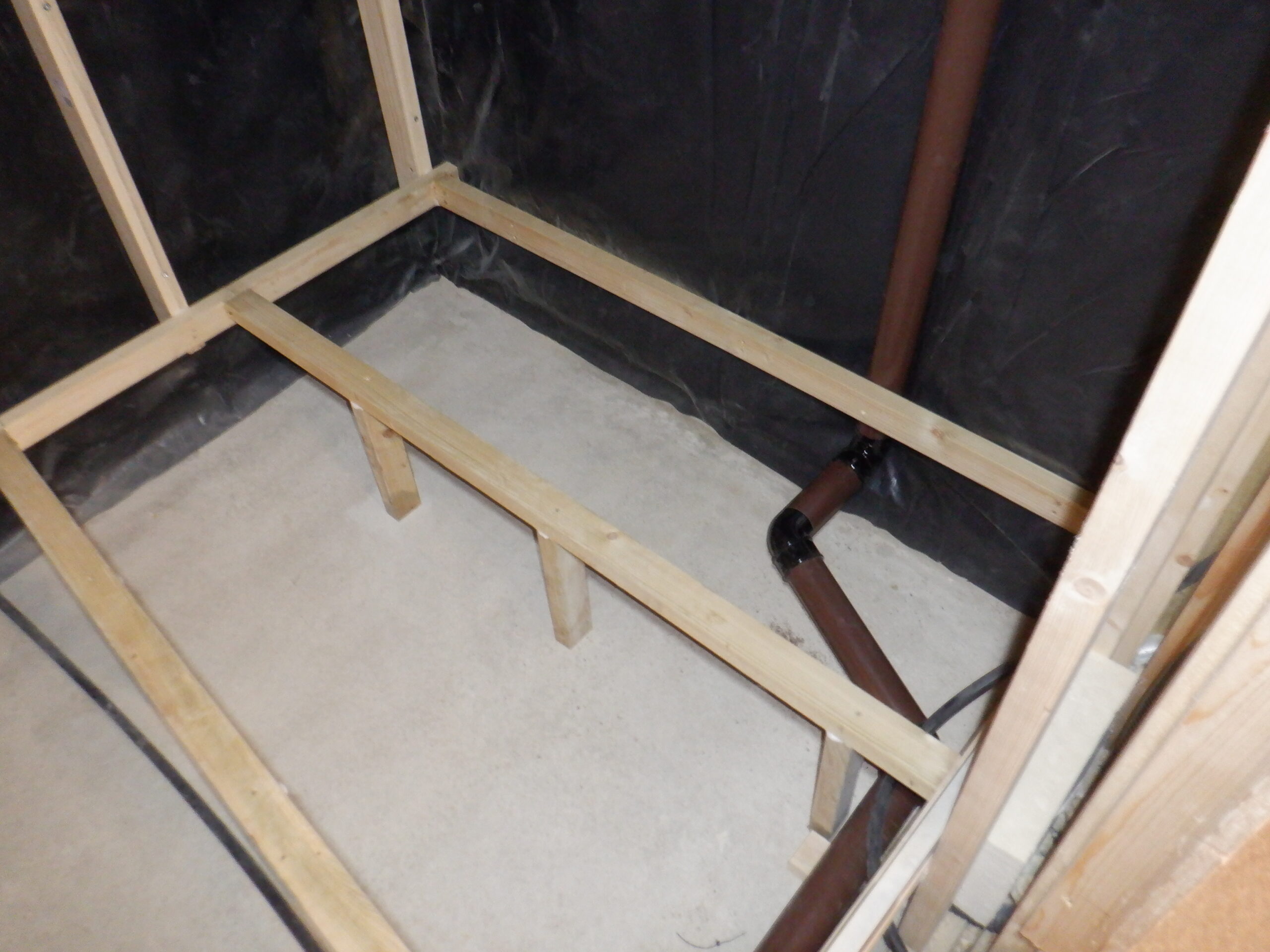
While that was setting, we got some 10mm thick cement board and sliced it up into two 300mm wide pieces. We then glued them together using PU gun foam glue and flattened them together with six 25kg concrete blocks. Next, we very carefully measured the gap in the Cloakroom where the Vanity Unit is going, into the alcove that is formed by the Linen cupboard. We needed to measure both the widths at the back and front, plus also measure the angle of the wall surfaces which turned out to be 89.6° for the left back corner, and 91.6° for the right back corner. The back width was 755mm and the front edge measured 760mm wide. So we transferred these measurements to our double thick cement board and sliced the left and right edge very carefully.
In order to help us fit this cement board “worktop” into this alcove, we got two pieces of battens and screwed them onto the wall at a point so the top surface will be at 800mm off the floor. Even though we were very careful in slicing the cement board, it still needed rasping on some parts of the left edge, to make it slide in and fit right back against the wall. We also had to rasp the two corners because they are gently curving as well.
When we carefully cut around the edge of the mould, to release it from the flat base, we noticed that there were still missing chunks around the edge, the resin is transparent so we couldn’t see how much resin there was and also we were running out of that particular batch.
We took this opportunity to install a releasing mechanism to our mould, by drilling a 6mm hole right through the middle so that we could glue in an air pipe. We also widen out the entrance to the hole, the one at the bottom of the bowl, so that when we come to glue the flexible pipe in, we will seal up the joint between the resin skin and the pipe itself.
so we stuck the mould back down again on the base (after putting more parcel tape over it) and mixed up a little bit more resin, this time adding a bit of colour, green. We blobbed a line of it all the way around the edge of the mould and also we dribbled some into our new hole to doubly make sure that the compressed air won’t “peal” off the wrong layer !!
While that coat of filler was setting, we went off to cut two more pieces of cement boards, but this time only 200mm deep, and glued them together with the same PU foam glue as before, weighted down with four concrete blocks.
Then, while we waited for that glue to set, we sliced 50mm wide strips off a 12mm thick cement board, to start making the upstand strip that will go around the edge of the vanity unit. We carefully drilled screw holes through the base board and up into the upstand pieces. We had to replace one piece because we didn’t drill out the pilot hole wide enough to allow the screw to go in without breaking the hard cement strip apart. We were successful the second time around after testing various sizes. It needed a 3mm pilot hole and a 3.5mm clearance hole, to allow the 40mm long 3.5mm wide screw to go in fully.
By this time, the glue had set so we got our 200mm wide strip and place on top the other base board, because the same shape and size also fitted very well at the lower shelf position. So, we placed the larger piece on top of the 200mm piece and sliced off the excess ends. We rounded the back two corners, just like the base board and both of them slid into place very neatly.
We positioned the batten for the lower shelf so it just sat slightly higher than the waste drain hole going through the side wall. We drilled a clearance large hole through the batten and then screwed the two pieces on to the wall. We decided that we only needed two of them, a left one and a right one only.
We then painted them the same grey colour as the rest of the wall. We did the other battens for the main vanity unit as well.
One of the last things we did at the end of one of our days doing this job, was to finish filling in the mould around the edge with the wood filler. We now can get that nice and smooth and we had enough time at the end of the day, to coat a final top-coat resin all over and let it set overnight.
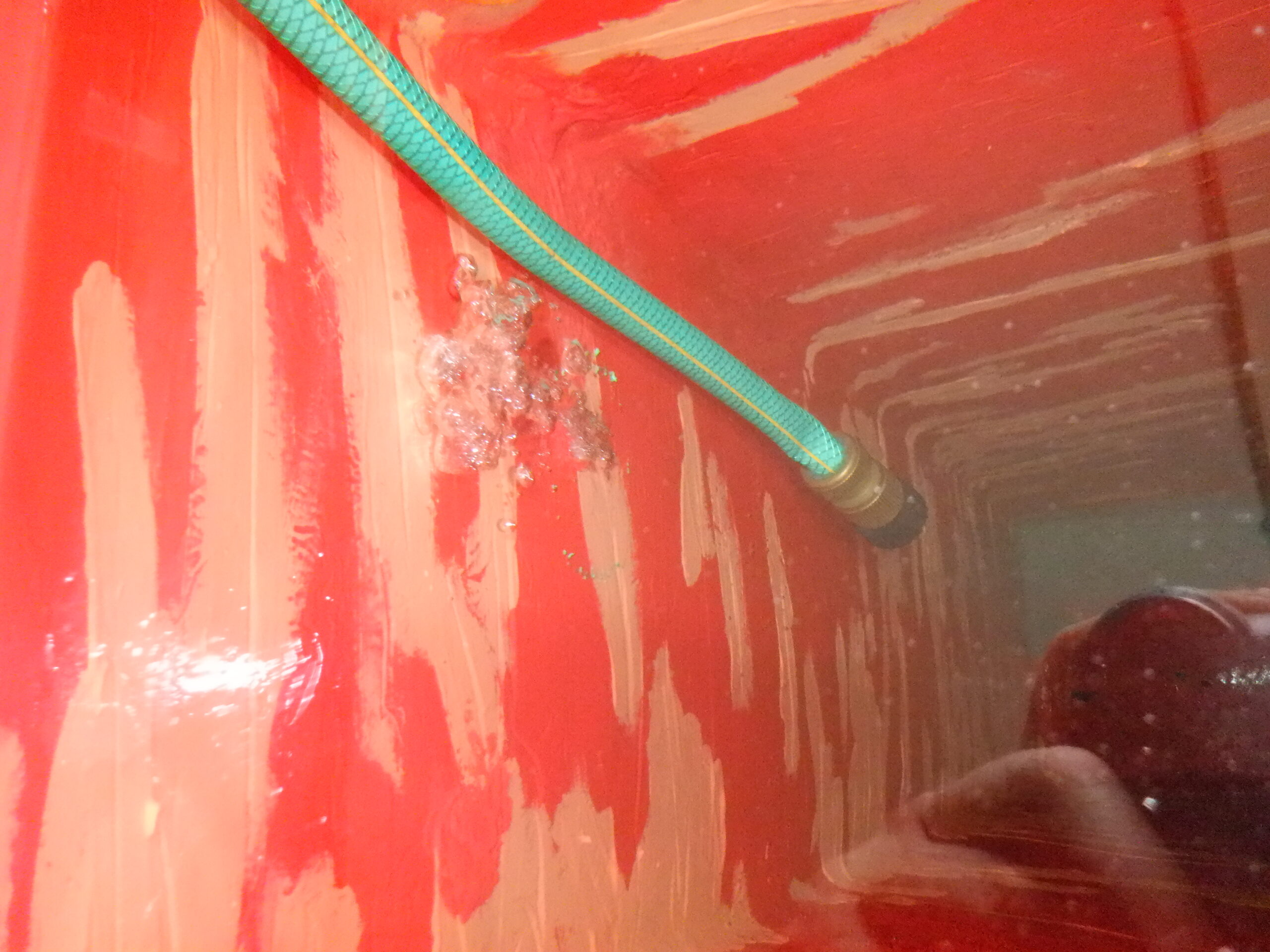
Upon the following day, we trimmed off the various drip marks hanging off the bottom of the mould and then proceeded to polish the mould with layers and layers of wax. We had a special tin of wax release substance that is especially designed for glass fibre resin production where the wax is put on to the mould so that the resin cannot stick to it and should pop off fairly easily .. we hope !!
We put on six layers in total, each layer needing 15minutes for the wax to dry before applying the next layer.
While we waited, we got on with another task of shaping the 50mm wide upstand pieces that we previously have cut and screwed. We put on a 50mm radius curves on the beginning of the two side upstands, and then, routed a quarter round on the front edge of all four upstand pieces. We continued to use this quarter round cutter to trim the front edge of the flat top of the vanity unit, on both top edge and bottom edge, to form a bull nose profile. We also did the same to the lower shelf as well.
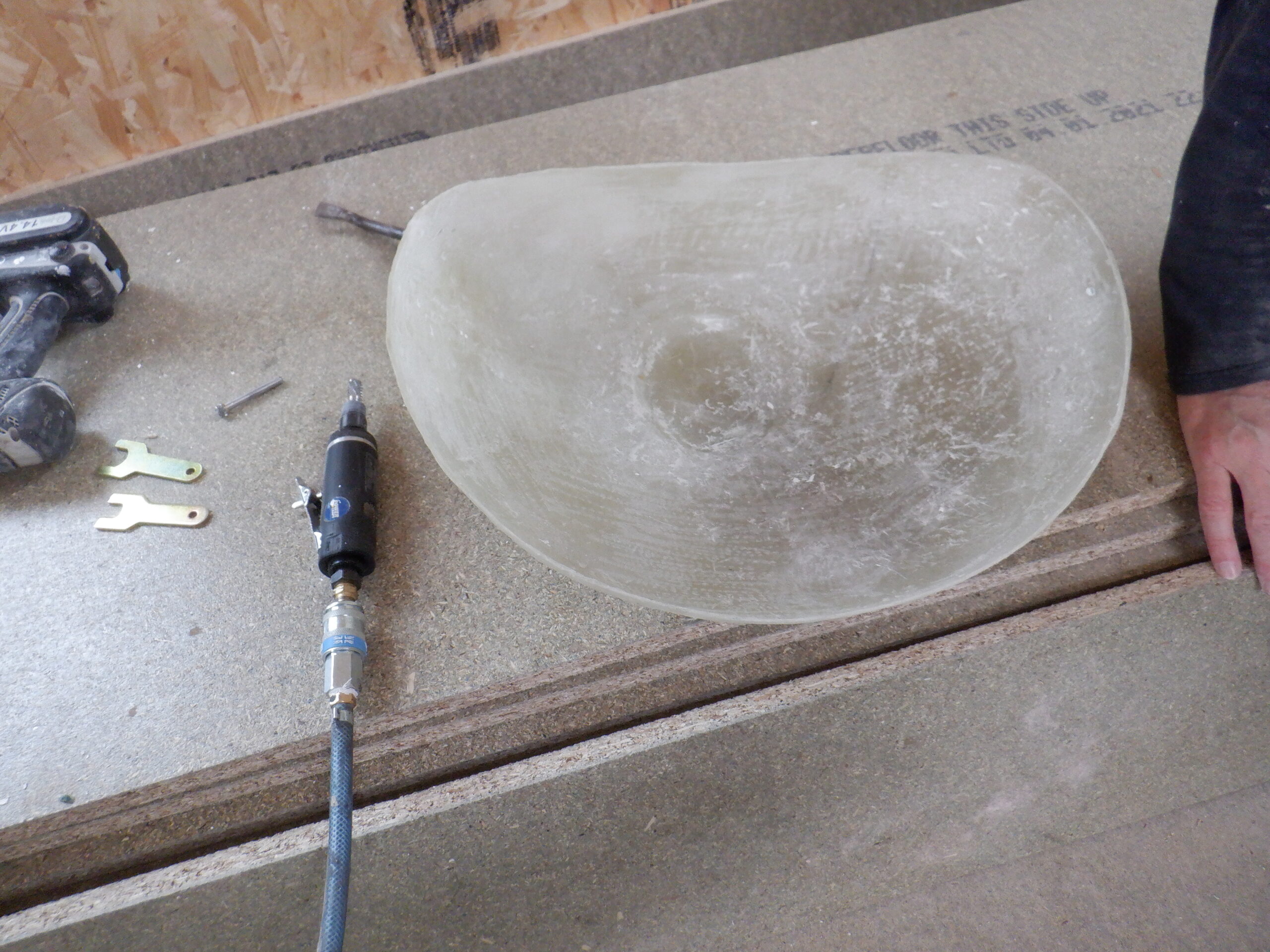
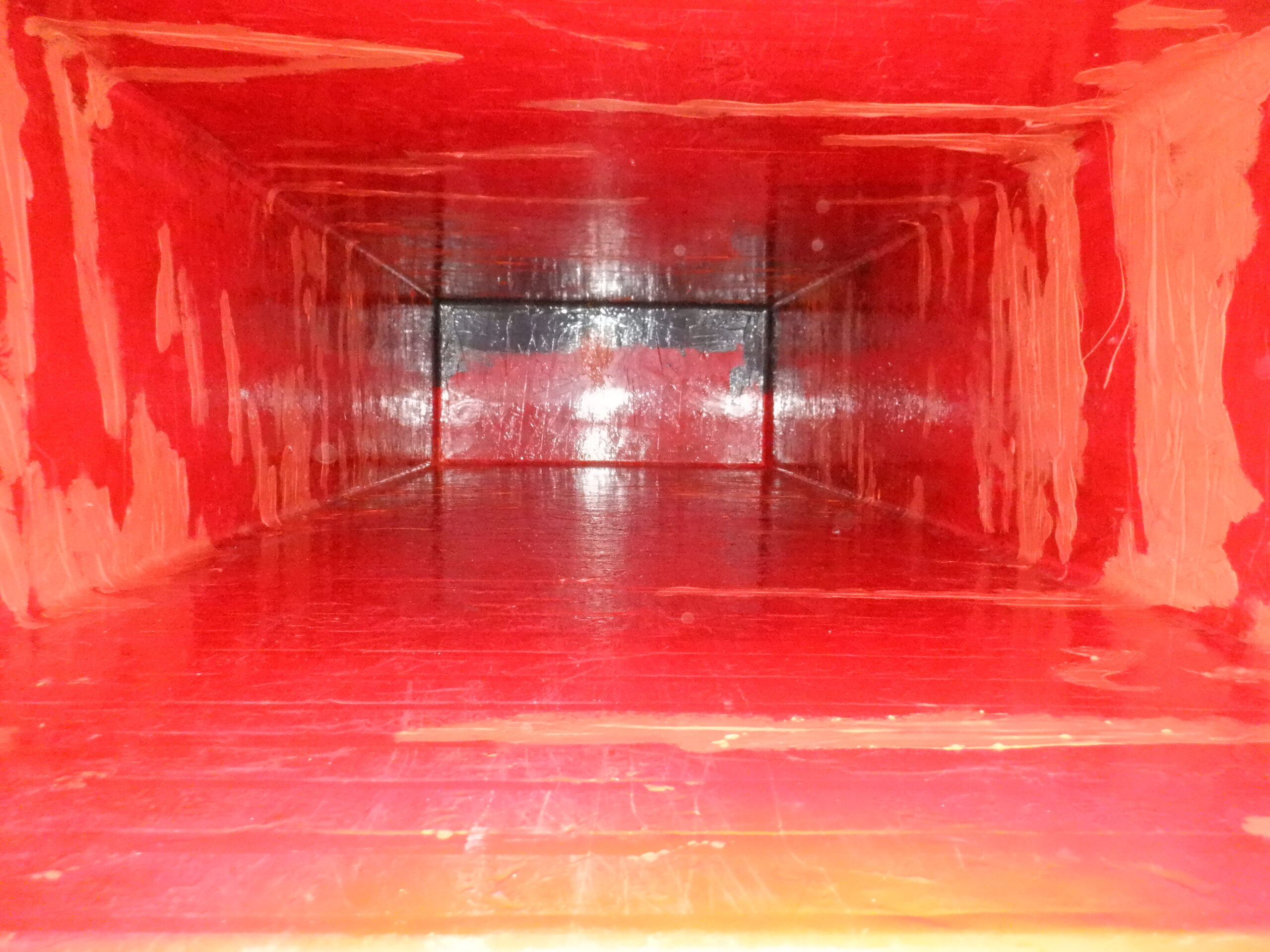
Now, we dived into the deep end and went ahead to cover our basin mould with three layers of glass fibre, with regular resin on each layer, and allowed it to cure and harden.
We then trimmed the dangling “curtain” of glass fibre off the bottom of the mould, tidied up the edge

Bowl with initial fibreglass layers
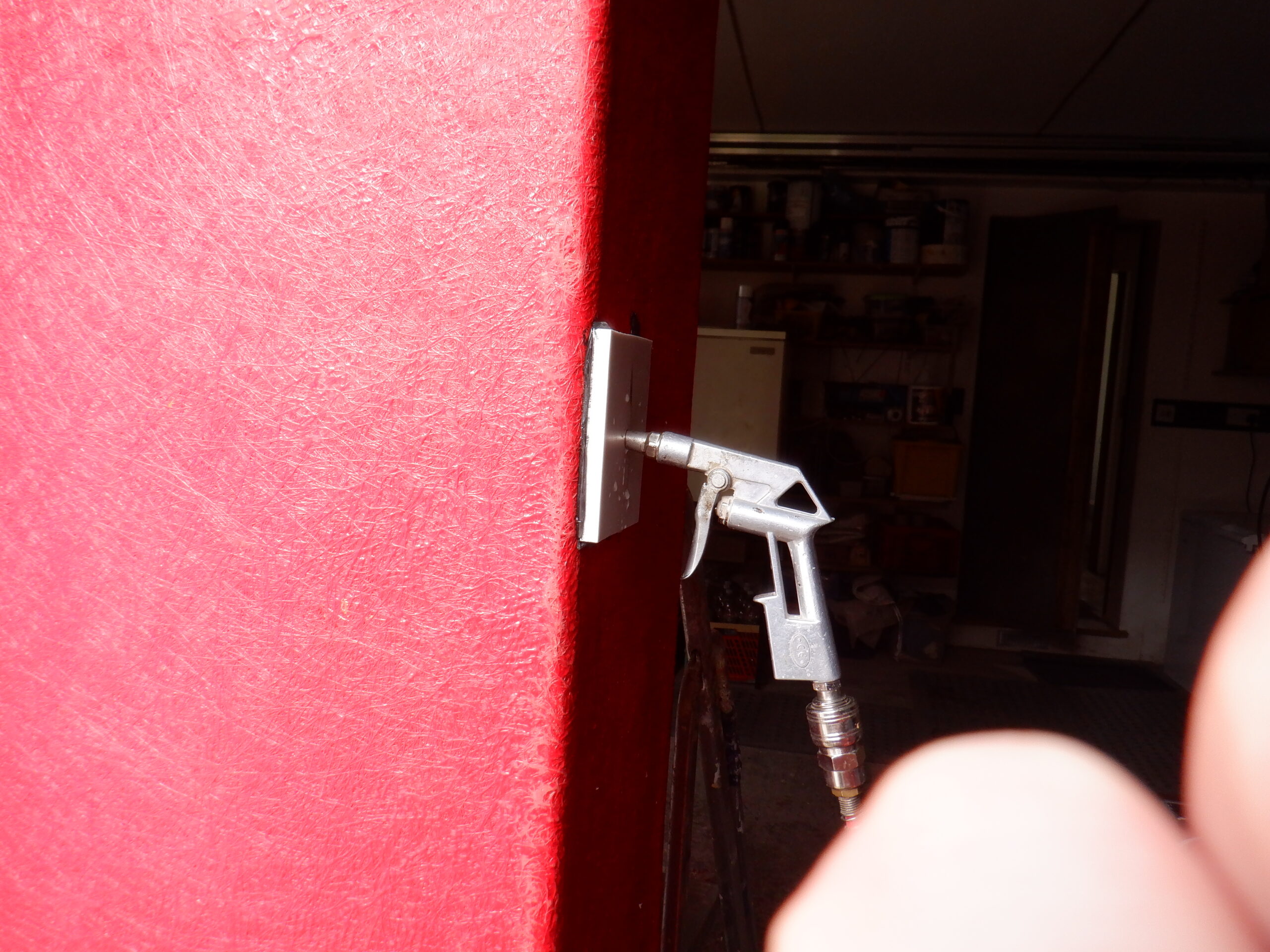
Then we attempted to “blow-off” the finished basin off the mould by squirting in compressed air down the air pipe we had installed .. but .. alas .. it didn’t work!! OOOO Boy!
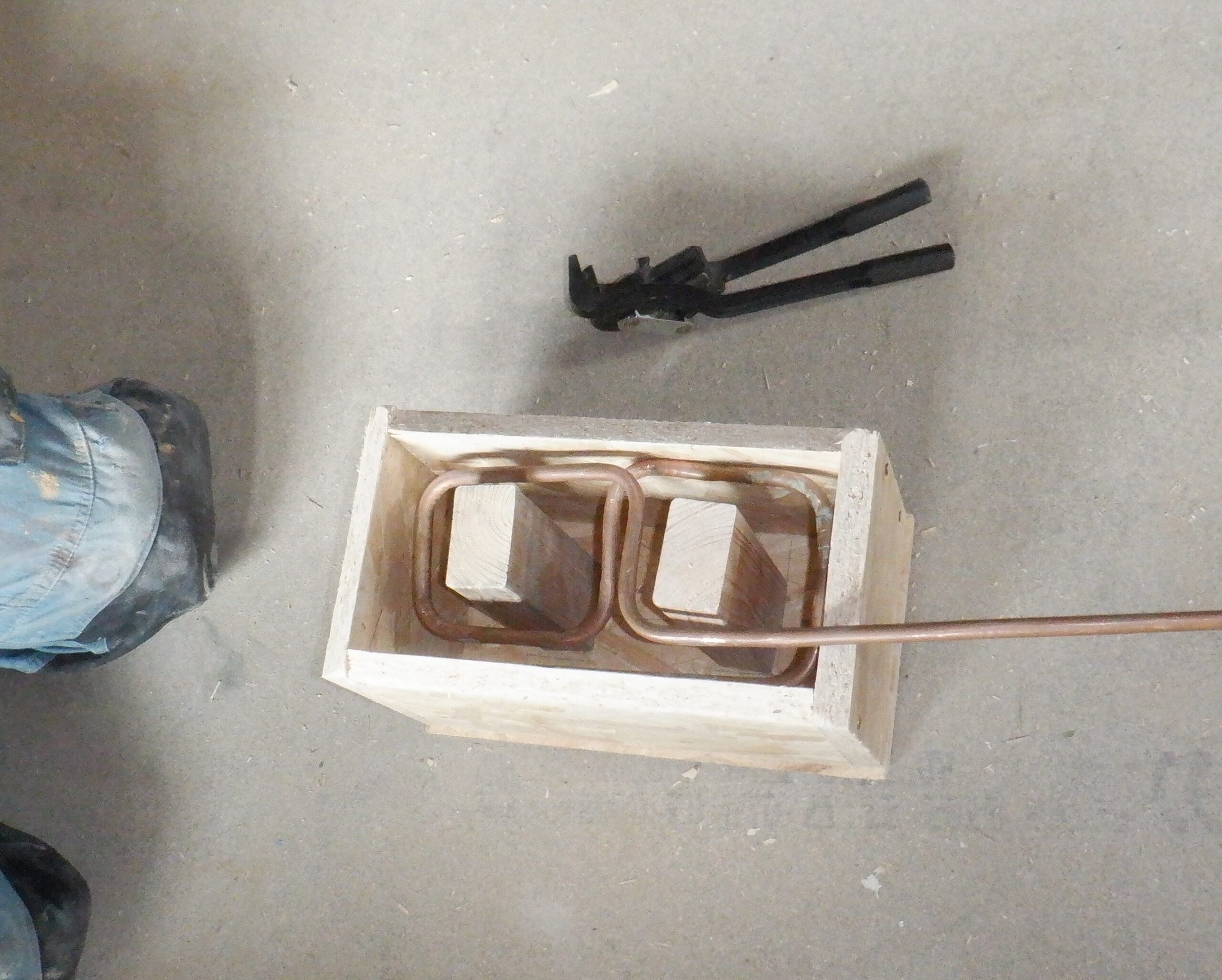
We tried to jam two crowbars deep into the foam base of the mould, tied some string between them and tried yanking the mould off .. but .. alas .. NO Joy! It broke the foam material.
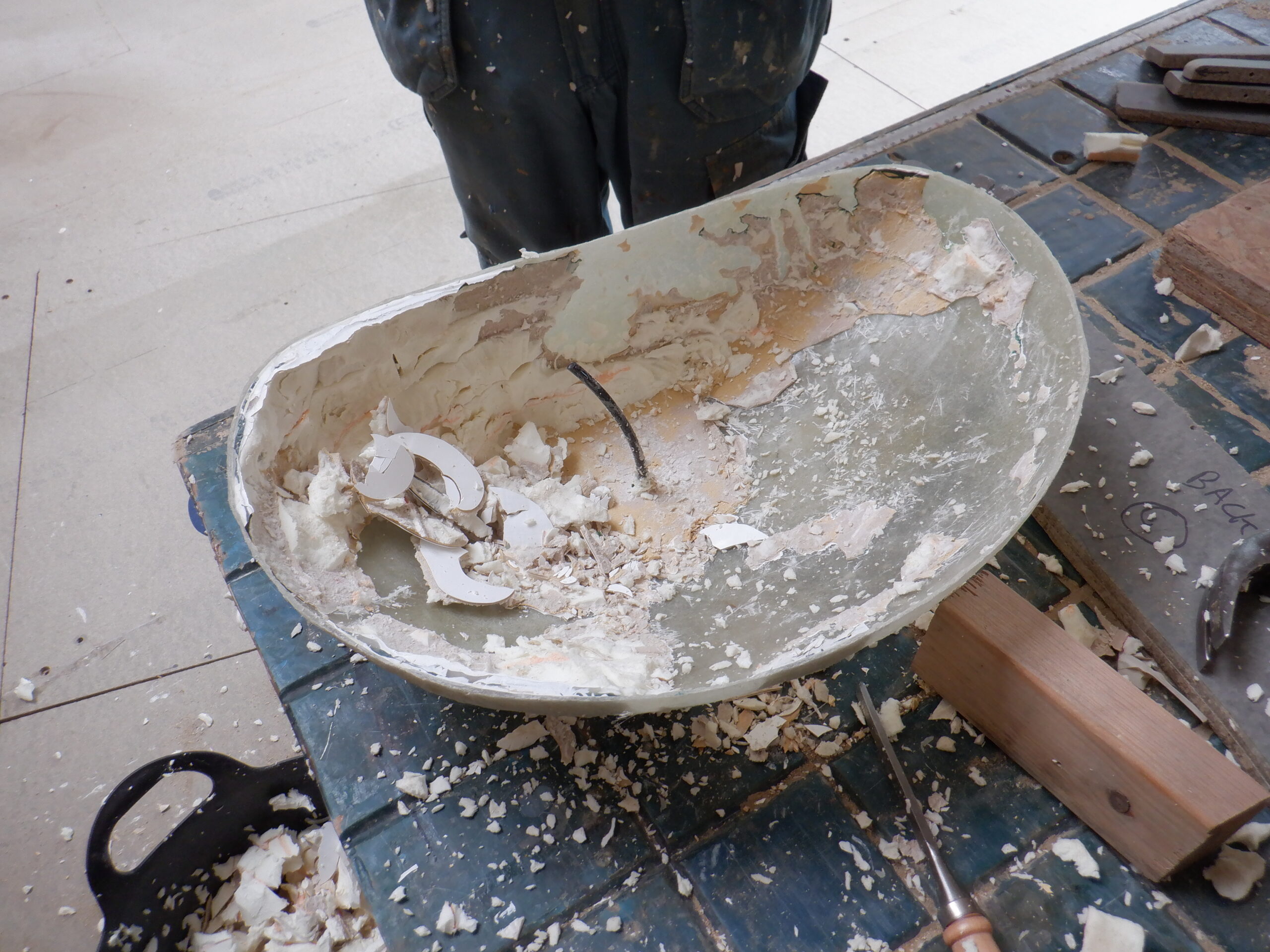
This meant that we had to destroy our lovely mould! We hacked out all the foam and started nibbling the inner mould layer. It seems that the glass fibre basin part had stuck to our mould in several places, hence why we couldn’t release the mould. It seems that the waxing process didn’t do a complete coverage all over the mould. We are not sure to why. Phew!!
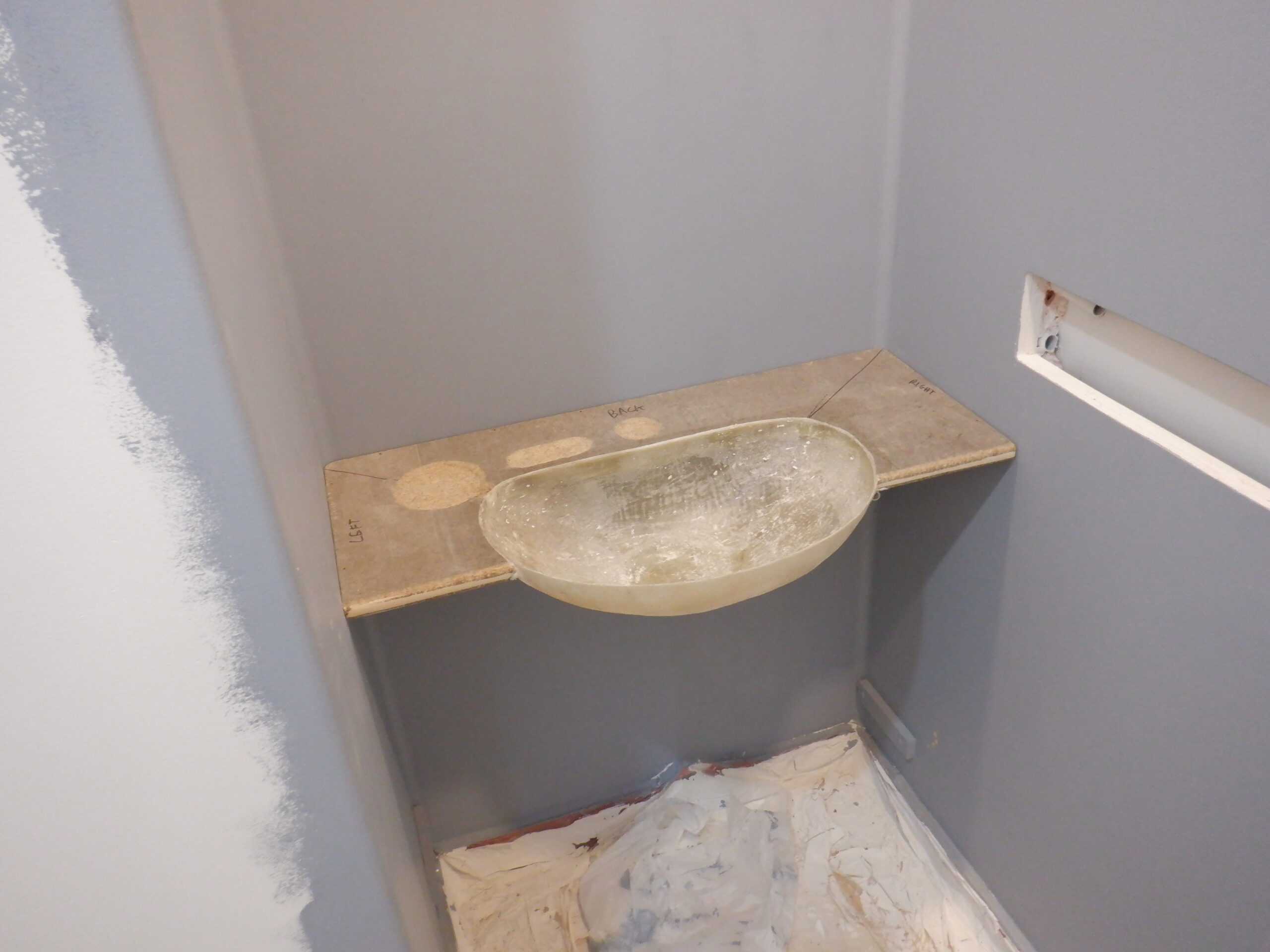
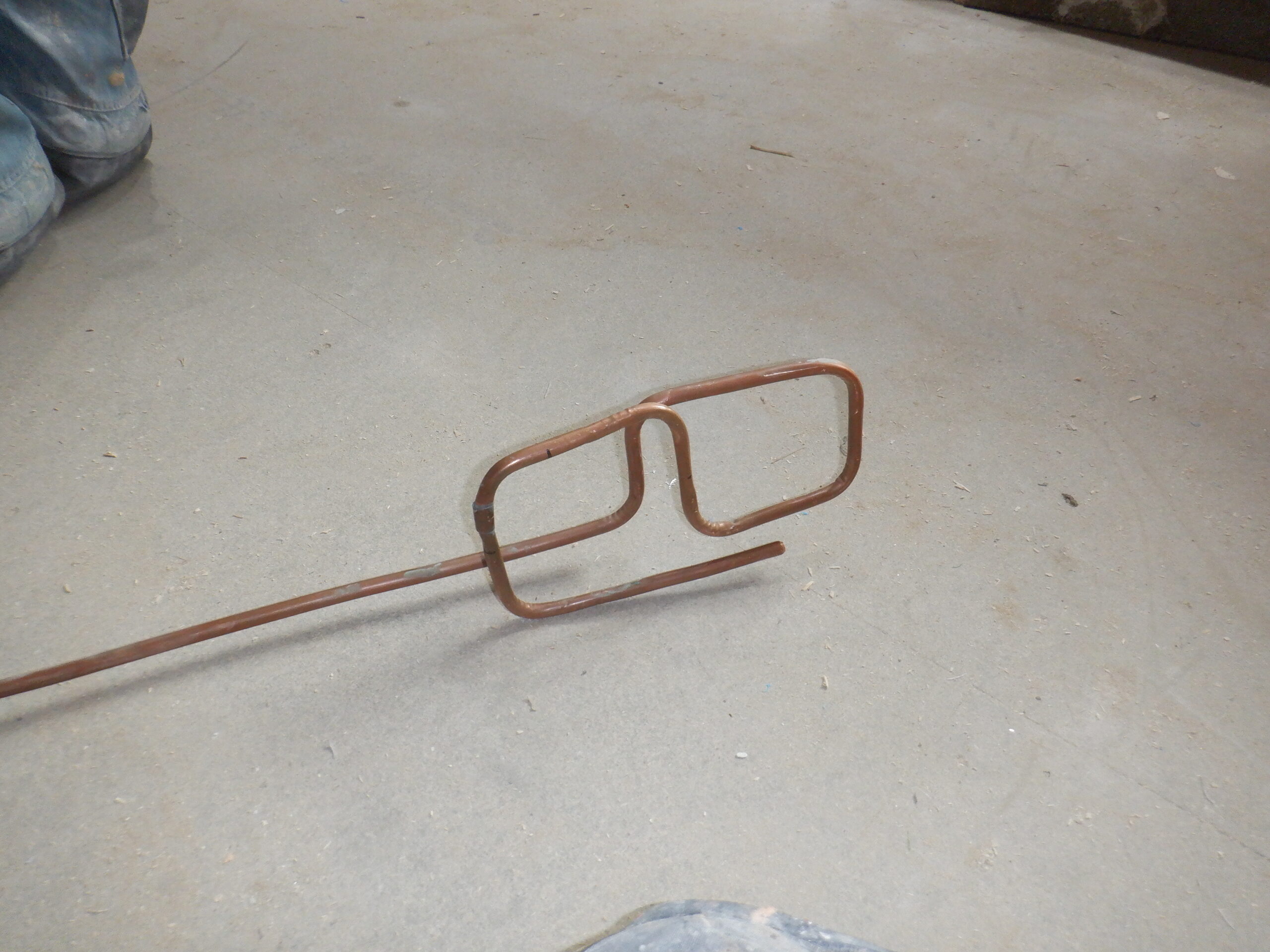
It took us several hours to rip the foam stuff out and then carefully, chip away the thin layer of resin from the basin bowl. We ended up with a couple of spots that needed grinding to remove the excess material. We eventually got our basin bowl out of it .. But, we will have to make another mould for the other wet rooms that contains a vanity unit with a basin. Phew!

Struggling to remove the foam plug

Cleaned up!
Now, we can mark out the cut out shape for the bowl, on the cement base board of our Vanity Unit, and proceeded to cut the piece so we ended up with the bowl fitting snuggly into place. We blunted the blade on the jigsaw as it is very hard cement material.
Now that we have a boundary between the flat surface of the vanity unit and the bowl, we now can position the locations for the soap depression, plus also for the nail brush and the plug itself. We set up the router to use a hemisphere cutter bit and using a pre-made template (a piece of 6mm MDF board with a 100mm circle for the soap dish, an oval elongated shape for the nail brush and a smaller round one for the plug) and carefully cut away the cement material until we had three depressions, neatly arranged around the edge of the basin bowl, starting on the left hand side and finishing with the plug depression centred, above the overflow outlet and the drain hole. There would be room for a bottle of liquid soap and then finally, the spout itself to give a gentle fountain of water etc.
We then glued the basin bowl into the cut out zone of the cement base board, using lots of PU construction glue which is very sticky and very tough once it is set. We left it 24 hours to cure and harden. We stuck a couple of bricks on top to hold down the bowl (which is upside down) sitting on our work table.

Glued in the top
Then, we proceeded to put a little vertical piece of the same cement sandwich board we had left-over, to form a little barrier just under the front edge of the vanity unit and connects to the curve of the bowl. We did this on both left- and right- and sides. We use a small piece of 20mm wooden batten to help secure these pieces into place and then we put a gentle quarter round on the lower edge to remove any sharp edges, before we continued to glue these two pieces into place using 5minutes PU glue, we also stuck down the four pieces of our upstand that goes around the edge of the work top.
It is getting there .. !
The next task is to fill in all the corners with two-part resin base filler, to smooth the transition on all the joints, to provide a curve so that the glass fibre can be encouraged to bend around the corners without breaking, or popping clear of the resin before it had set.
While we remembered, one of the final use of the router, was to cut another quarter round on the edge of the basin bowl that is touching the cement work top, again to allow the glass fibre to bend down into the bowl itself.
We put in more filler around the upstand and use a 22mm tube to form a curved profile on all the 90degree corners and that was rubbed down smooth.
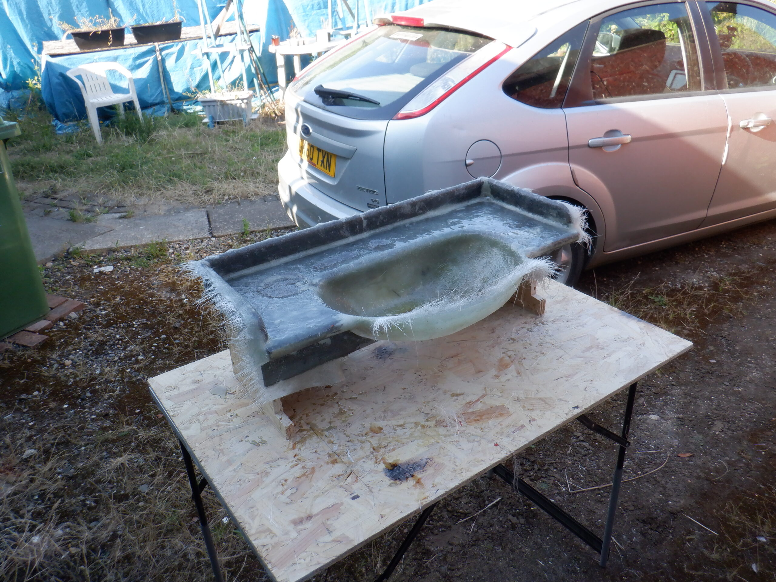
We built a little “stand” to hold the vanity unit up and clear off the table so we can apply the fibre glass and resin all over, without sticking to the table etc.
So, after rubbing down all the fillings, we blasted the whole thing with compressed air and move this and the stand to the Garage and stuck on two layers of glass fibre with resin all over the top surface and bowl.

Fibreglassed all over
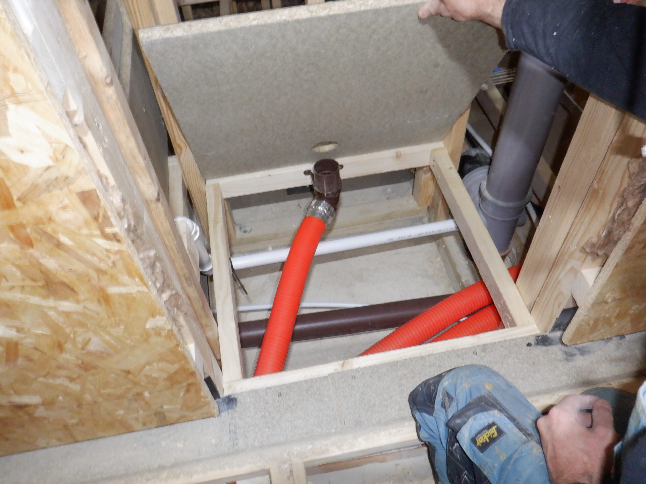
While that was curing, we got the second shelf and drilled a large clearance hole at the back of the shelf, centred. It is a 50mm wide hole to allow the push fit plumbing right angle connector up underneath so it can receive the waste pipe coming down from the trap and the bottom of the bowl itself. We then made a quick and easy legs to hold up the shelf, using two small pieces of OSB and carefully screwed two long screws on each narrow ends of the shelf, through a small piece of plastic pipe to act as a spacer. The whole thing held the shelf well clear of the table.
Upon the following day, We then trimmed off all the sticking out straggling strands of glass fibre and turned over the whole thing so we could resin and apply more fibre glass underneath the vanity unit and especially doing the front half of the bowl, to strengthen it so it will be much stronger and resistance to being bumped into in the Cloakroom.
While that was setting, we also did the second shelf and we covered it in glass fibre in one go, doing both sides at the same time, including going over the drain hole as well.

Lower shelf resin coated
After lunch, We proceeded to trimmed all the loose strands off both the vanity unit and the second shelf. Then rub all over everywhere and we put in extra filler here and there, to touch up areas that became a bit too thin after sanding the lumps away. We also thickened up the edge around the bowl and filling in air gaps that accidentally formed during the second stage of putting glass fibre on. We also decided to put the white filler on all the flat surface, to help remove much of the gently wavy surface.

All filled and sanded
At this point, we are reaching the moment where we need to apply the final colouring layers, but, we do need various plumbing bits and pieces, like the over-flow and the drain hole, to come from our suppliers.
So, in the meantime, while we waited for our plumbing order to arrive, we got on with colouring up the second shelf, with the final dark grey with a hint of blue in it. We also collected up a collection of tiny pieces of glitter of various colours, sieving out all the larger lumps. We put the shelf back on the support stand so that we could coat both sides in one go. We mixed 200g of the grey / blue mixture we previously settled on. We experimented with lots of different shades of greys and different levels of blues as well
And we settled on this darker shade of grey and were happy with the blue content as well.
So we coated the second shelf with the grey colour and while it is still tacky, carefully sprinkled on our tiny pieces of glitter all over, on both sides of the shelf. Then, later on, several hours later, we applied a protective clear coat of resin which is designed to help seal everything in and provide a very smooth finish.
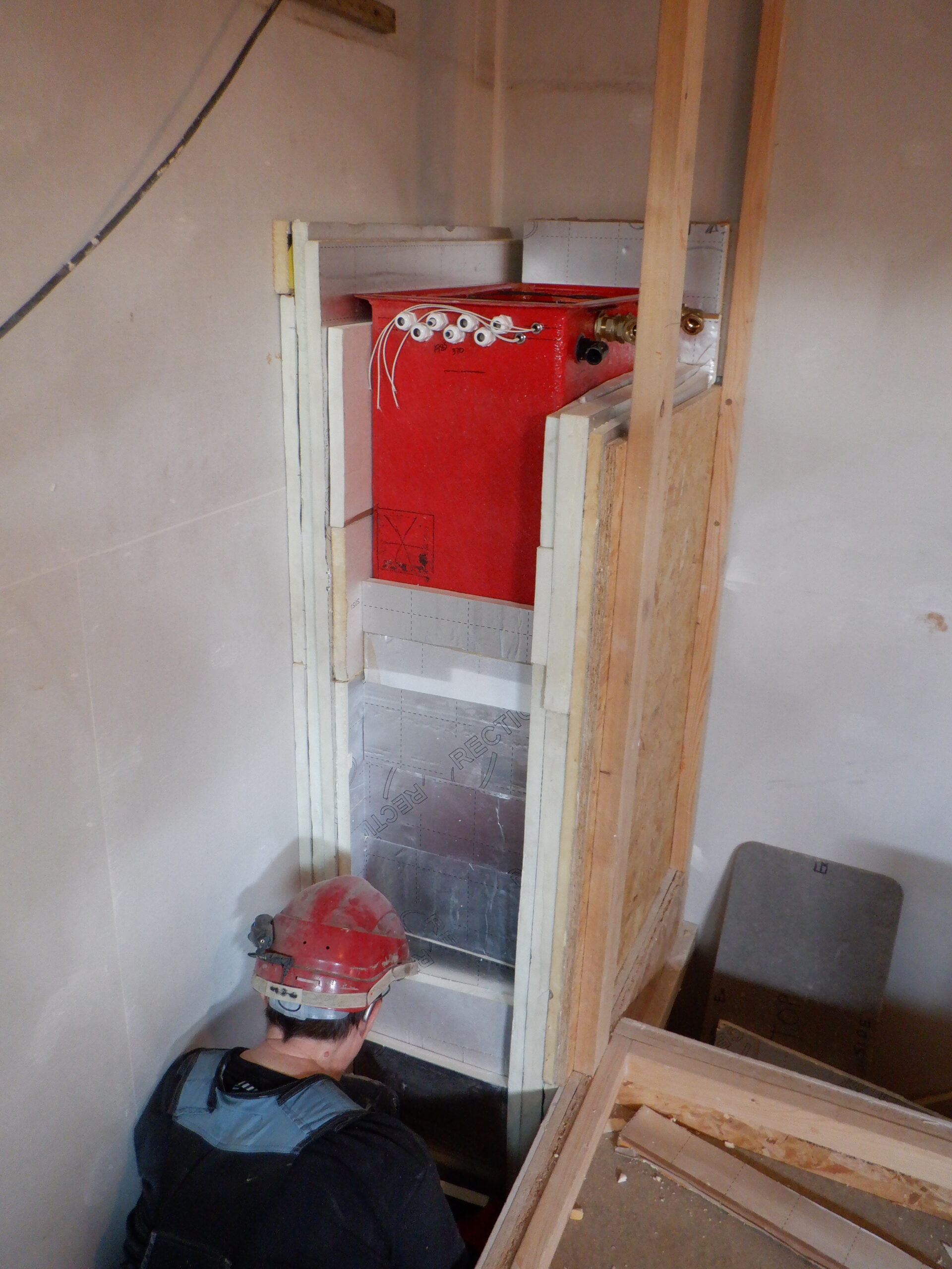
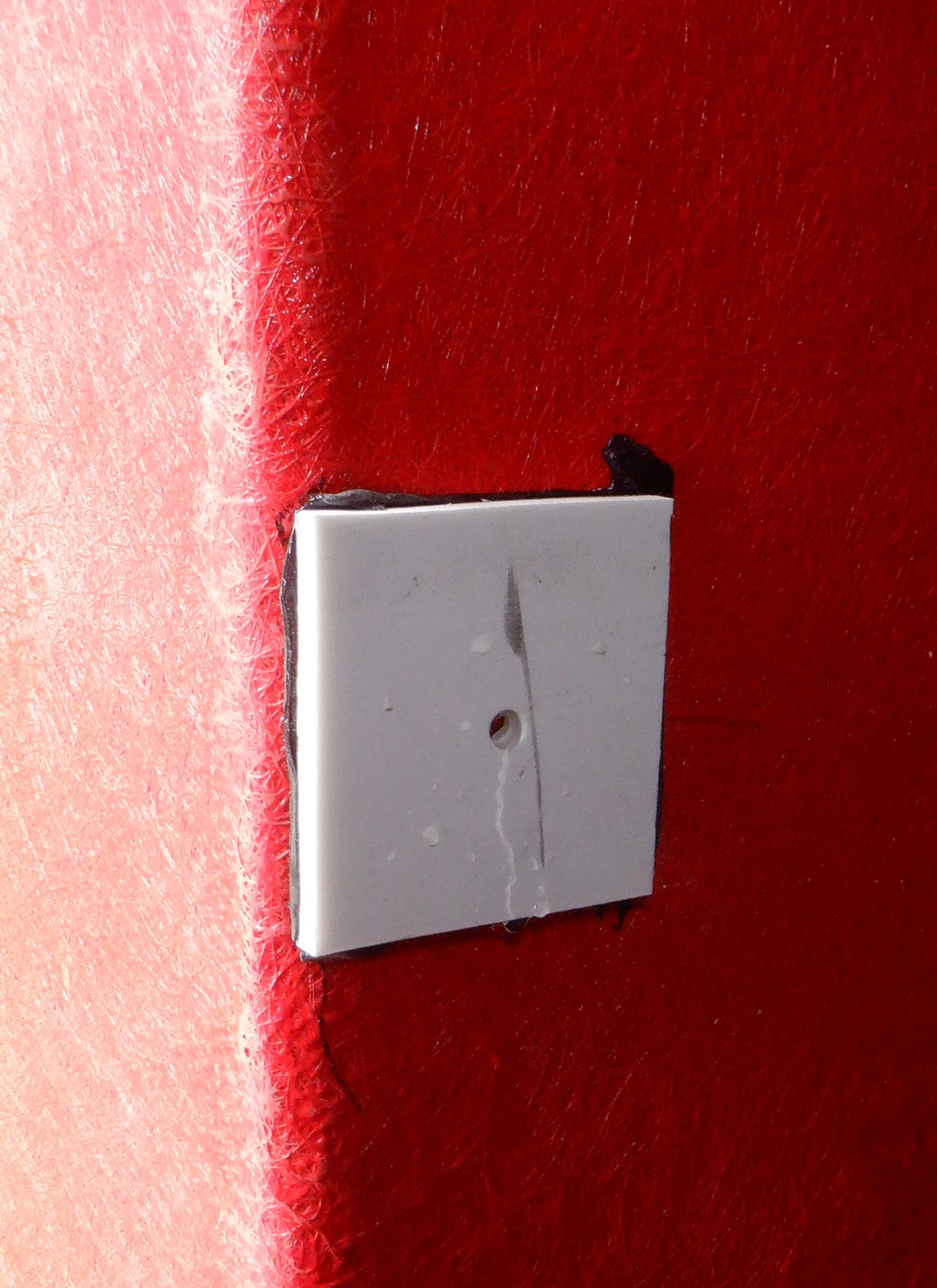
By now, our plumbing items arrives, a over-flow plastic pipe so we drilled a new hole into our basin bowl, just below the rim, using a core drill of 27mm diameter and then digging out a little bit of the cement board underneath and behind the bowl. We then glued this plastic right angle pipe in with lots of the plastic filler, covering up the threaded part and over the flange at the back, and squashing it all together by using the nut to push the filler tight into the thread and the surrounding area. After it had set, we sliced off the plastic nut and the remaining pipe that was sticking out into the bowl area. We sanded it smooth and then touched up some small hollow bits until we got it lovely and smooth.
The next job was to install the drain hole and plug. It measures 41mm across on the threaded section and the flange is 61mm across. So, we used a 44mm core drill but we added an extra piece of wood, cut into a circle, a piece of 3mm thick plywood, also cut to a 61mm circle and positioned it behind the core drill bit. We stuck on a small piece of 60grit sandpaper on the wooden disc and then locked the core drill on to its holder. We then got a middle position in the bottom of the basin bowl and drilled through the thick layers of glass fibre and resin material from underneath first, then turning over the whole thing, continued to cut the remainder of the hole from the bowl side downwards. Then, we did continue grinding the surface away using the little sanding disc we had attached so it created a little hollow for the flange of the drain hole to sit neatly into place and just be below the surface. We chamfered the hole a little bit to allow the plastic moulded drain hole unit to fit in better etc.
We then trimmed down the long threaded part so there was just enough thread left to attach a solvent weld adapter to let us fit a right angle 32mm waste pipe piece, to bring the waste pipe back towards the wall and then turn to go down towards the second shelf and the large clearance hole we have already made.
The last thing we did for this particular day, is to coat the grey / blue gel coat on to the under side of the vanity unit all over and then sprinkle our glitter everywhere. We used a small fan to provide a gentle wind to blow the glitter up onto the vertical surfaces. We have just been holding up a pinch of the sparkles about 2 feet above the target area and sprinkle it that way. but, that doesn’t work so well for vertical surfaces so we used a little fan instead.
Upon the next day, an interrupted day with a external meeting to attend, we put on the final glossy top-coat resin on to the back half of the vanity unit (it is still upside-down) because the grey resin is very slightly tacky and we felt that turning it over wouldn’t be a good idea without causing problems like getting stuck etc. So, the top-coat went on to cover up the grey and provides a very hard finish.
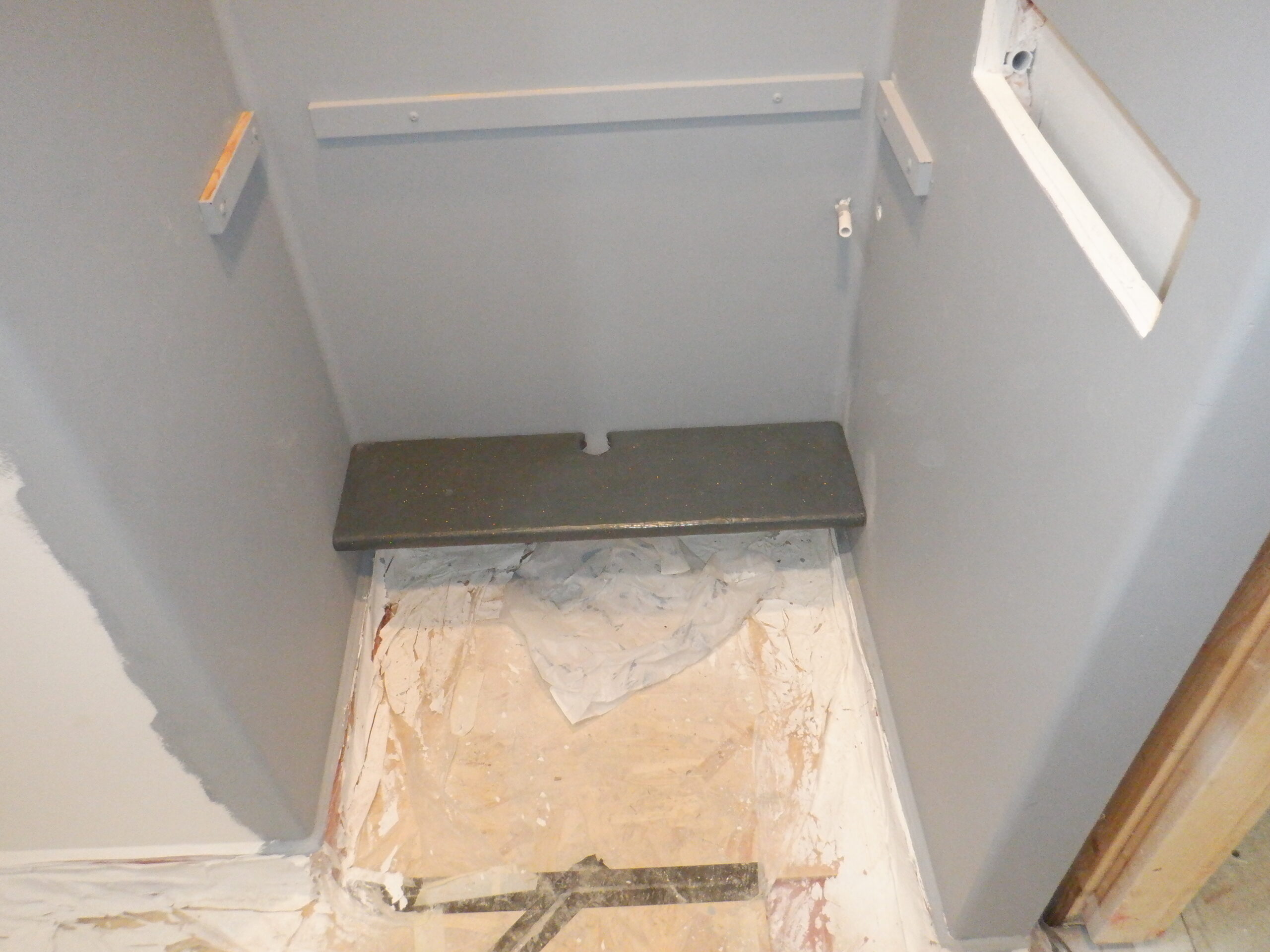
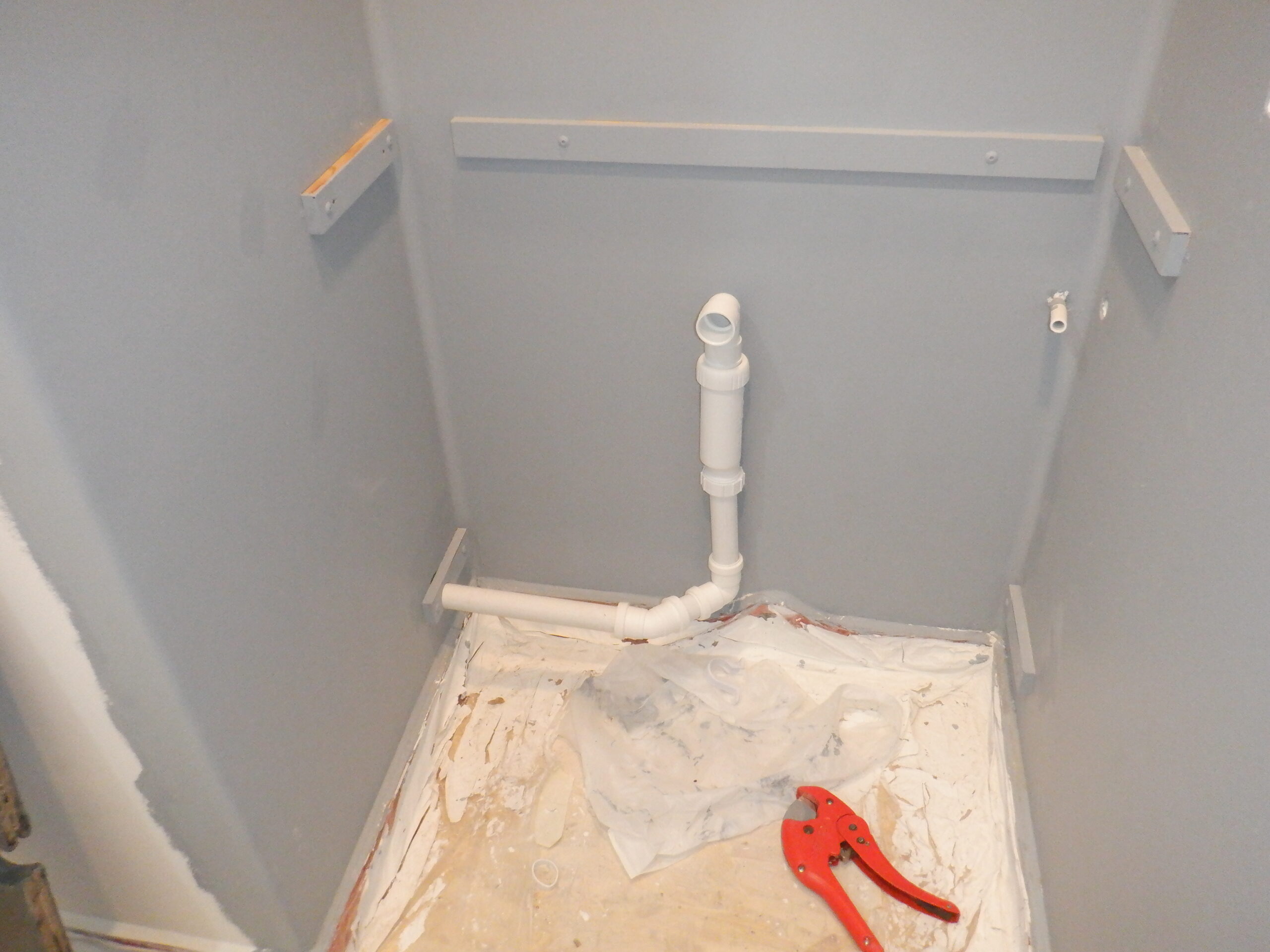
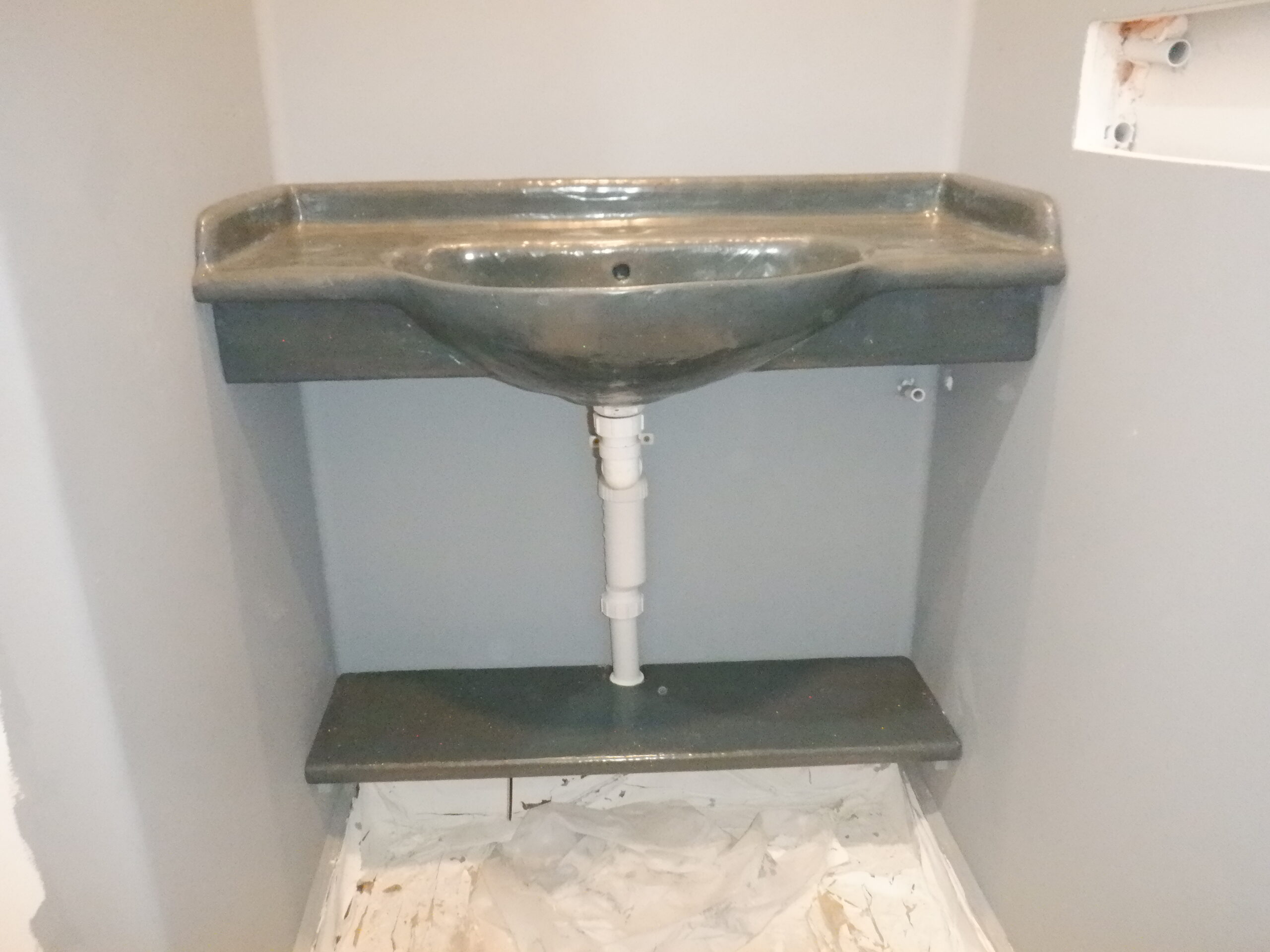
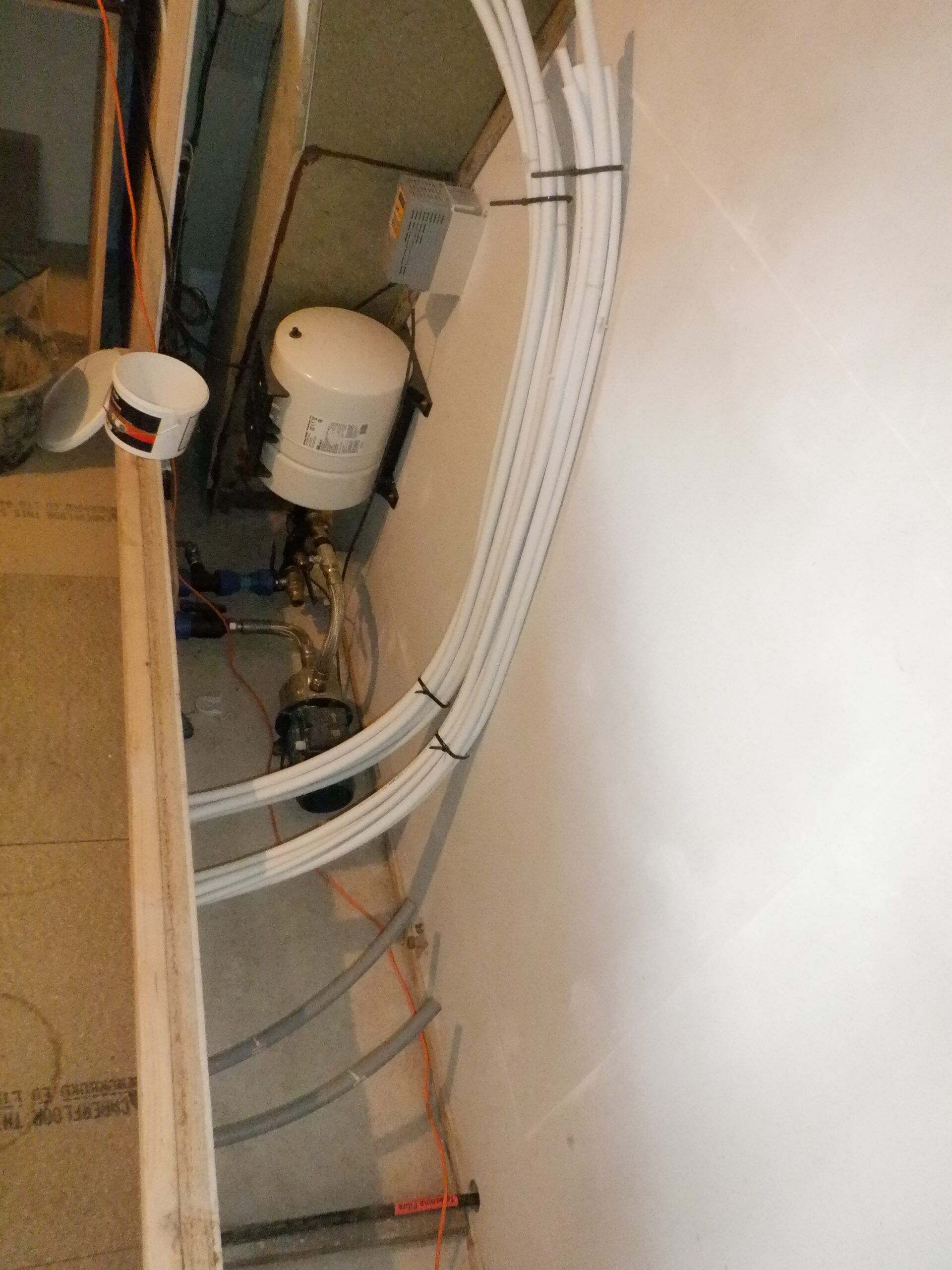
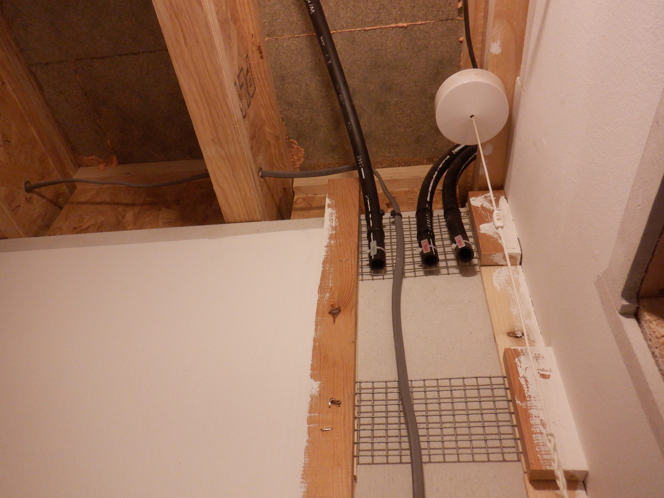
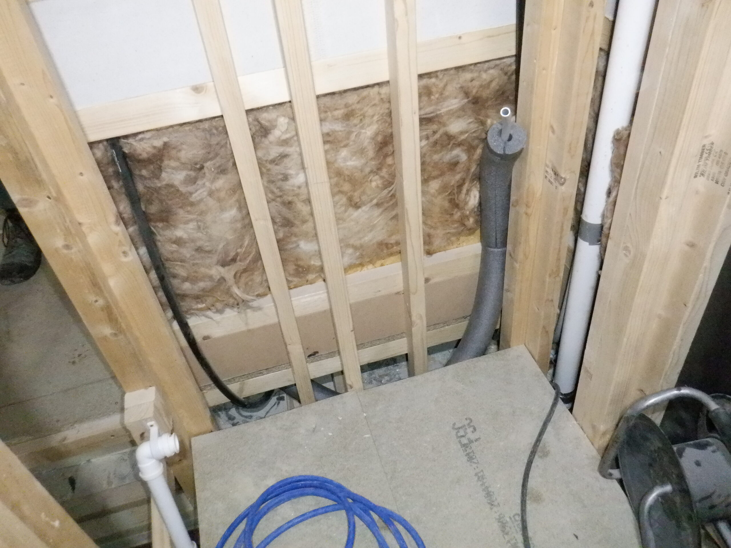
We had a little bit of time before lunch so we took our finished second shelf, cleaned off all the dribbles around the back edges and fitted it in our Cloakroom. Well, not actually fitted exactly, I mean, with glue and everything! Just resting there on the support battens so we can sort out the waste plumbing pipes that will be coming down from the bowl. We are using push-fit plumbing parts, to take the waste water through the trap (which is above the shelf) and then turns a right angle immediately underneath the shelf. Then, a short distance at an angle to a second bend but this time only a 45degrees bend before a longer straight run all the way to the final socket that is buried in the linen cupboard wall.

Waste Plumbing connections
Just before lunch, the glossy top-coat has harden completely so we turned the whole Vanity unit over and then applied the grey / blue gel-coat mixture all over the top surfaces and inside the bowl, to complete the coverage.
Then, after the aforementioned meeting, we use the last hour of the day to apply the glossy top-coat resin all over the grey surfaces, all in one go so that we do not get a join line or something.
The last job to do was to clean all the back edges, similar to what we did to the second shelf and tidied up the drain hole so it will provide a flat surface for the attachment to fit snuggly down tight, which we sealed in with black sealant. We then finished off the last bit of the waste pipe from underneath the bowl, including connecting the overflow output and join into the vertical trap. We cut down the long excess lengths of the drain hole attachment so it fitted closer to the bowl and reduce the unsightly views of waste pipes etc.

Vanity unit complete
That pretty much finishes the construction of the Vanity Unit for our Cloakroom. The next job is to make our waterfall tap and we have some ideas which we would like to try out first. We may have to buy a waterfall tap but they are difficult to find without any mixer handle built-in.