It is time to start making the mould for our Hot Water Tank this week. We took the material we used for the Cold Water tank and managed to reused most of the pieces. Only one was deemed to be too far gone.
We had a slight delay because our track circular saw machine had suffered an accident (it fell off the table!) and twisted some of the mechanisms. It is an old ALDI product of many years ago but we were very lucky to find a eBay seller that had collected up returned units (somehow!) and just for £50, we bought a replacement machine. It looks and feels brand new, with an original saw blade and everything.
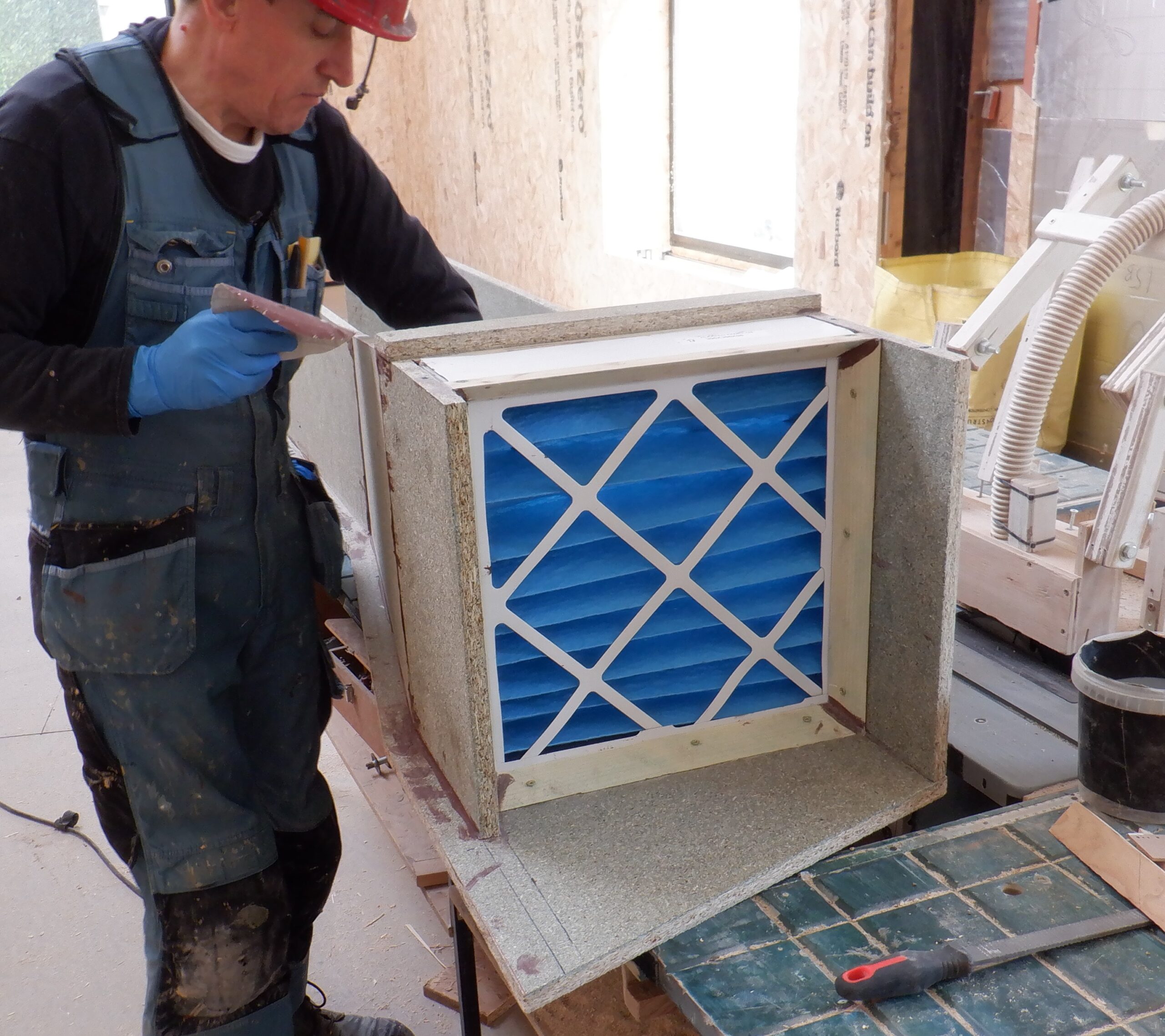
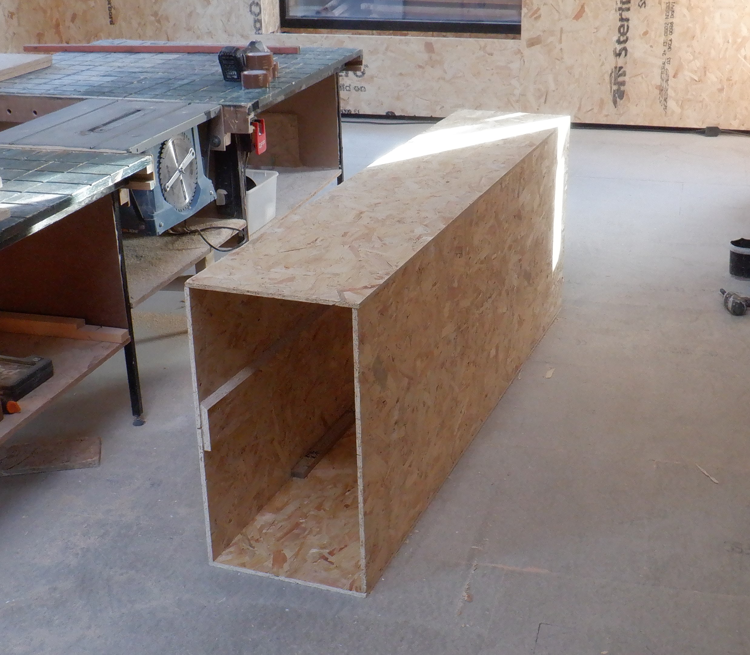
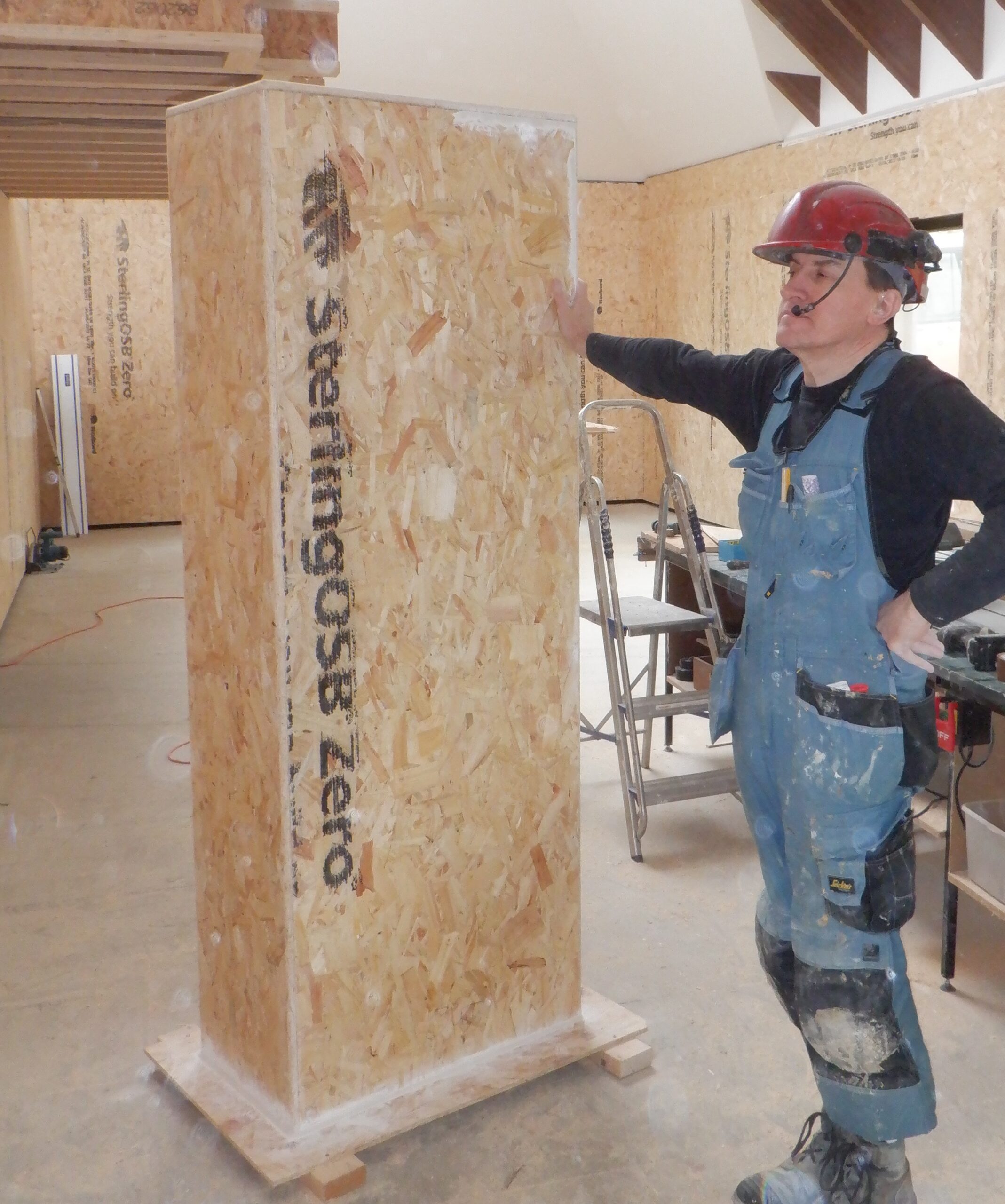
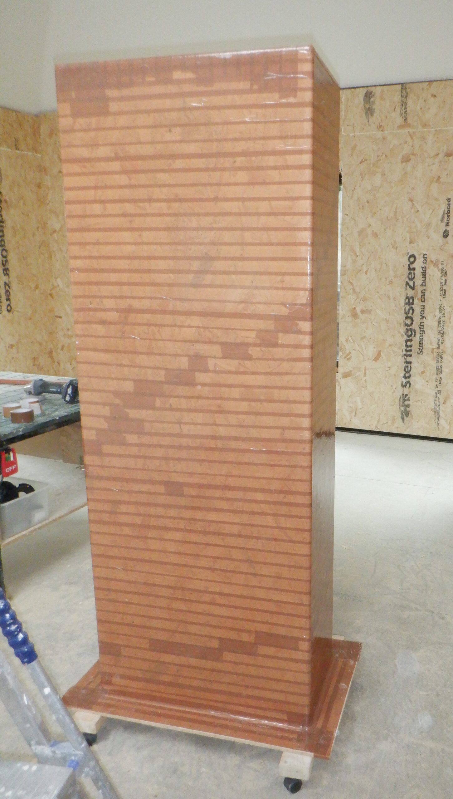
While we were waiting for that to arrive, we switched over to doing work on the Cloakroom instead. We resumed the construction of the new smaller mould, measuring 600mm by 300mm and only 1700mm tall. We decided that we would follow the same design and method of assembly, because one of us (the thin one!) still can slide inside and screw .. and unscrew .. the various fixing points around the base of the mould and up both sides as well. We screwed on a chunk of CLS piece to the bottom board and tied a rope to it so we could pull off the final piece when the tank is constructed and we were disassembling the mould.
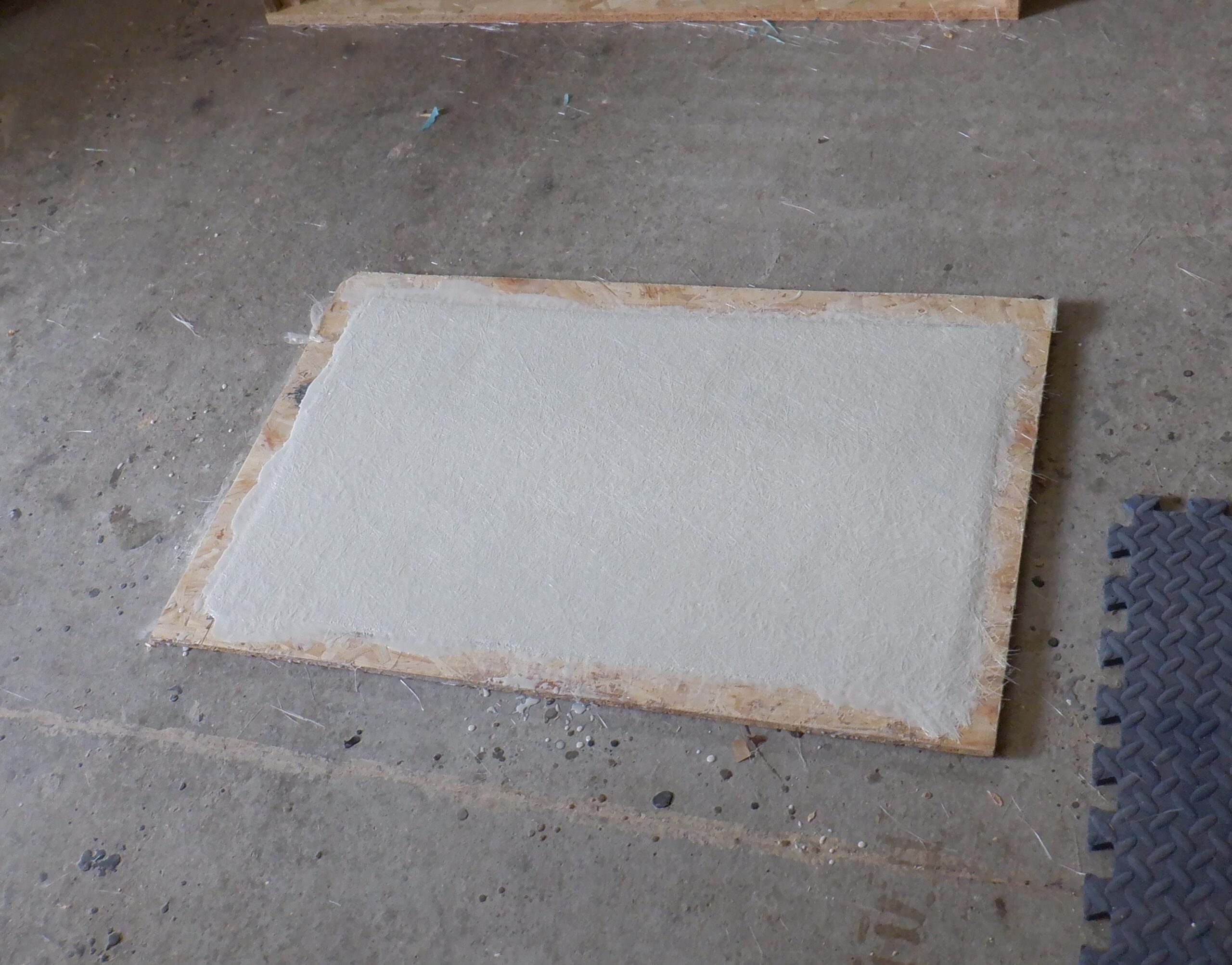
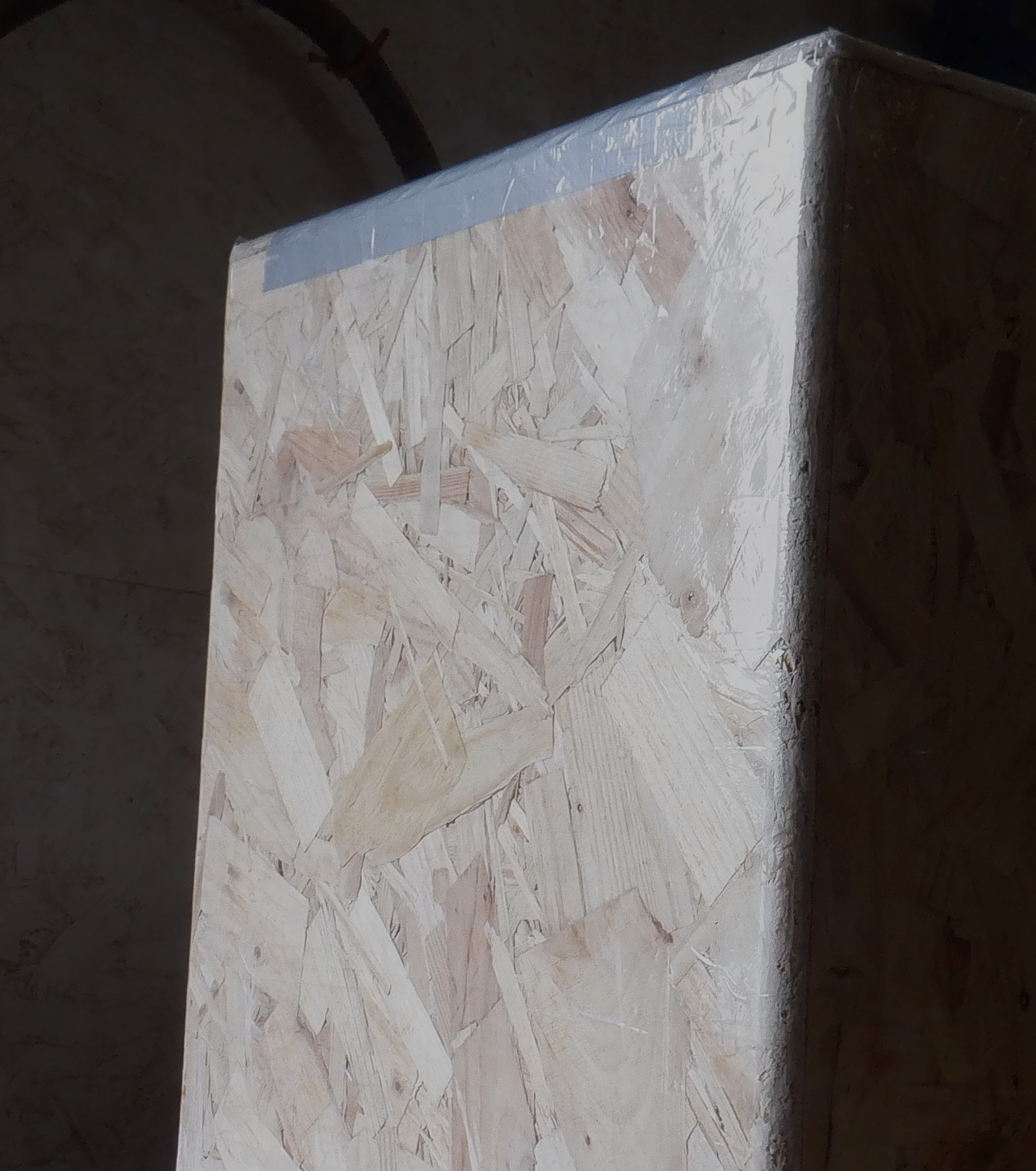
We routed all the edges to make them smooth and rounded, just like last time, to provide a gentle change of direction so the fibre glass has maximum strength going around corners. We put it on a large base and then filled the bottom edge with polyfilla to round that final edge that will form the flange of the tank.
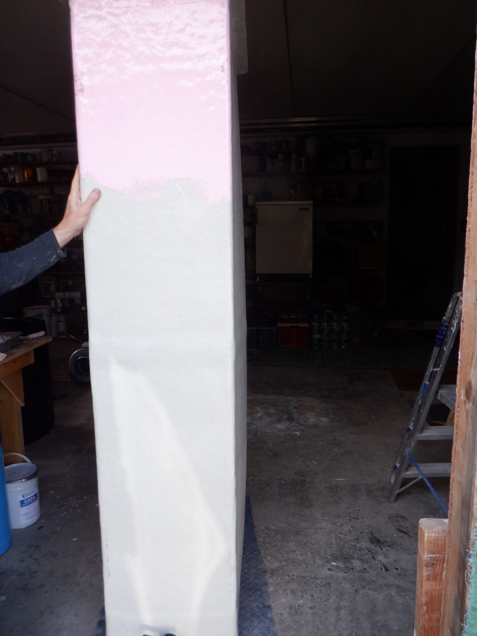
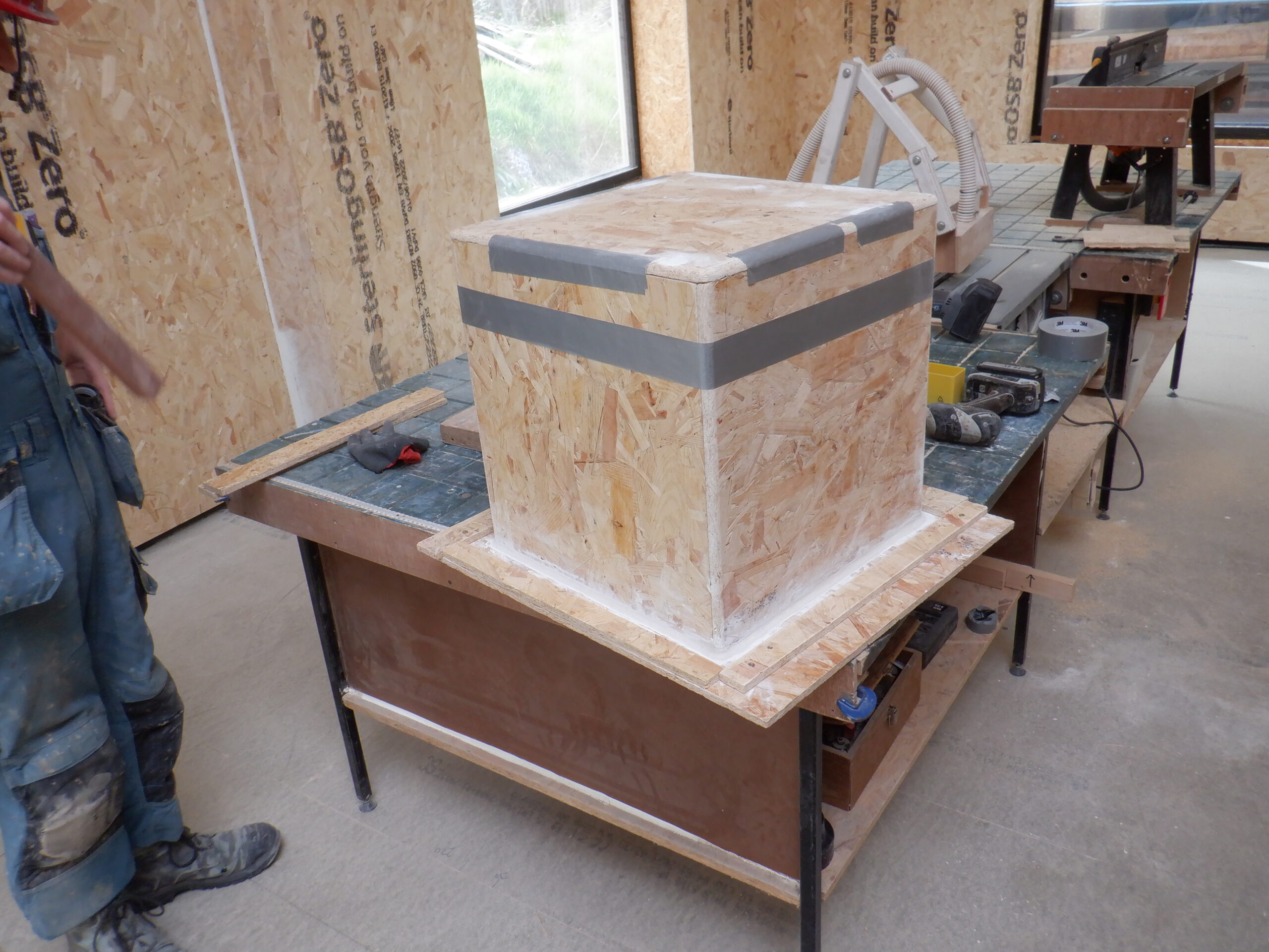
The whole thing then got wrapped up in parcel tape, to act as a mould release. We switched back to using the clear sticky tape because we discovered that the brown parcel tape was too thin and it allowed a lot of the sticky to ‘leak’ through the plastic film and deposit it on the fibre glass resin. Our test tank didn’t suffer this fate and that used this clear tape. We had one whole roll left and a little bit on another roll. We almost made it! We had to use some of the brown tape but from a different roll which we hope is of a higher grade and not cause too much trouble. Fingers crossed!
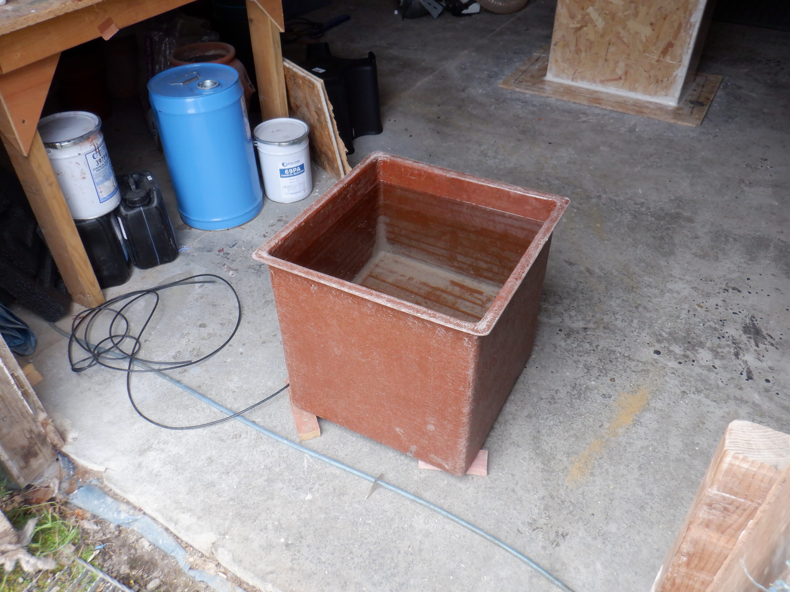
We transferred the mould back to the Garage and put it back on the same spot as the previous tank! It really makes a mess on the garage floor and we will definitely will need to come along and grind off all these splash marks etc.!
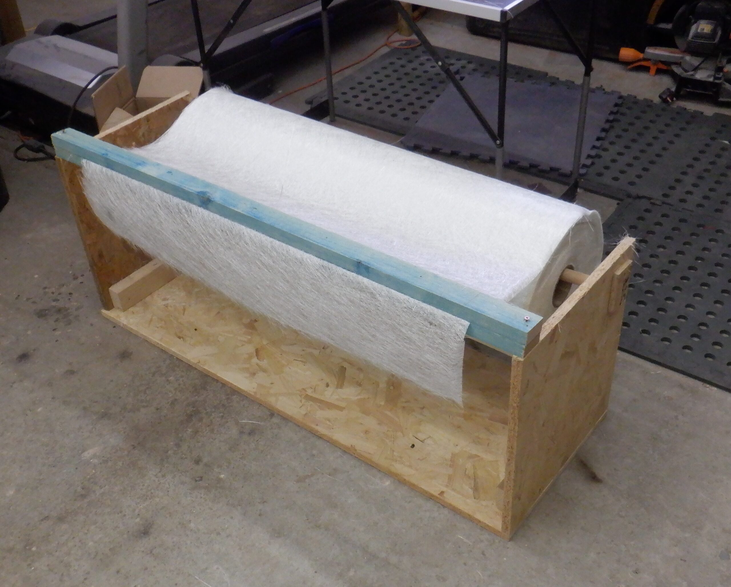
We then cut off our giant roll of glass fibre matting sixteen pieces measuring 1850mm each, for which eight of them were folded up into a pile, and the other eight was torn at 165mm from one end. The larger pieces were folded up and put into a pile too. the 165mm cut-off pieces were then torn into eight 700mm lengths and sixteen lengths of 400mm, all in their piles as well. These pieces are the base of the tank, to make eight layers of matting in total. The other longer pieces will wrap around the tank itself, hence the 1850mm number, the circumference of the tank. The final piece of preparation was to cut off our woven glass fibre cloth a piece of 450mm length and cut the width in half, making two pieces of 450mm by 775mm. These will go on the base. Then, two longer pieces of 1900mm to form two pieces of 1900mm by 1550mm which will wrap around the tank, and almost reach the bottom of the mould (the height is 1700mm) but the flange will provide enough structural strength by itself. These woven cloth pieces are very good internal structural elements because they are made using a single fibre of glass filament and therefore, will provide more tensile strength, at the 90°C temperatures that this tank is going to have.
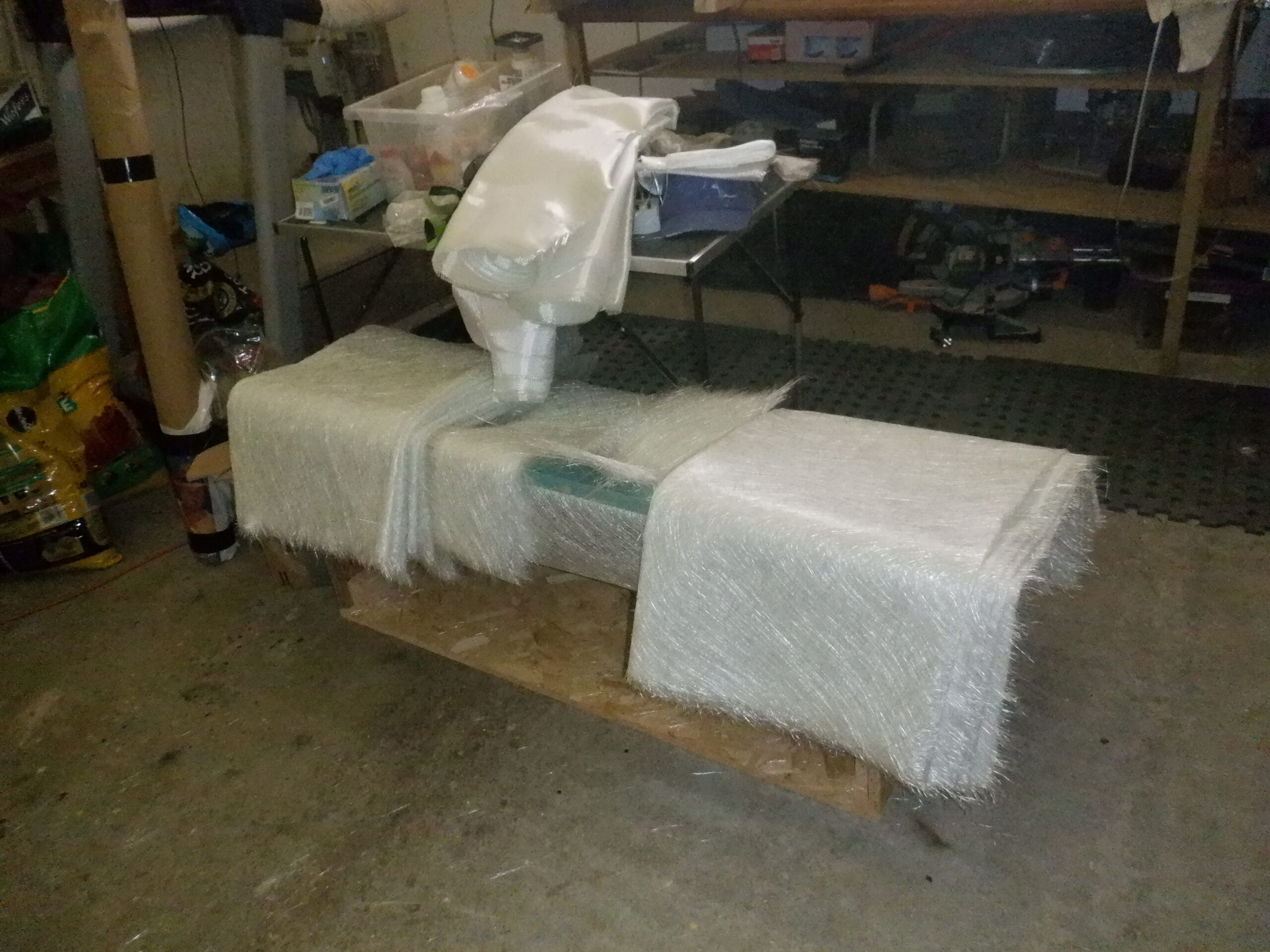
Materials staged for hot tank
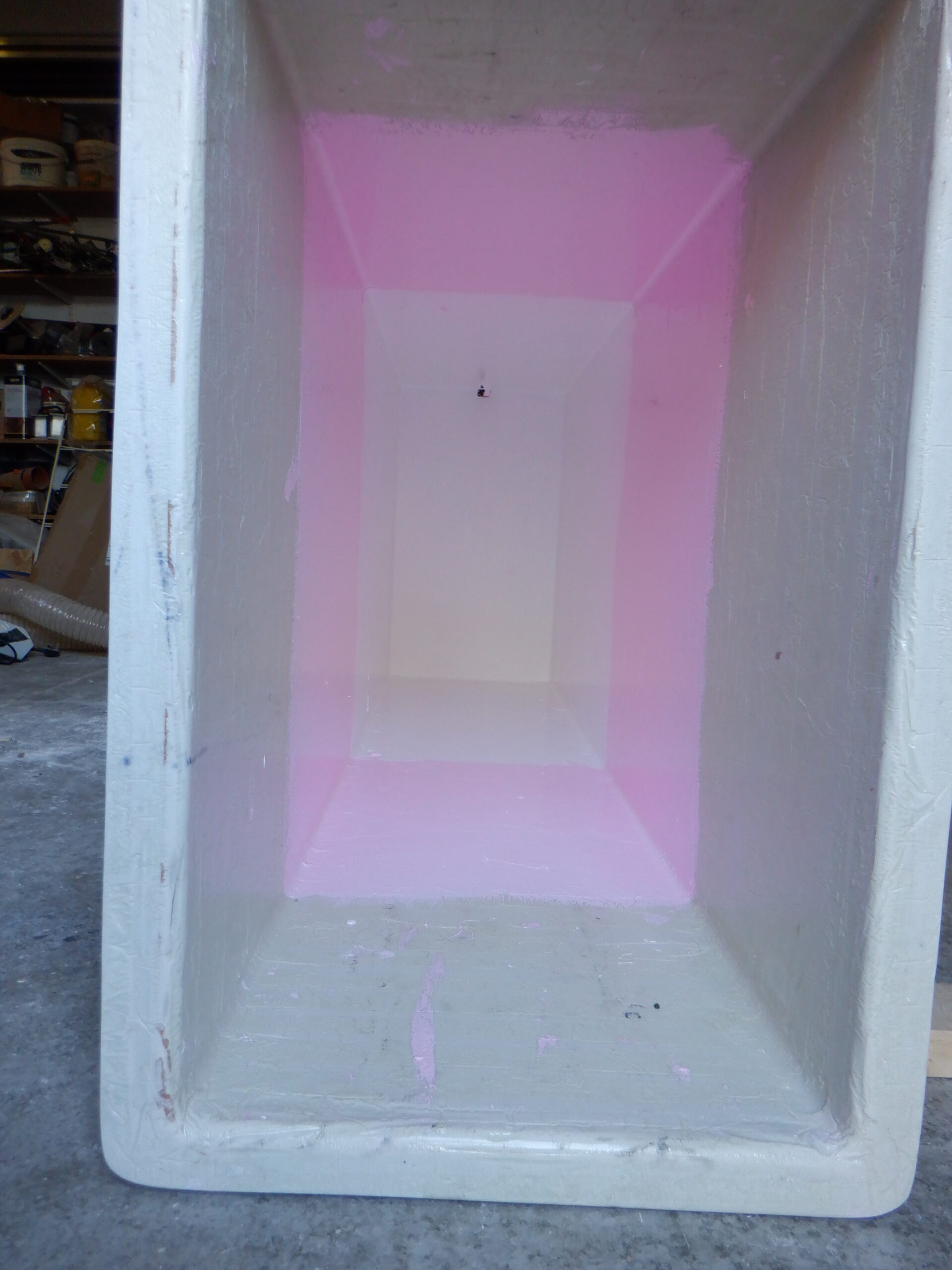
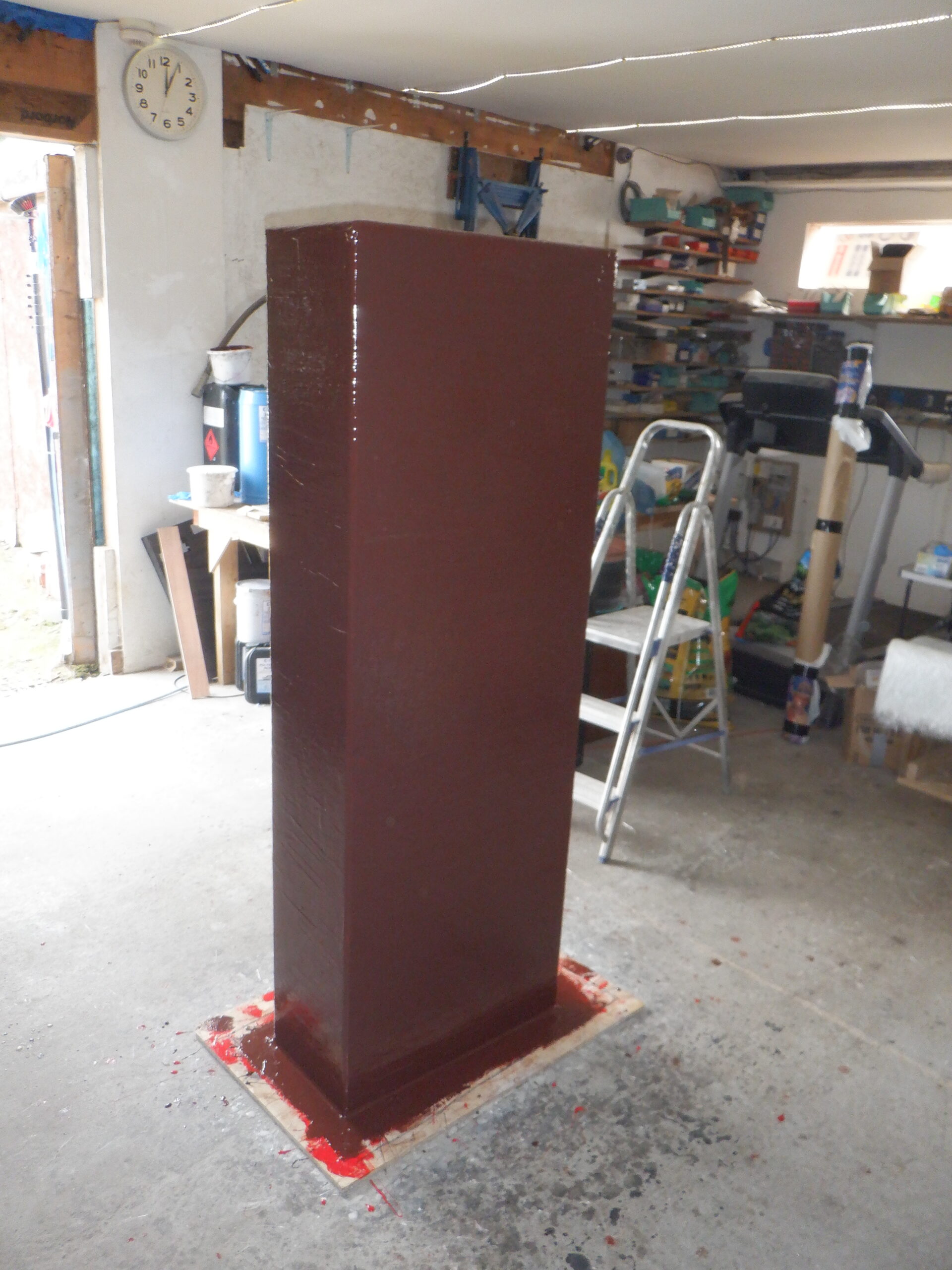
We started really early the next day at just after 8am because we needed to put on two layers of what is called ‘Gel Coat’ which are extra thick resin which provides a solid layer of resin without any glass fibre in it at all. The problem is that we have to wait for this Gel Coat to solidify which can take an hour, before we can put on the second layer. Hence why we started so early!! We mixed in a lot of red pigment into our 5kg tin of special resin so we can see how well it gets painted on .. or not. The first layer went on directly onto the prepared mould and left to cure.
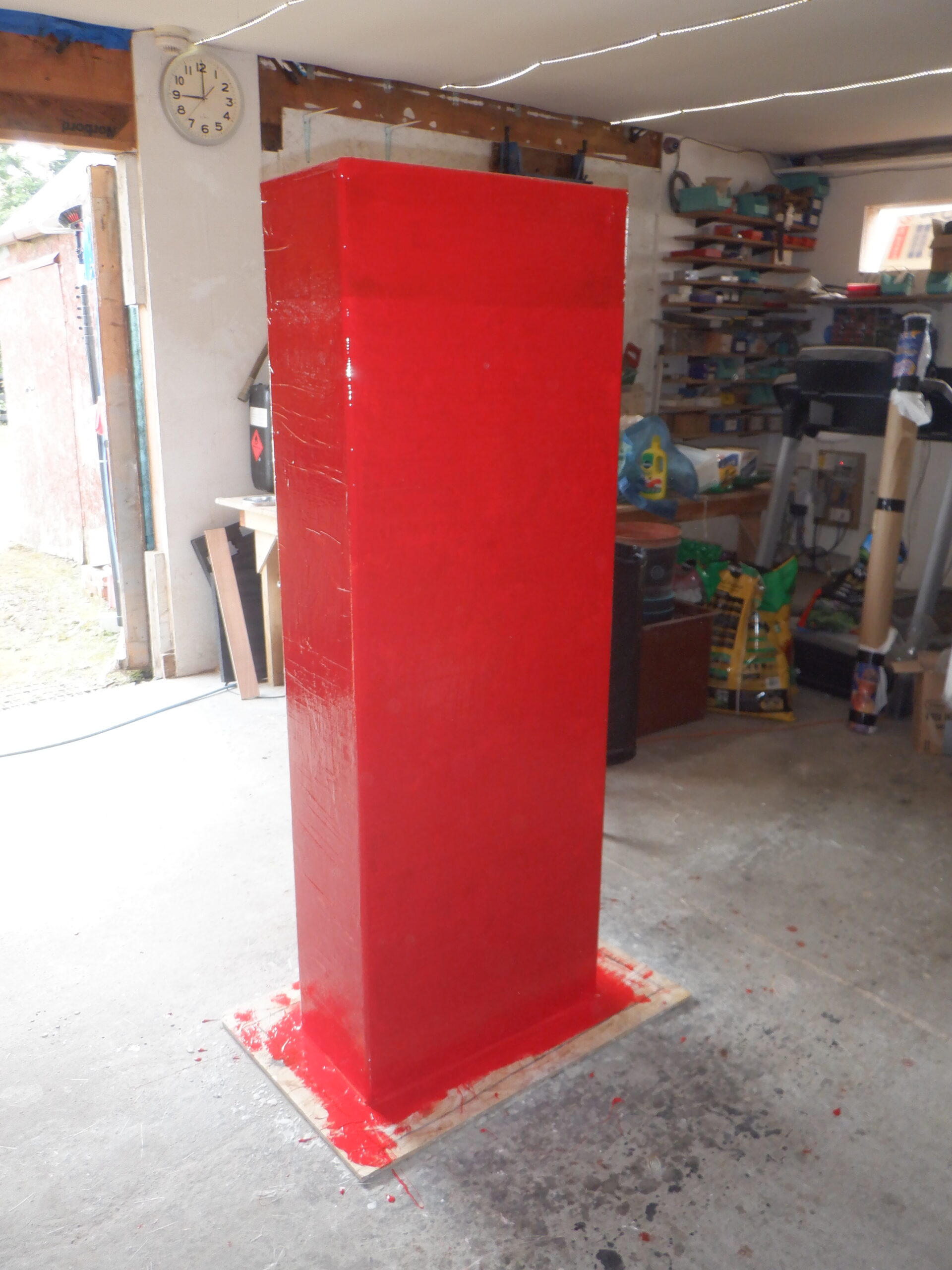
First Gel coat applied (1)
First Gel coat applied (2)
we then went off to have breakfast and do some of our morning chores while we waited.
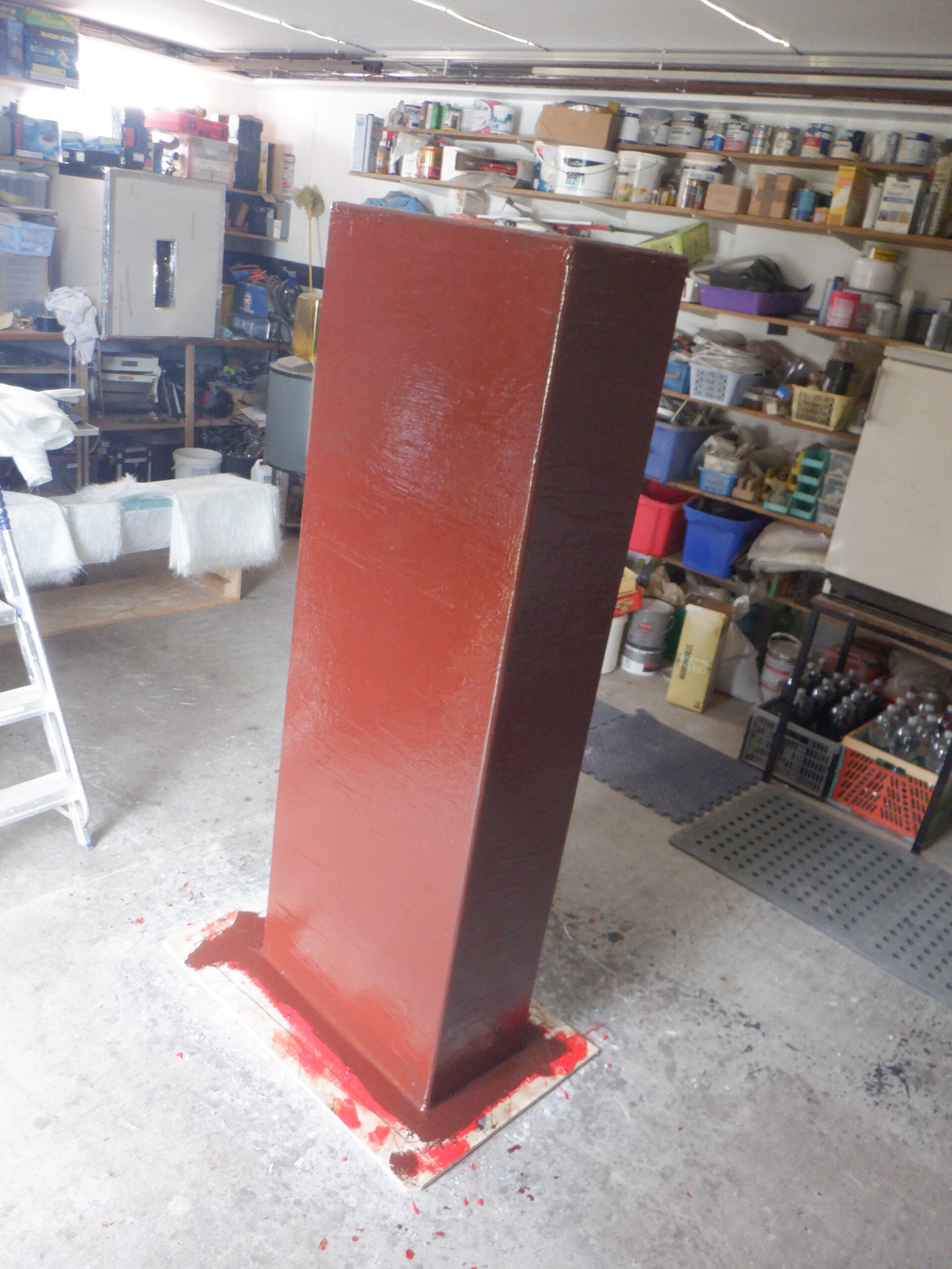
About one and an half hours later, it was firm enough to allow us to put on the second layer. We mixed in a little bit of cyan colouring dye and it turned to a muddy brown colour !!
That is fine as we can see a contrasting colour so we can see where we painted etc.
Second gel coat (1)
Second gel coat (2)
This brought us up to approximately 12noon so we decided to have an early lunch and resume work at 1pm, instead of our usual 2pm.
The next stage is putting on the glass fibre matting and coating it with regular resin this time. We first coated the whole mould with naked resin to wet the surface and helps hold the matting material on. We started at the top of the mould and put on two narrow strips and rolled more resin on top. Then, wrapped horizontally our wide matting strip and wetted that down, followed by the second horizontal but slightly narrower strip, to the bottom half of the mould and down onto the flange as well. Then, we proceeded to do this again, alternating with the horizontally strips so that the join is always well covered. We did the same at the top of mould too, alternating between two narrow long strips and four shorter ones but rotated 90degrees, so, again, the overlapping joints are thoroughly covered and reinforced every time.
We did three layers of matting before we put on one of the two woven cloth layers. We then put on a fourth matting layer on top of that, before we stopped for the day. We were getting tired.
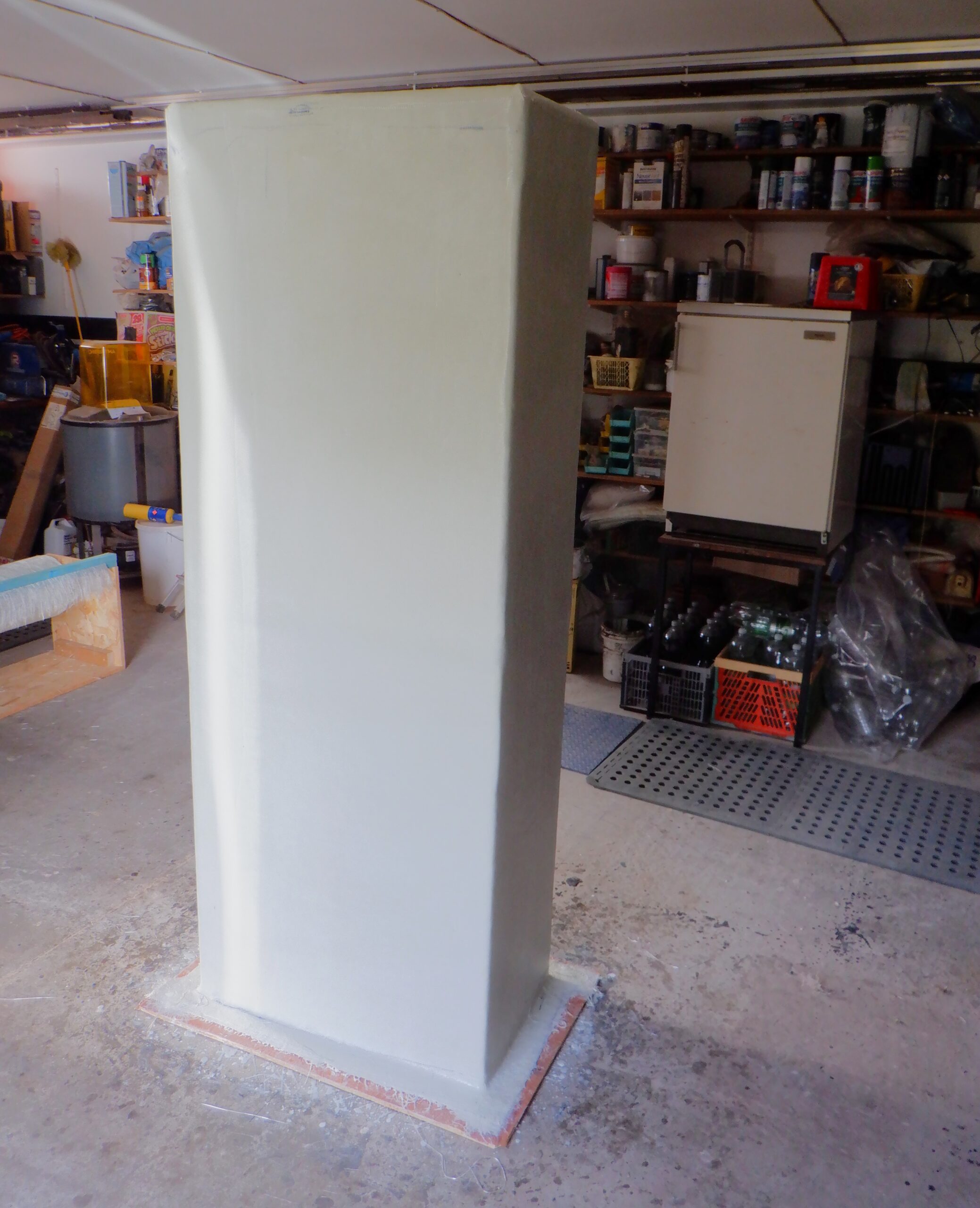
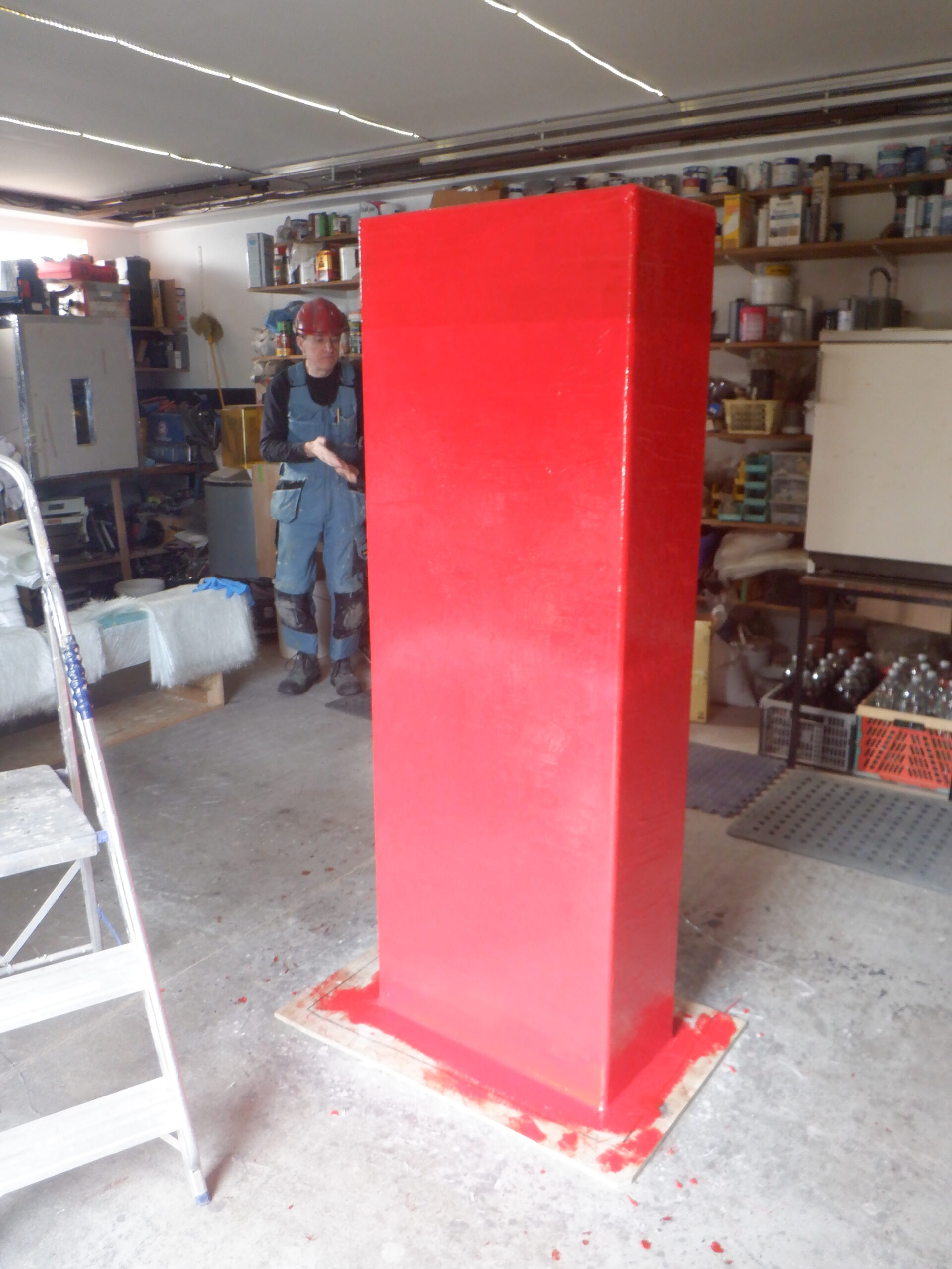
So on the next morning, again slightly earlier than normal, at 9am instead of 10am, we resumed our work of building up layers of glass fibres. We put on two more layers of matting (which are random short pieces of glass fibres) before we put on our second woven cloth. And then we finished off putting on the final two matting layers. We rolled the surfaces all over using an metal aluminium textured roller which is designed to colligate the various layers of glass fibre and the resin together and also make sure that any trapped air bubbles are forced out of the mixture as well. We have been doing this several times over during the whole job.
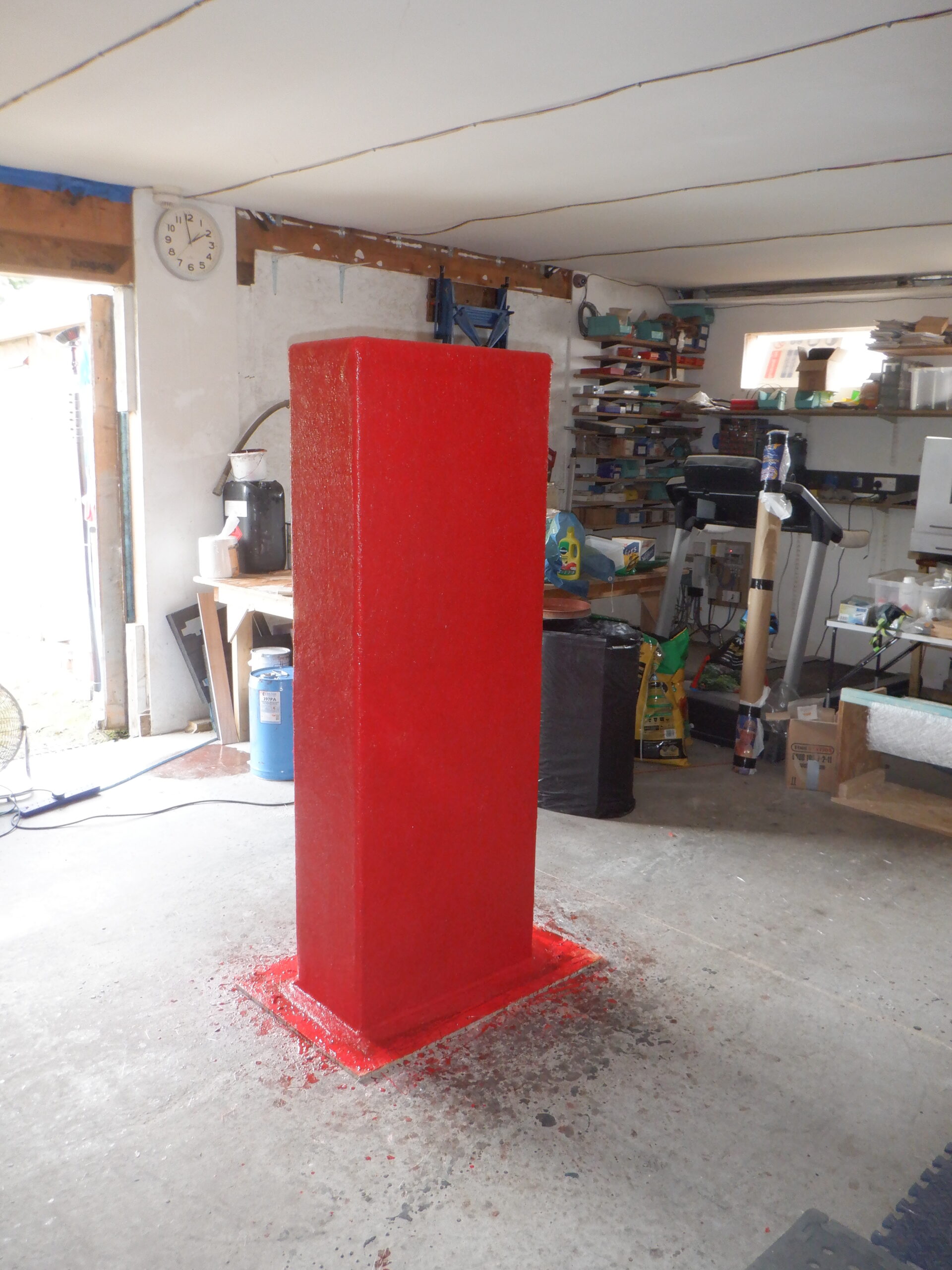
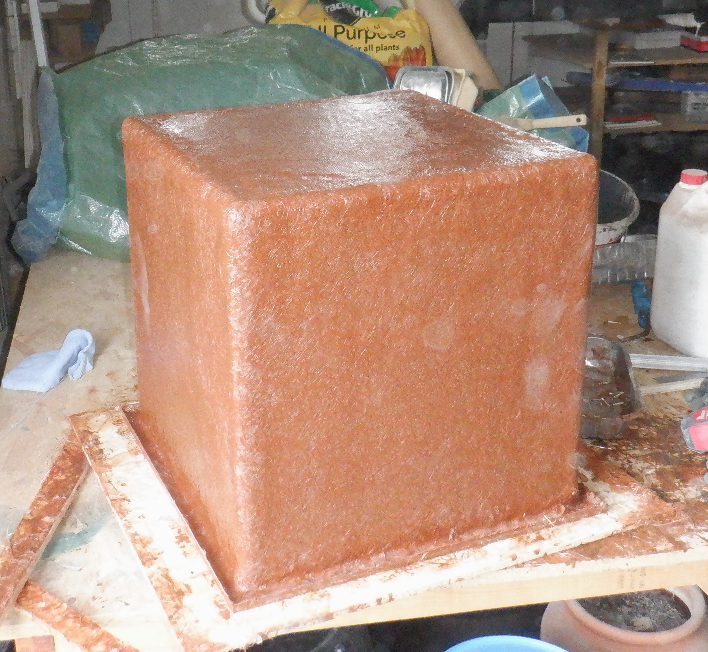
All layers applied (1)
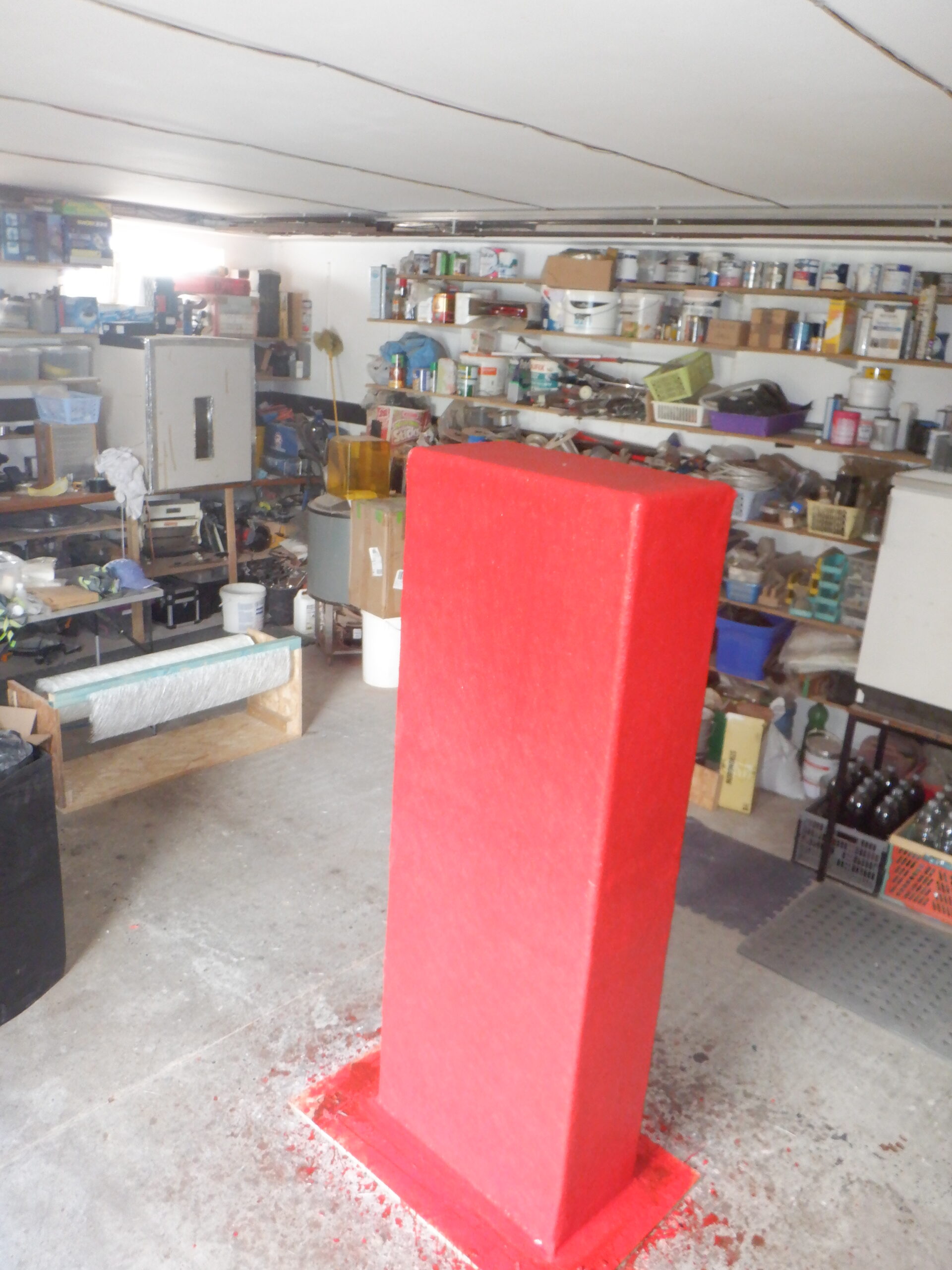
All layers applied (2)
We left it in the middle of our Garage for a few days, to cure and harden, before the next job of removing the mould.
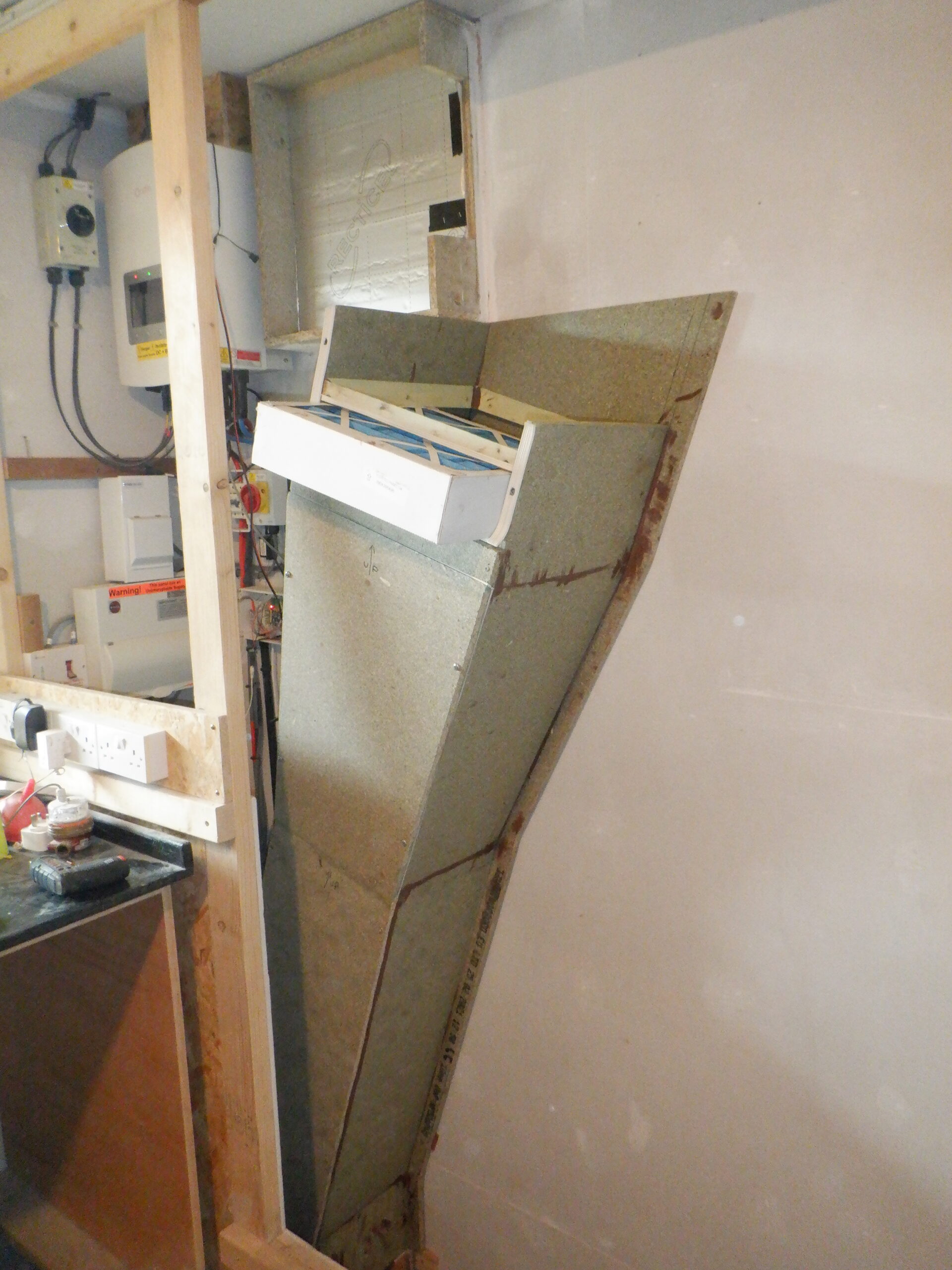
After a couple of days of curing and hardening, we tackled the job of removing the wooden mould. The first job was to trim the flange all the way around, using our wiggle saw and a piece of 25mm thick piece of wood as a guide. This will provide a flat surface for our lid to sit on when we have finished installing the various elements that will be dangling inside the tank.
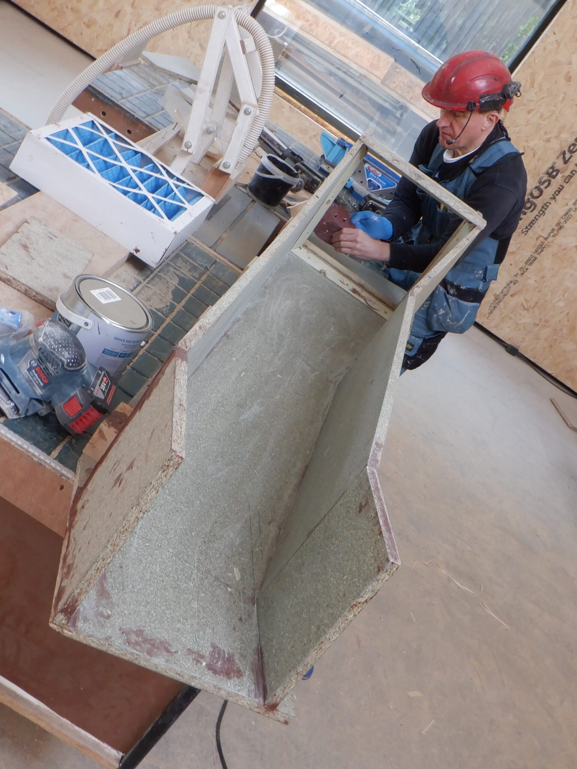
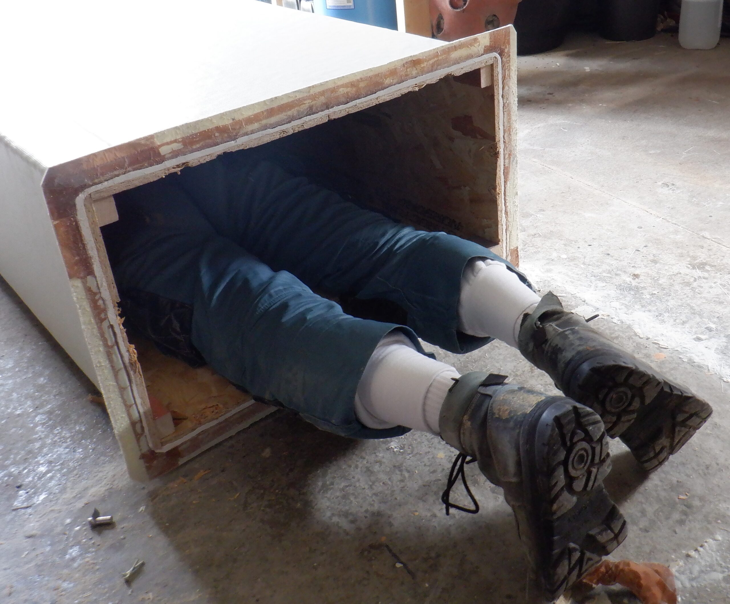
The next step in removing the mould, is to unscrew the base off, which then gives us access to all the screws that holds the four long pieces in place. we had to crawl inside with the screw driver, to reach those screws!!
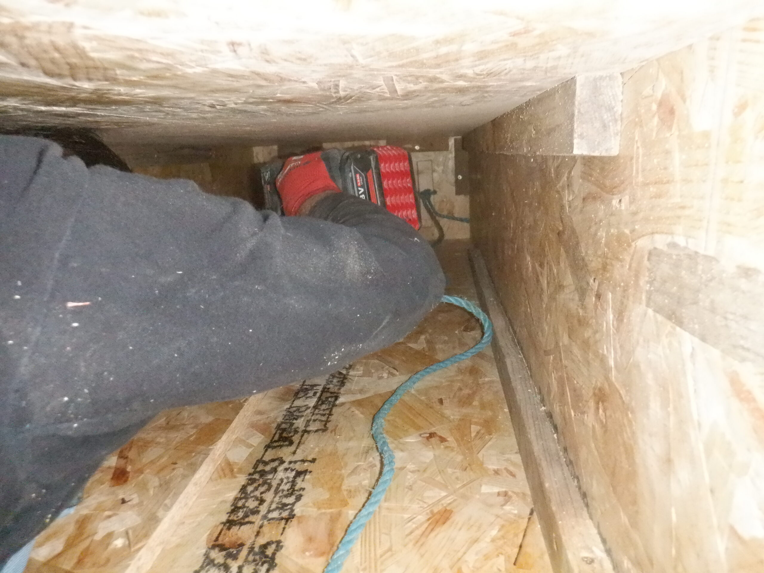
Undoing mould fasteners
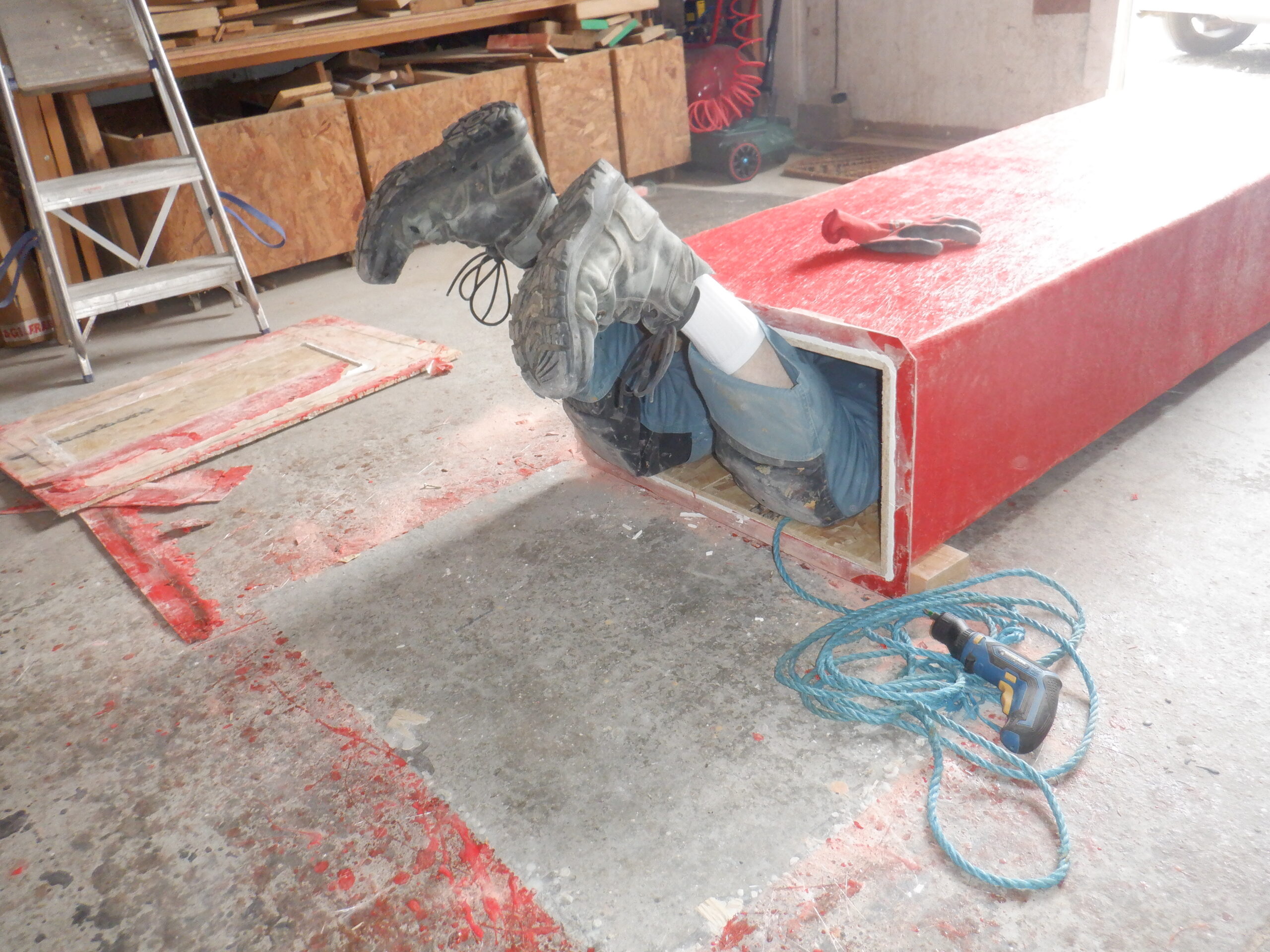
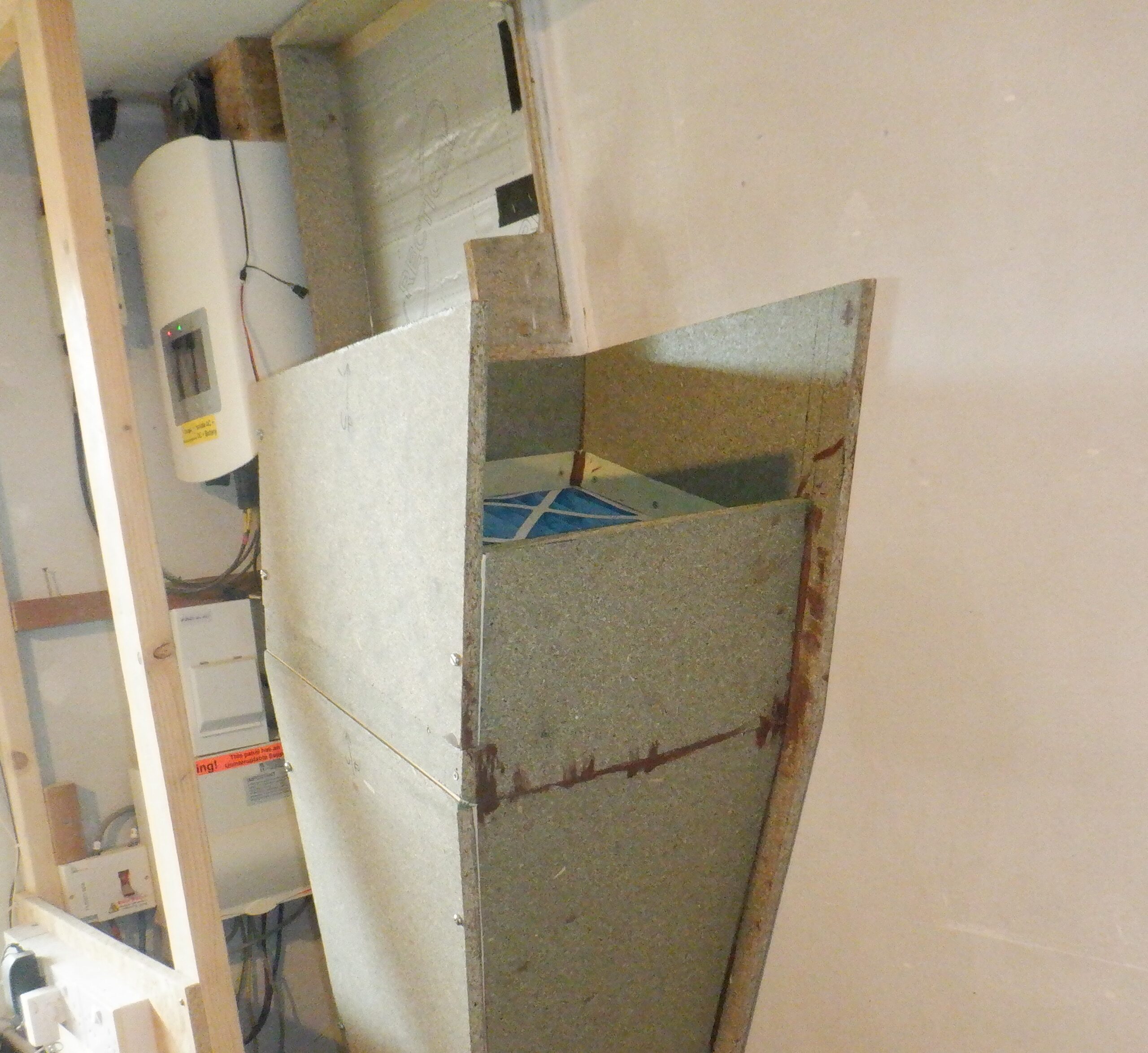
All the way in…
Then, we could lever off each side in turn, taking out the wider ones first, and then the two narrow ones last. This left the bottom piece, the base. It is an 18mm thick OSB board and we tried .. and tried .. and tried .. to tug on the rope to yank this final piece out. But, it refused to move!
In our wisdom, we thought that we had given the bottom piece enough freedom to rotate out when it was pulled via the rope, but it seems to be well and truly stuck.
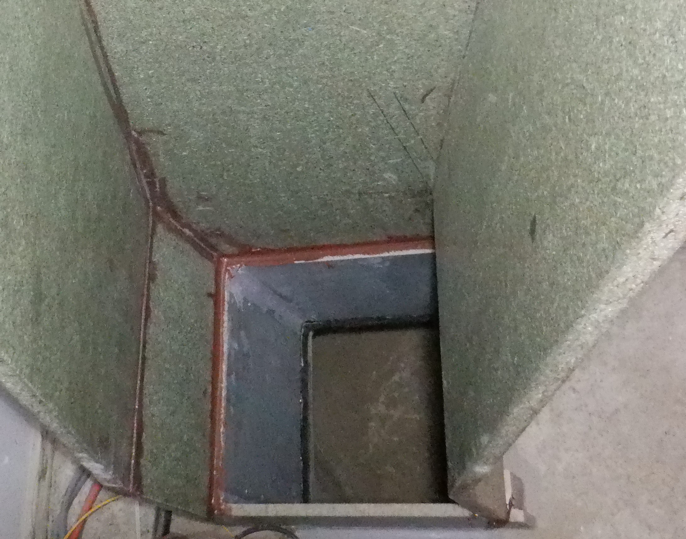
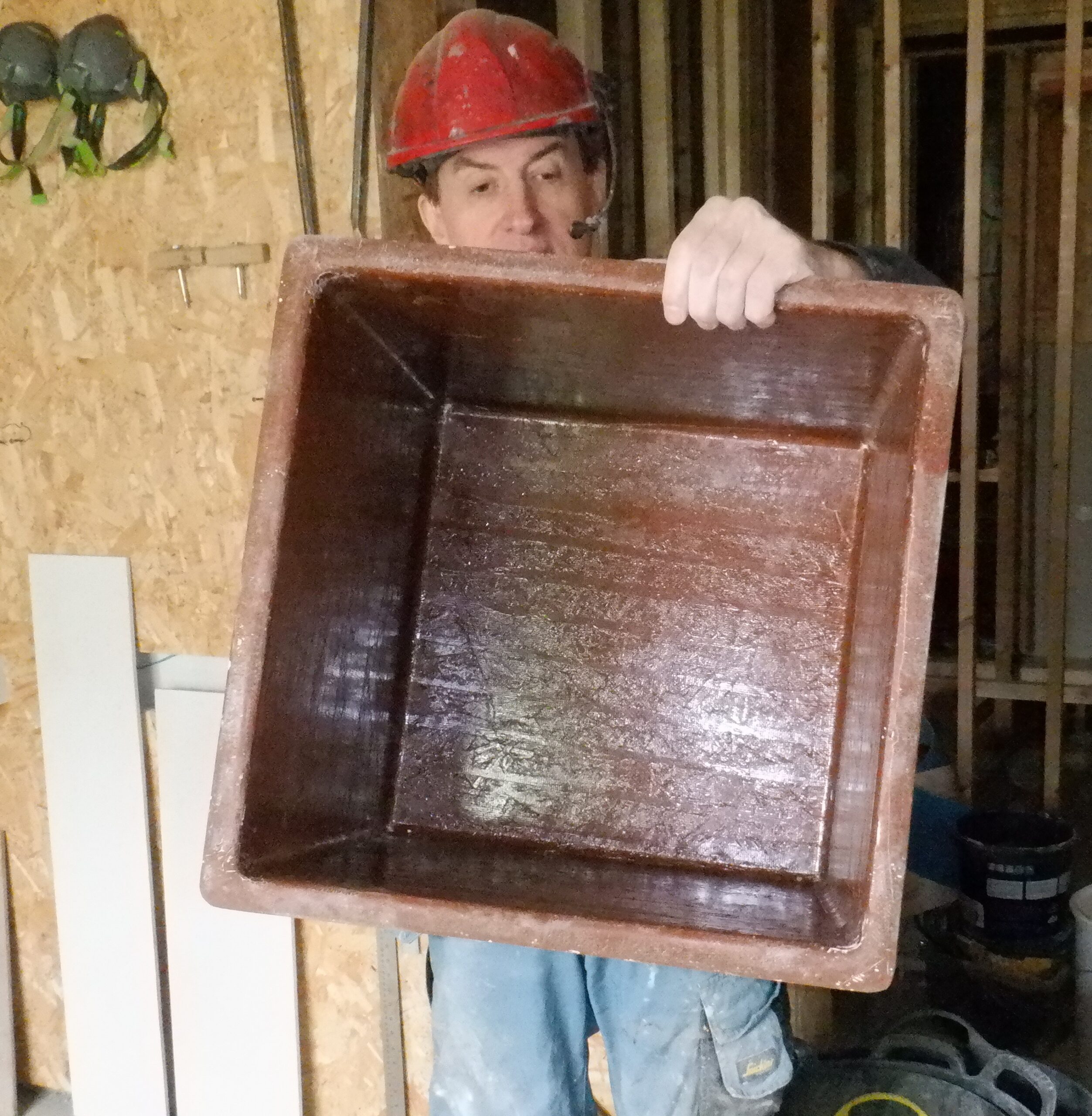
This means that we had to crawl up inside and use various machine tools to the board .. but it was very nervous because we didn’t want to damage the fibre glass and its waterproof coating. So, we slowly hacked our way through the layers of the OSB board, pulling off small strands and eventually, we manage to reach through and get a crowbar in to lever one larger piece off, which then allowed the crowbar to reach in and lever the second half off!! O Boy !
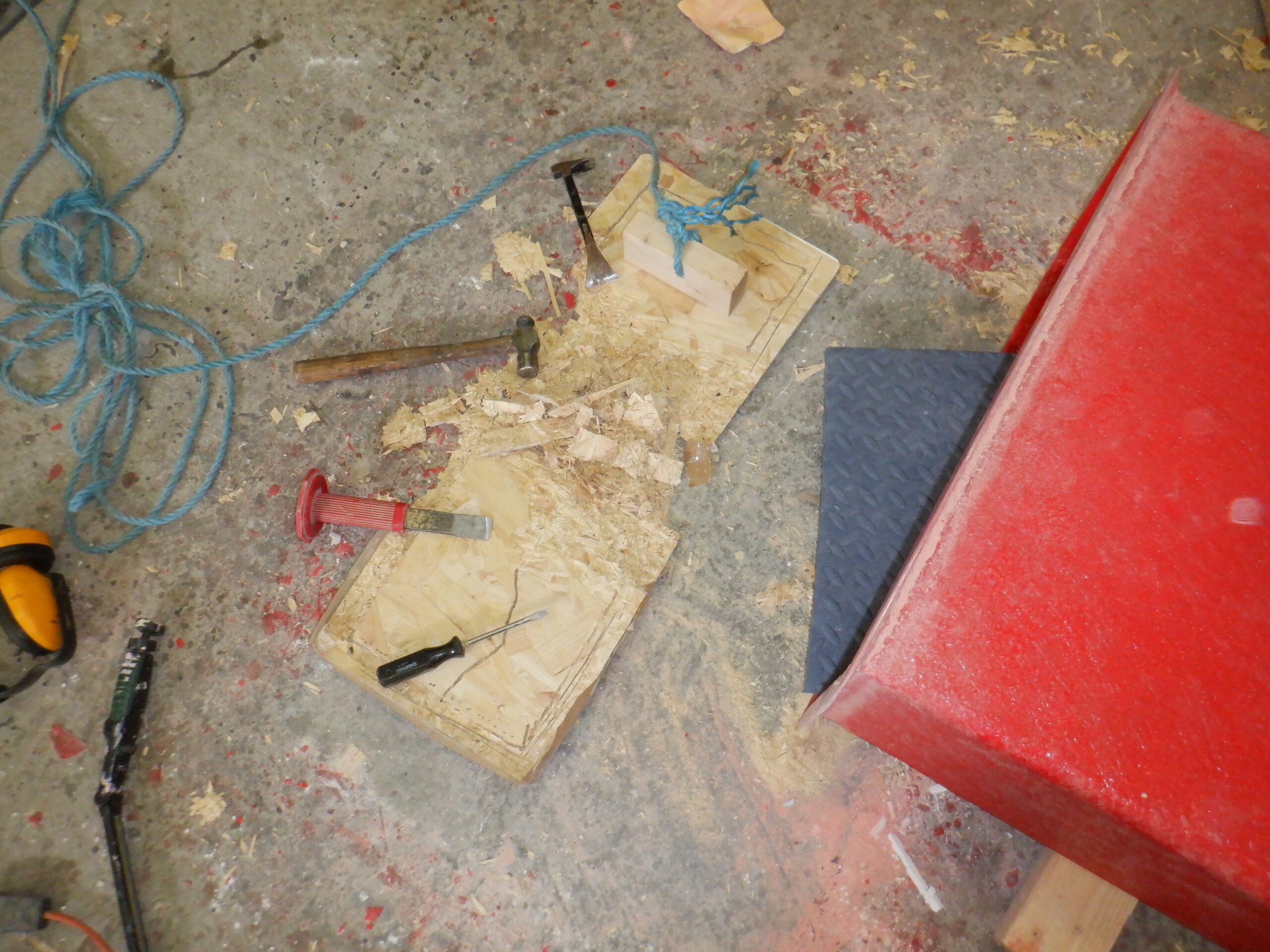
The destroyed Top of Mould
But .. ..
We had after all scratched in several places, and gouged one spot deeply, plus also one of the corners seems to have lost a piece when this stubborn board finally popped out.
This means that we have to do some repair work so we cleaned everything, sanded the surfaces to roughen it up for the new coat of resin, blasted it with our compressed air and then give it a thorough wipe with Acetone to also help ?key? the surface, ready for the resin. We mixed 65mg of our red resin, dropped some cyan into it, to turn it brown so we could see where we had painted it and then mixed in 2ml of hardener to make it set in a quicker time, but also, to make sure that this resin will cure thoroughly and not leave a sticky surface at all.
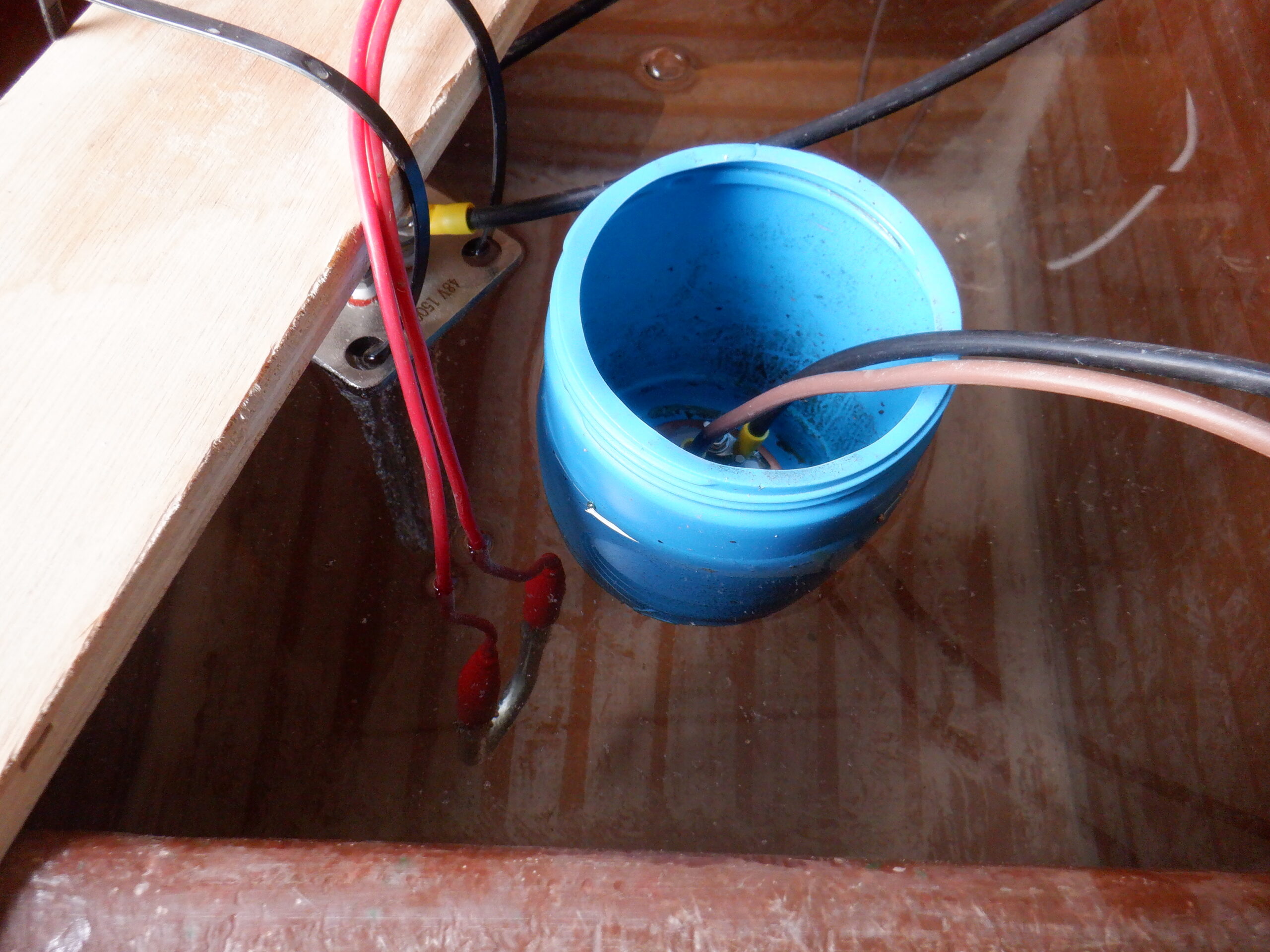
We then crawled in with a light strip, and dabbed the affected areas.
Damage repaired
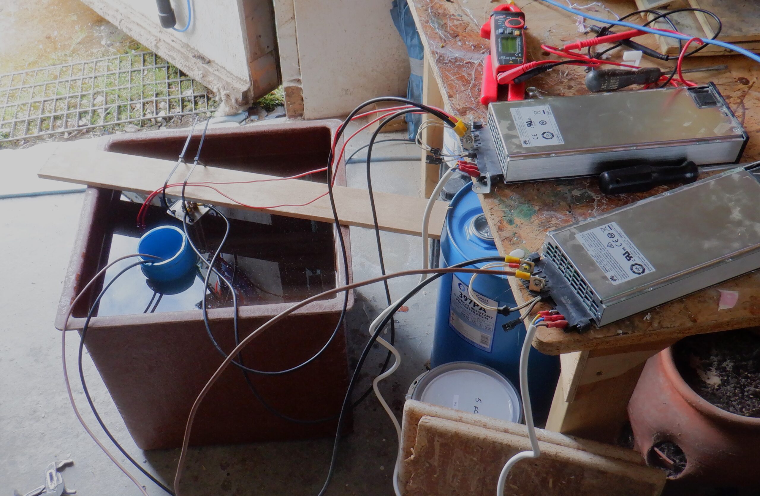
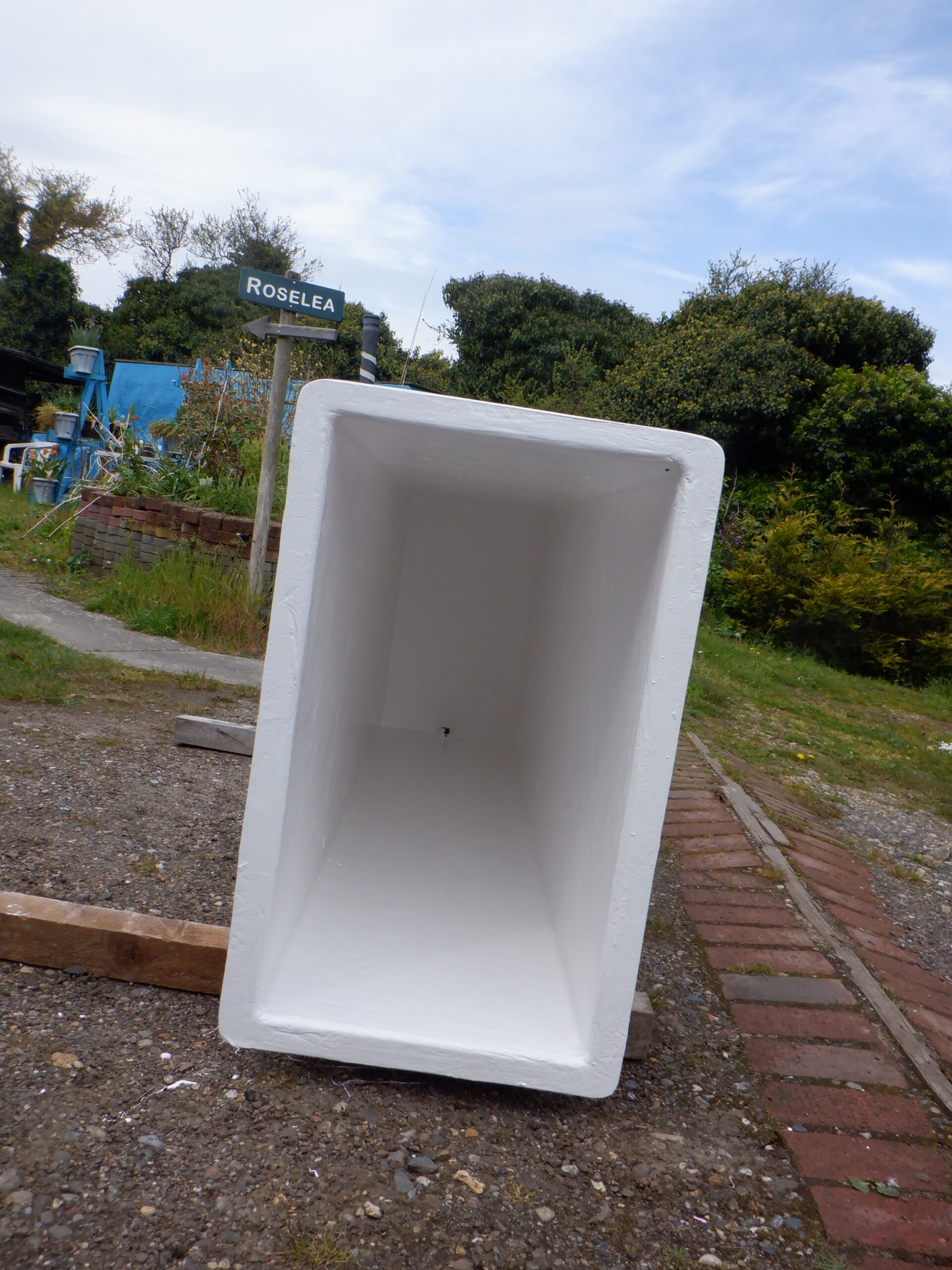
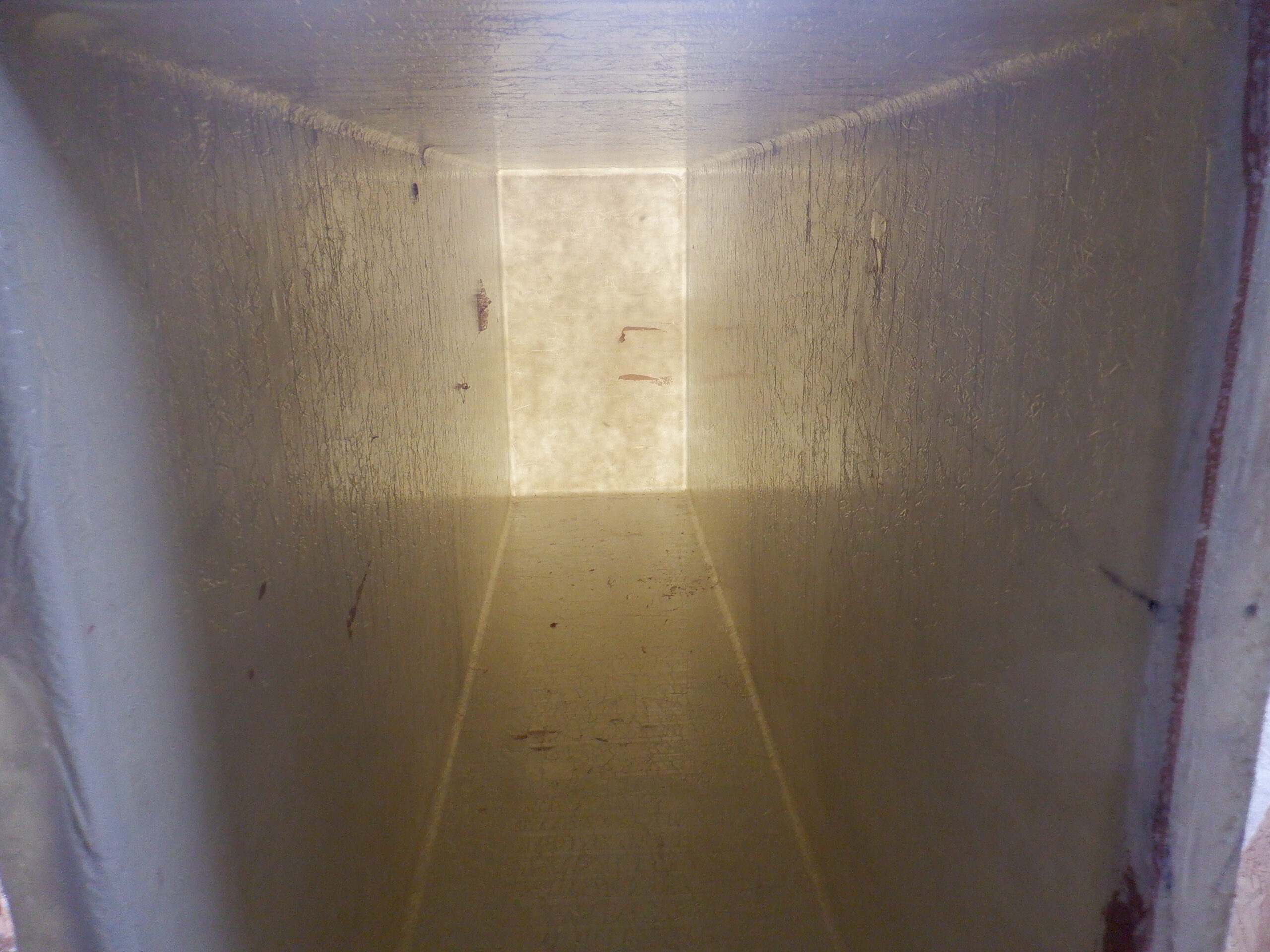
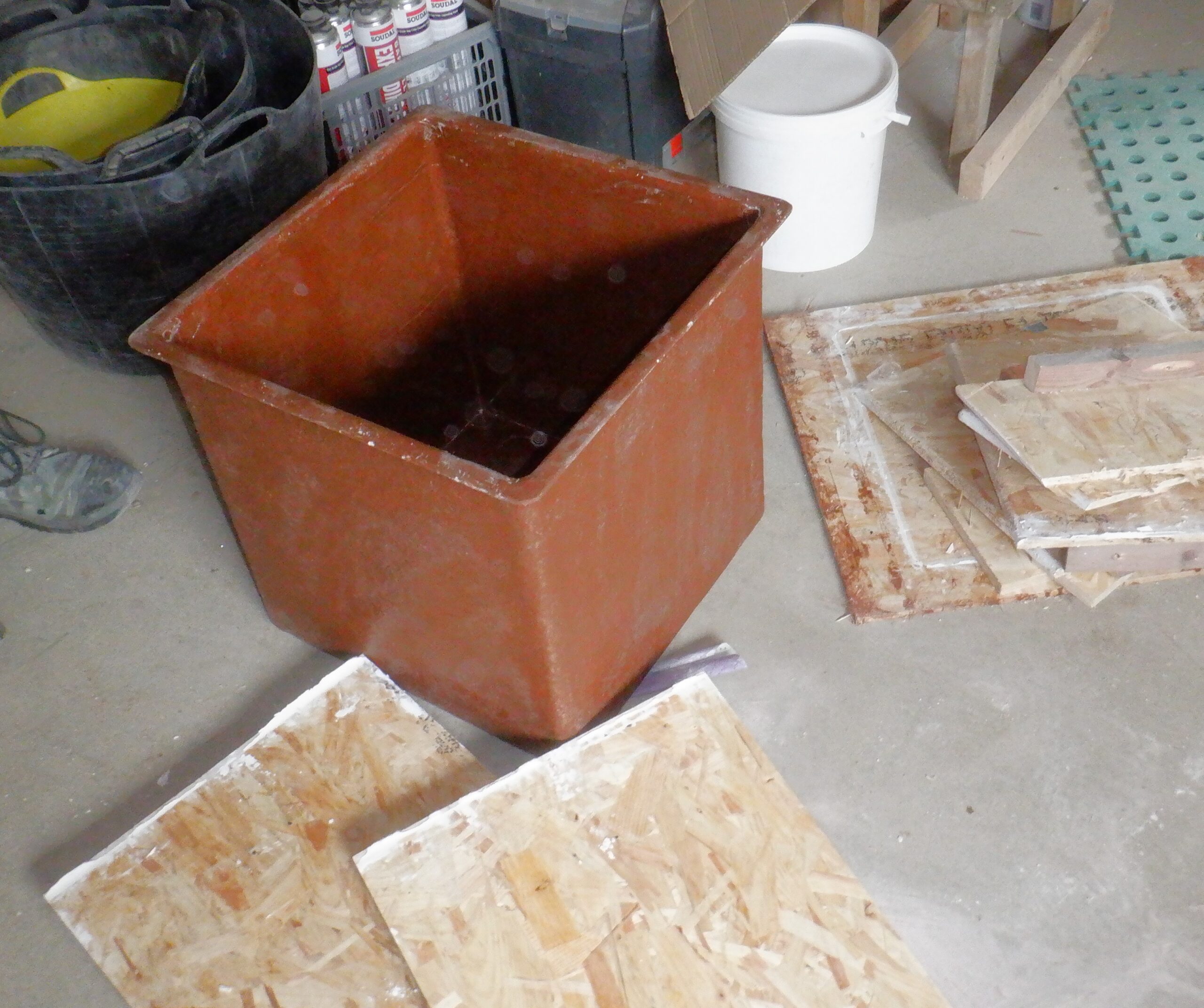
Now it is time to test it. We left it alone for the weekend and then poured in water to find out if we had got any leaks!!
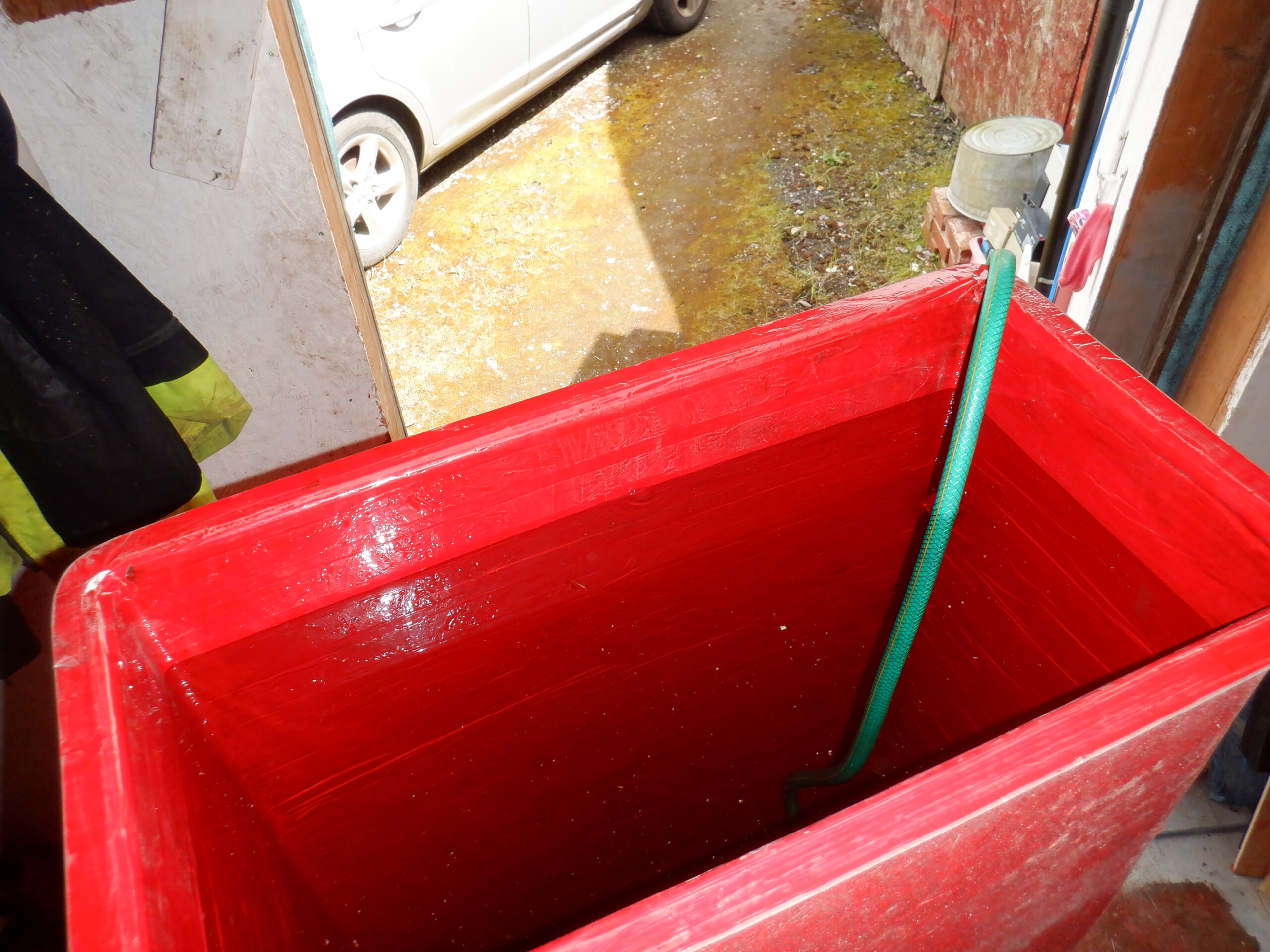
Testing the hot Tank
But alas !!!!
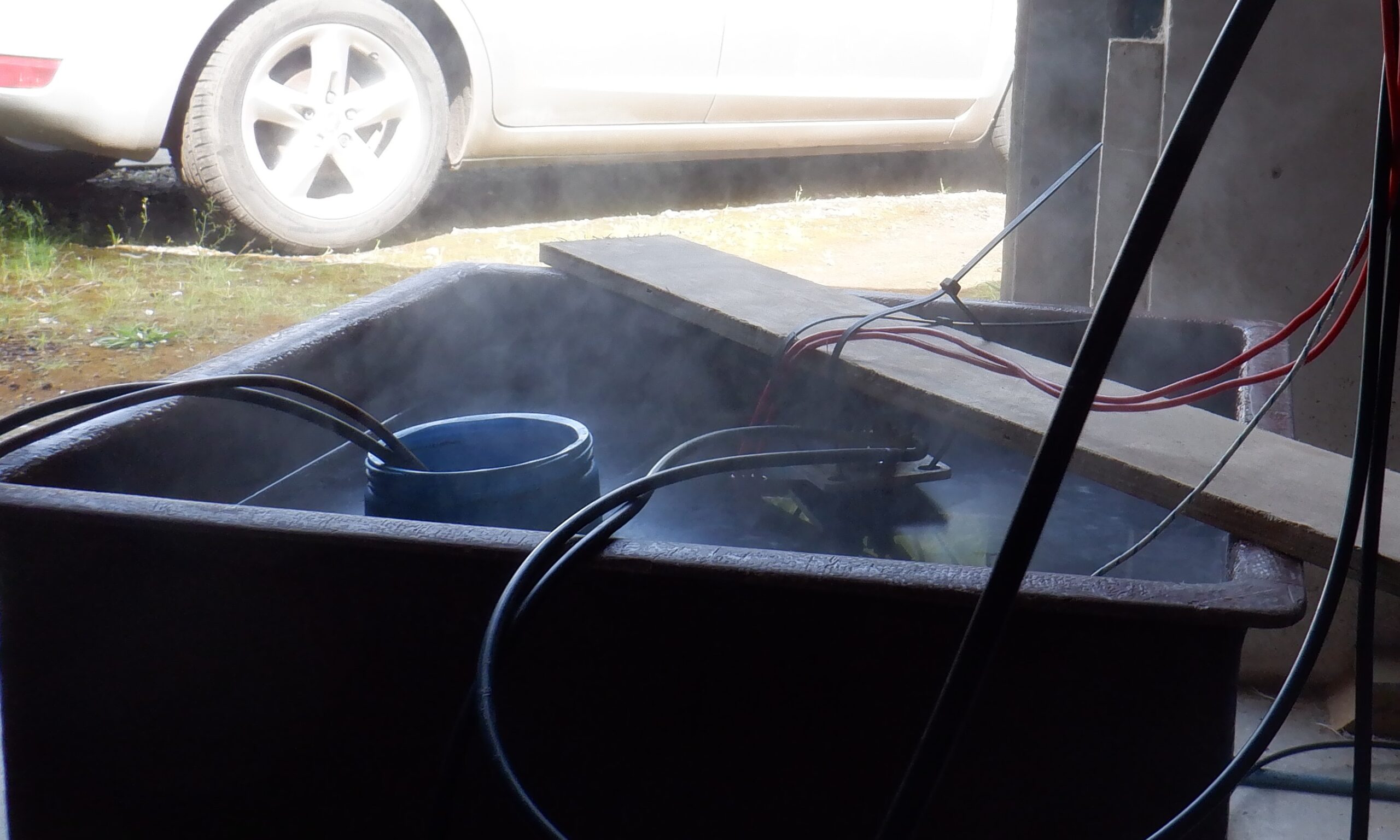
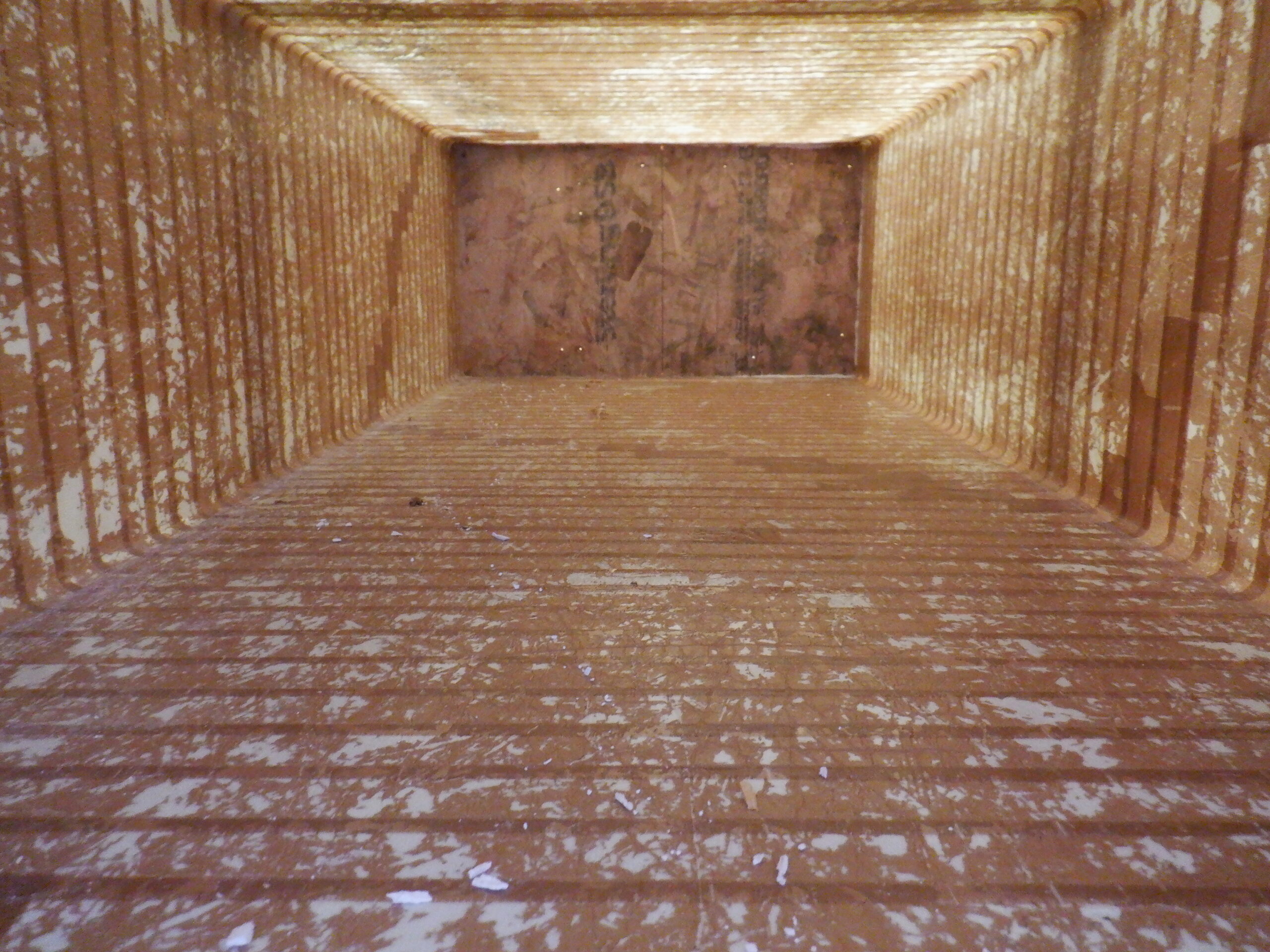
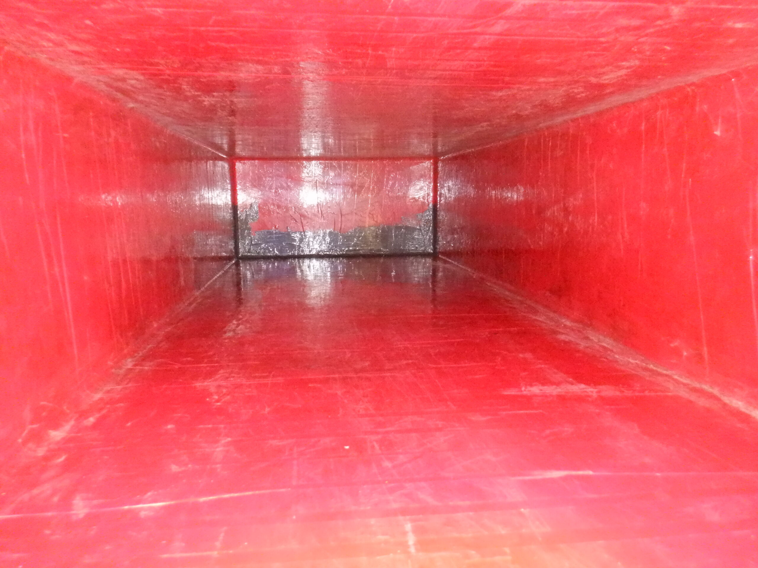
We still had a single leak, near the top, about 300mm down. How frustrating that is !! Because, it is a learning process each time we step forward with the next version, but, the trouble is, this hot water tank, is our final version and we are not planning to make any more!! We have analysed the surface inside the tank and we got lots of horizontal grooves of varying lengths all over the place and we realised that these grooves were caused by the sticky tape we wrapped around the mould and it buckled up occasionally, especially when we were going around the corner from one face of the mould to the next one. in hindsight (how awful is that?!), we should have cut off these buckled up tape and stuck on a short piece over the top to make it all smooth again. As we say, it is no good knowing that NOW .. we are not making any more tanks !!
Phew!
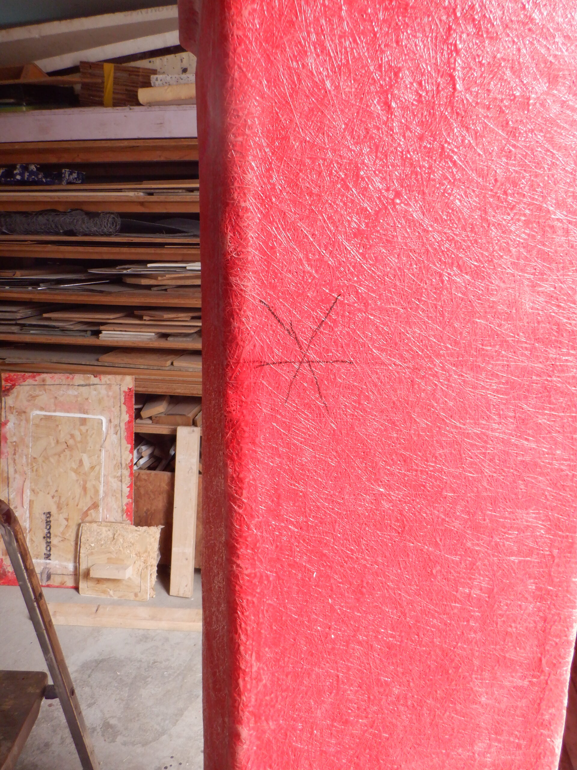
Oh Dear! We have a leak
As you can see, we are going to have to crawl inside and carefully paint each of these grooves whenever we find one. It will be difficult but just about possible. O Boy!!