When we had a spare moment or two, between doing other tasks, we explored the Cold Water System and looking at building it. We did an order for plumbing bits and pieces a couple of weeks ago, getting a collection of parts to allow us to convert our main 32mm water pipe coming down from the Header Tank and joining it to our mains powered pump, and then back out to our domestic water supply that is going around the house to bathrooms and shower rooms etc.
All the equipment is going inside our sound dampening Utility cupboard and it will be installed near the Air Ducting that is coming up out of the floor. We want to try and arrange the bits and pieces to minimised space because we have two more water pumps to be installed in our Utility Cupboard!!
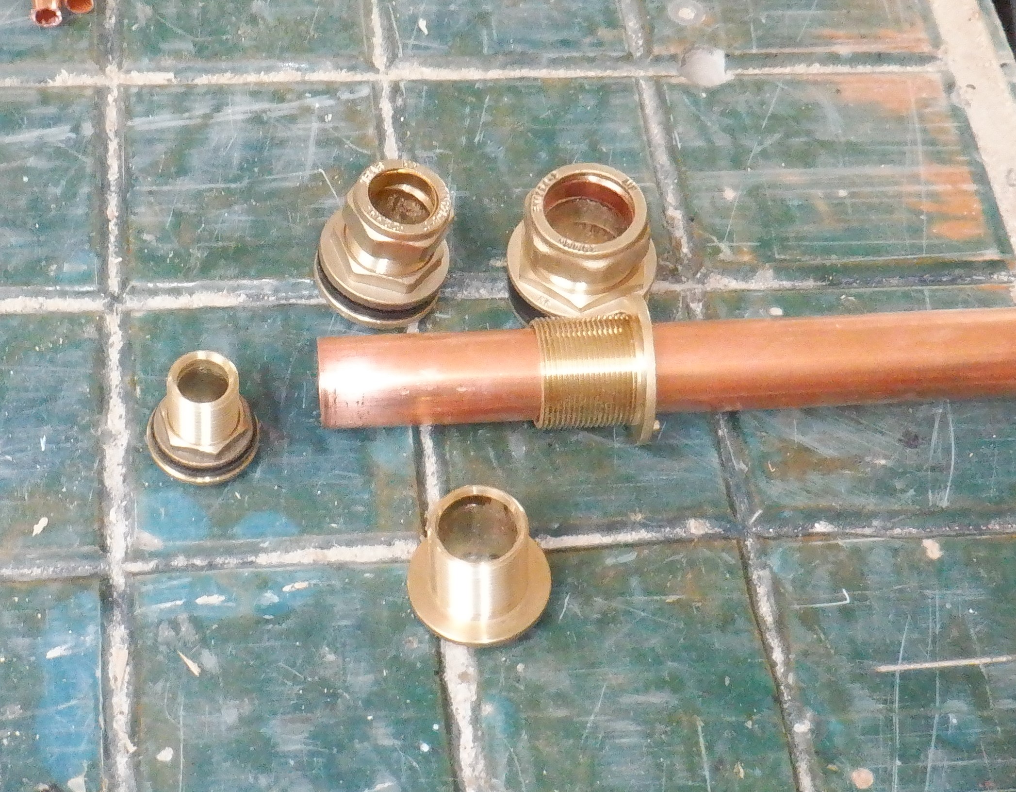
So we spent an hour or so fiddling with T-junctions, adapters, shut-off valves etc.
Here is the exact mapping of the Cold Water System:
- Header Tank feed (Blue 32mm pipe coming along under the floorboards)
- A adapter with a 32mm compression joint, converts down to 1inch BS Male Thread, with built-in shut-off valve
- Flexi-pipe, female to male 1inch threads
- Water pump, both input and output are female 1inch thread (provides up to 3bars of pressure)
- Flexi-pipe with male to female 1inch thread (allows the motor to be removed)
- Shut-off valve with 1inch male and 1inch female threads (these valves allows isolation and removing of pump for servicing)
- A nipple, all male 1inch threads
- Non-return valve with double ended female 1inch threads (maintains the pressure in the system)
- A Nipple, all male 1inch threads
- T-junction, all female 1inch threads, connected to the sideway middle branch
- Upwards is the Pressure Vessel with its 1inch male Thread
- Downwards is digital flow sensor with double ended 1inch male threads
- T-junction, all female 1inch threads, connected to upper branch
- Sideways is the Digital Pressure Sensor to provide feedback to the controllers, with adapter
- Downwards another T-junction, all male 1inch threads, connected in upper branch
- Sideways to a shut-off valve with an 1inch female threads, which the other end being an 1inch male thread and has an adapter to convert to 22mm compression joints for domestic plumbing pipes
- Downwards connects to right angle adapter with female 1inch thread to a 32mm compression joint (to go horizontally at the bottom of the cupboard)
- Short length of blue 32mm pipe
- T-junction with straight two 32mm compression joints horizontally and side branch a female ¾inch thread
- Sideways to adapter(s) to connect a drainage stop-cock.
- Onwards to blue 32mm pipe and starts its journey around the house!
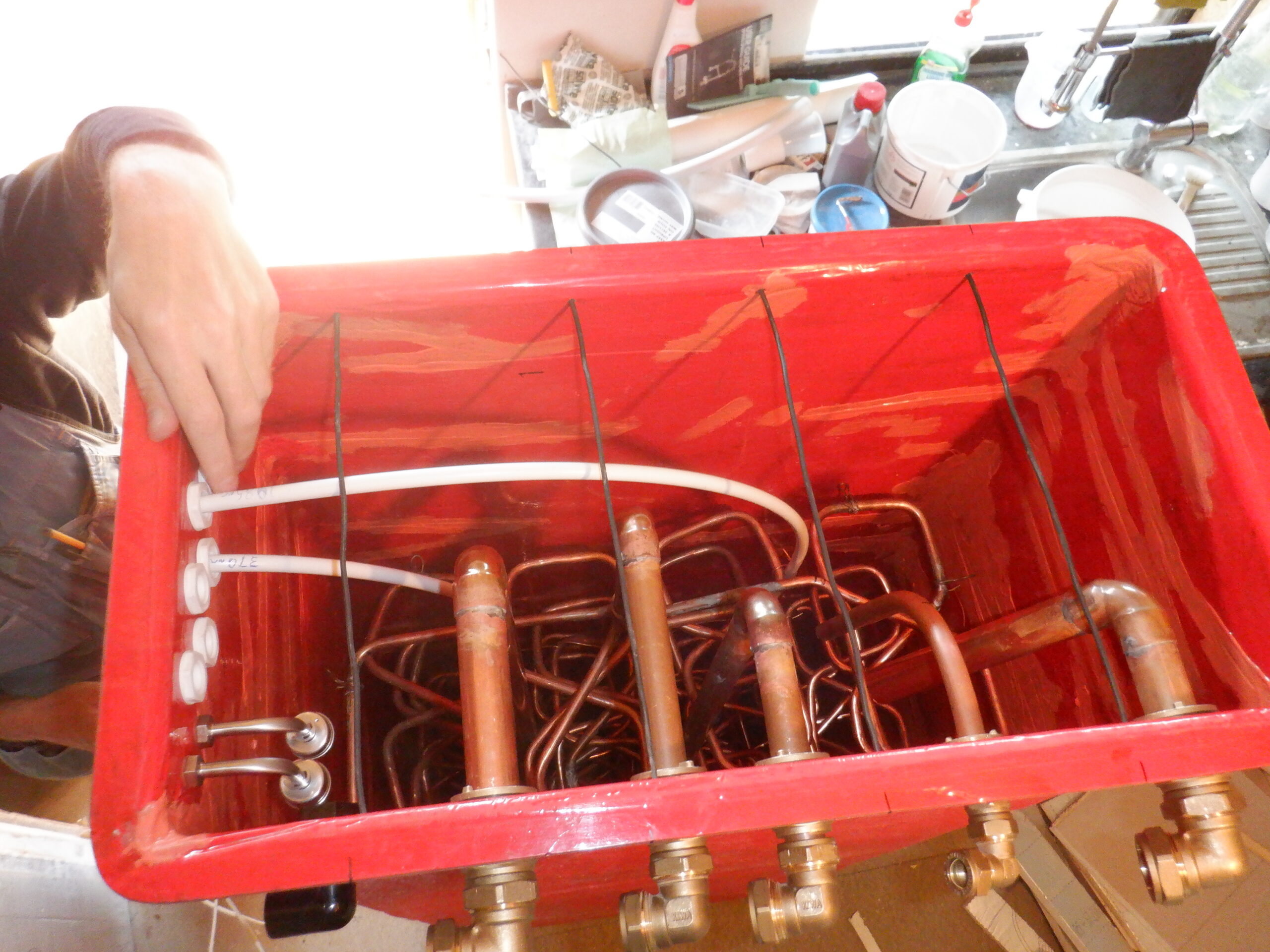
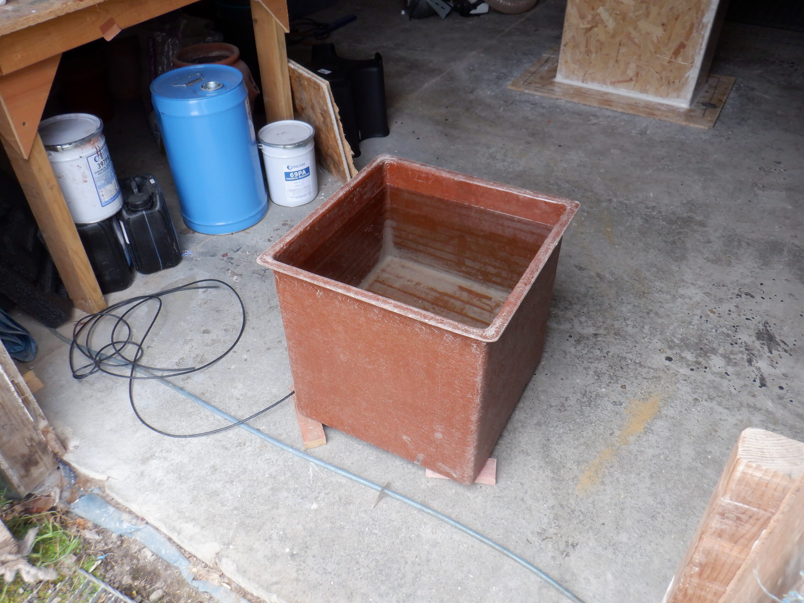
And here is a picture of our first play in arranging all those parts !!
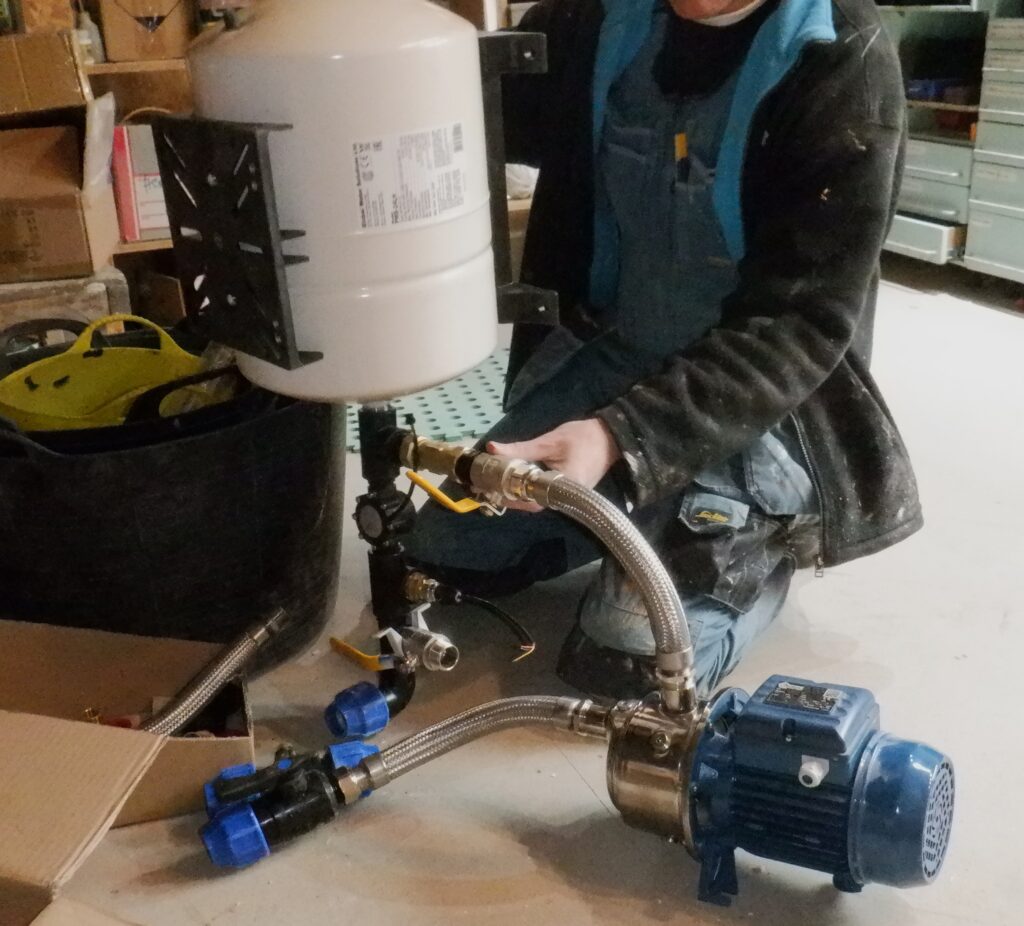
Trying out cold water pressurisation parts
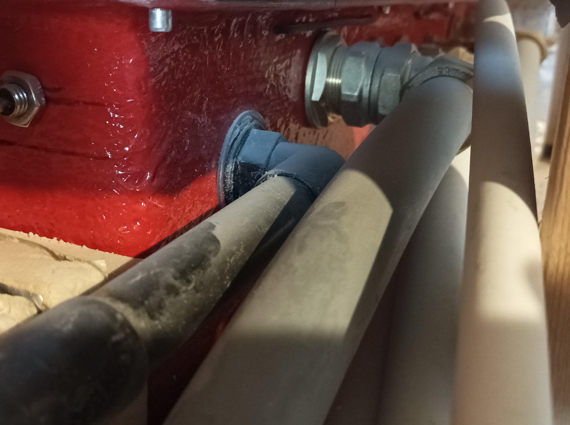
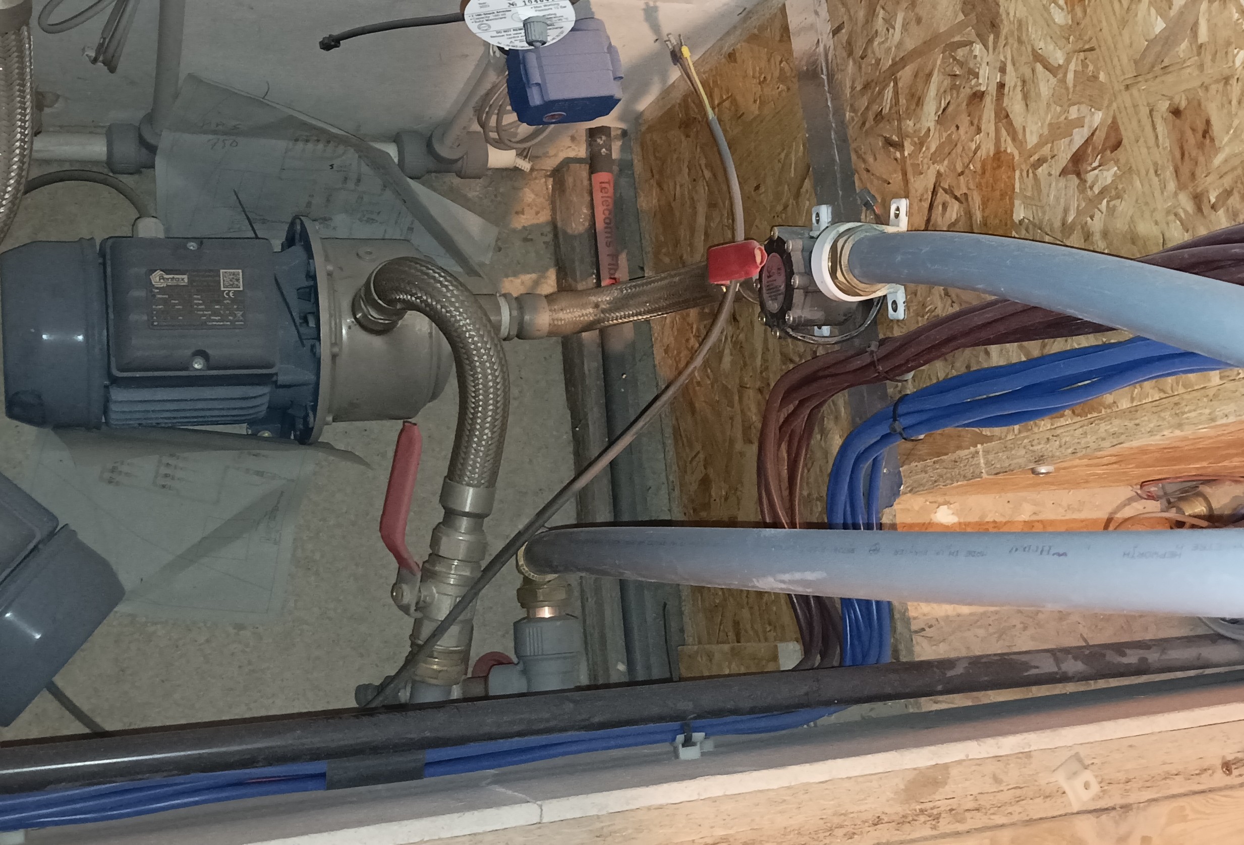
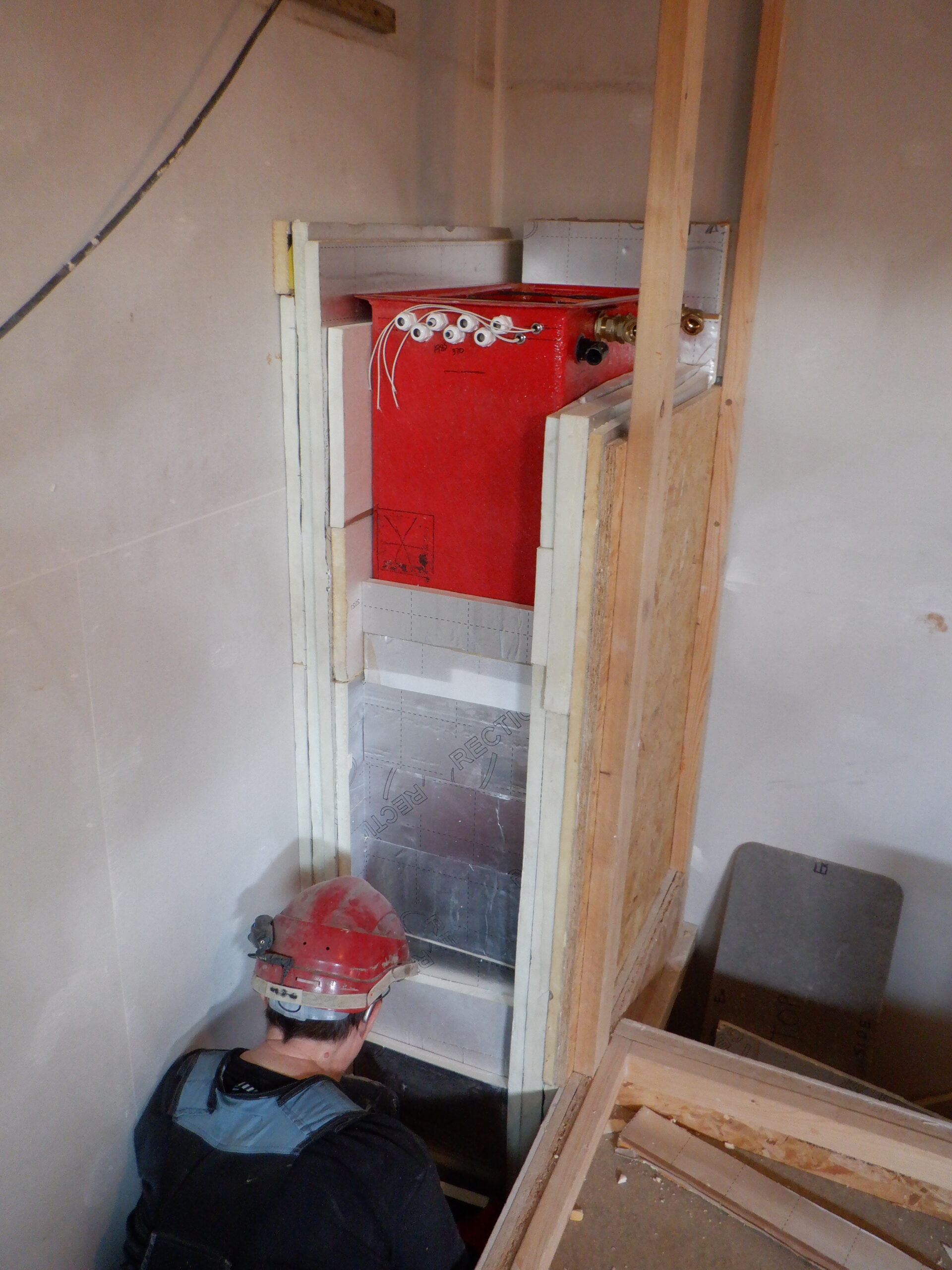
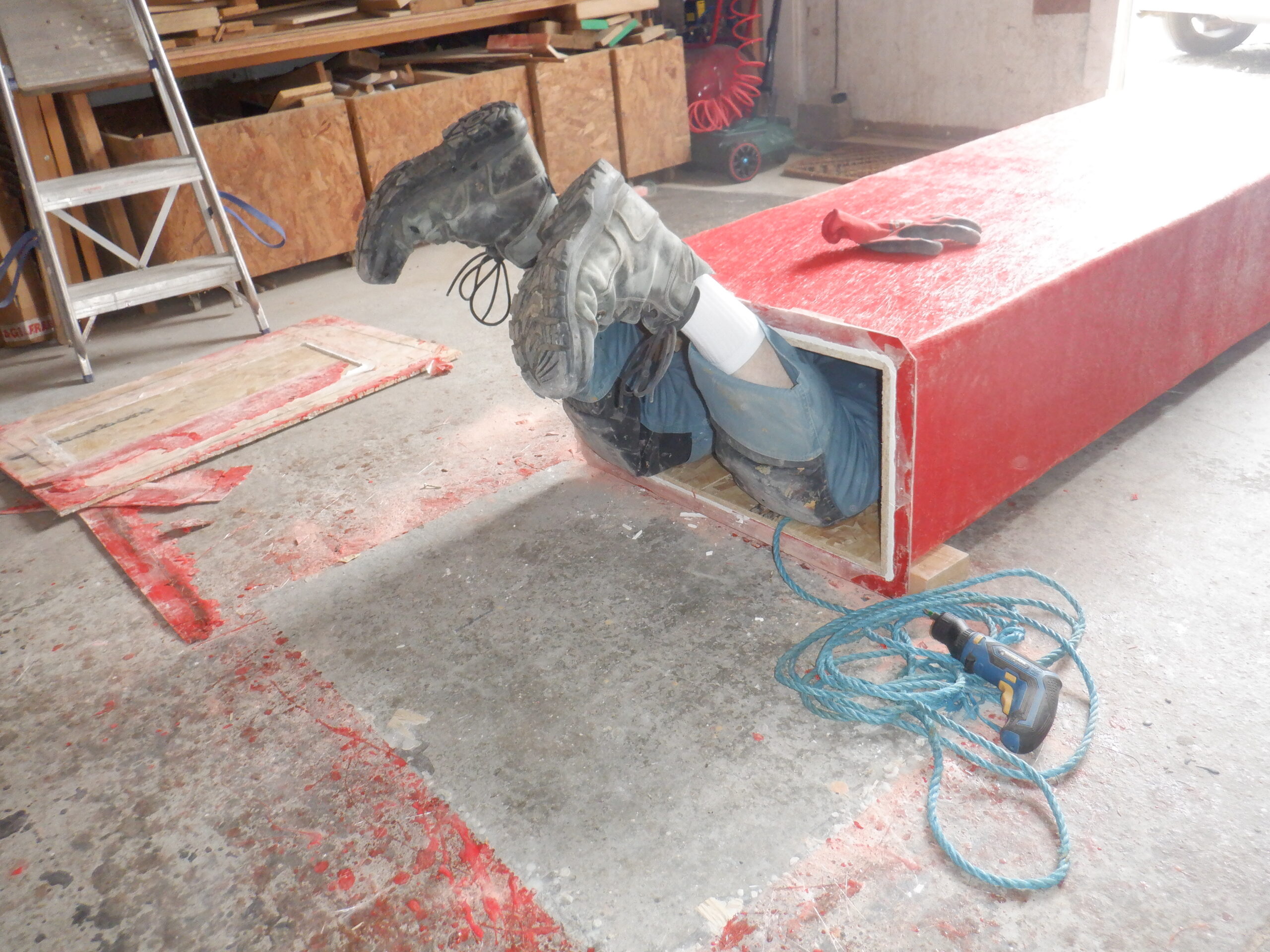
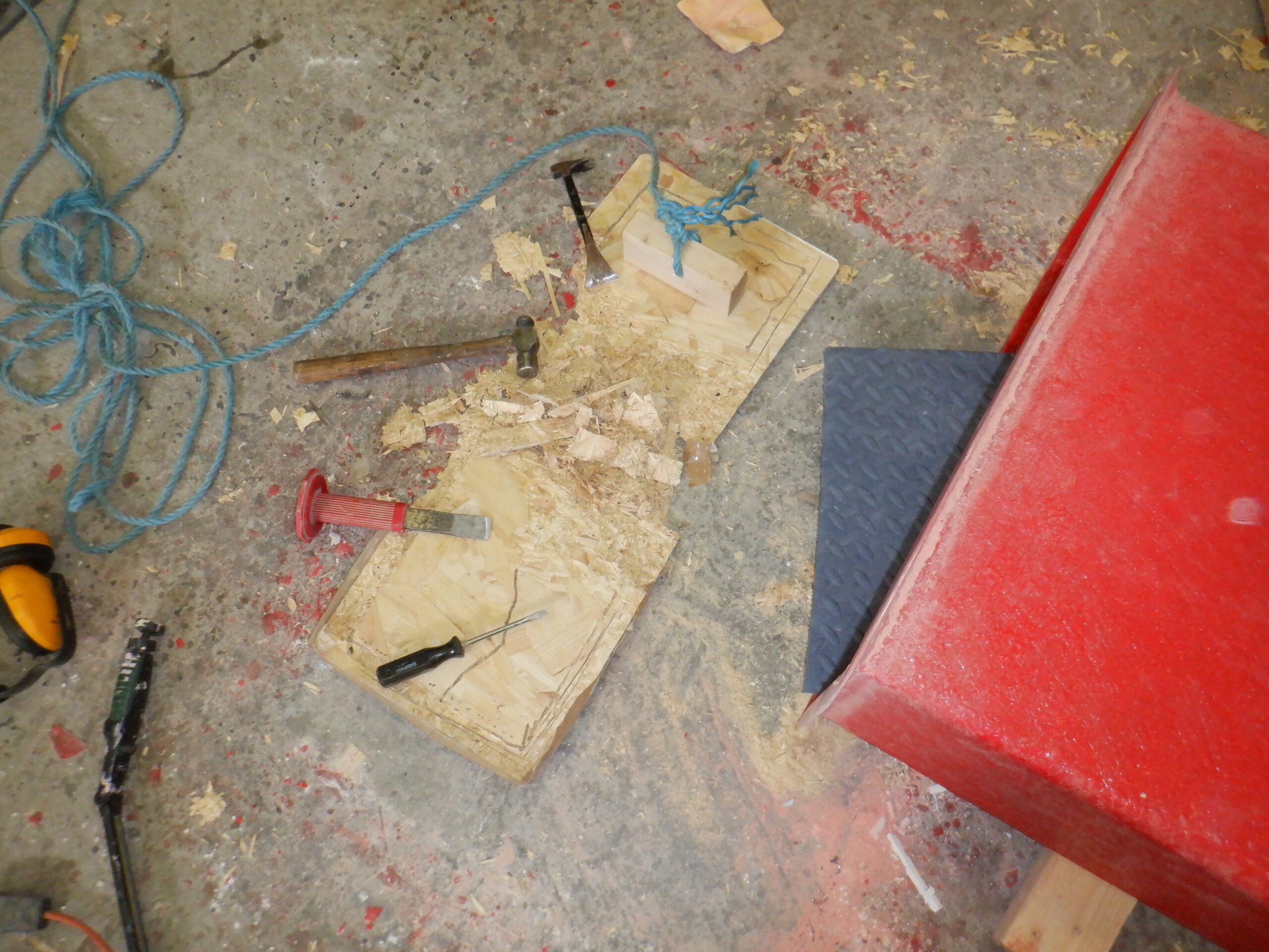
After getting the Header Tank sealed against those leaks, plus also completed the first stage of building the ventilation ducting inside the Utility Cupboard, we implemented our plumbing matrix as stated above and physically installed the various parts next to the new ventilation duct. We screwed on the expansion vessel first and then used LSX thread sealing liquid on each joint on each part as we went through the design, including the electric pump which was bolted down to the solid concrete floor. The input from the header tank was joined in this network, the 32mm wide blue plastic pipe coming through the cupboard wall beneath the floor level, and then the output pipe which is also blue and 32mm diameter, came out the cupboard in a similar position but went off to the space underneath the sink, to join up with the existing water pipe that is travelling around our house, going from room to room.
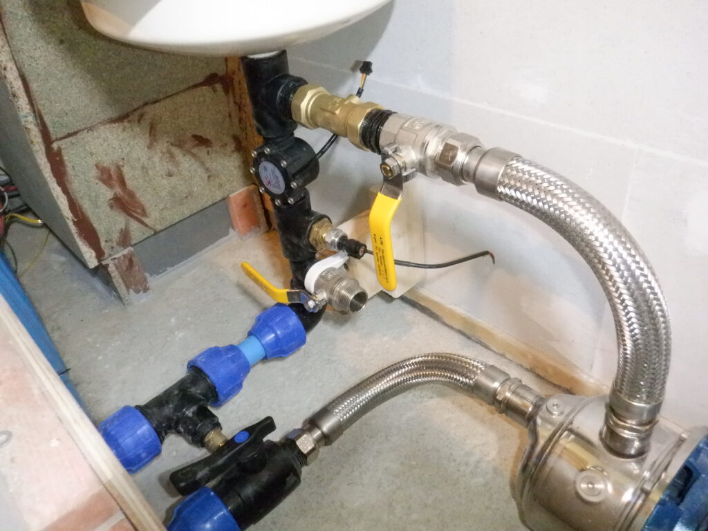
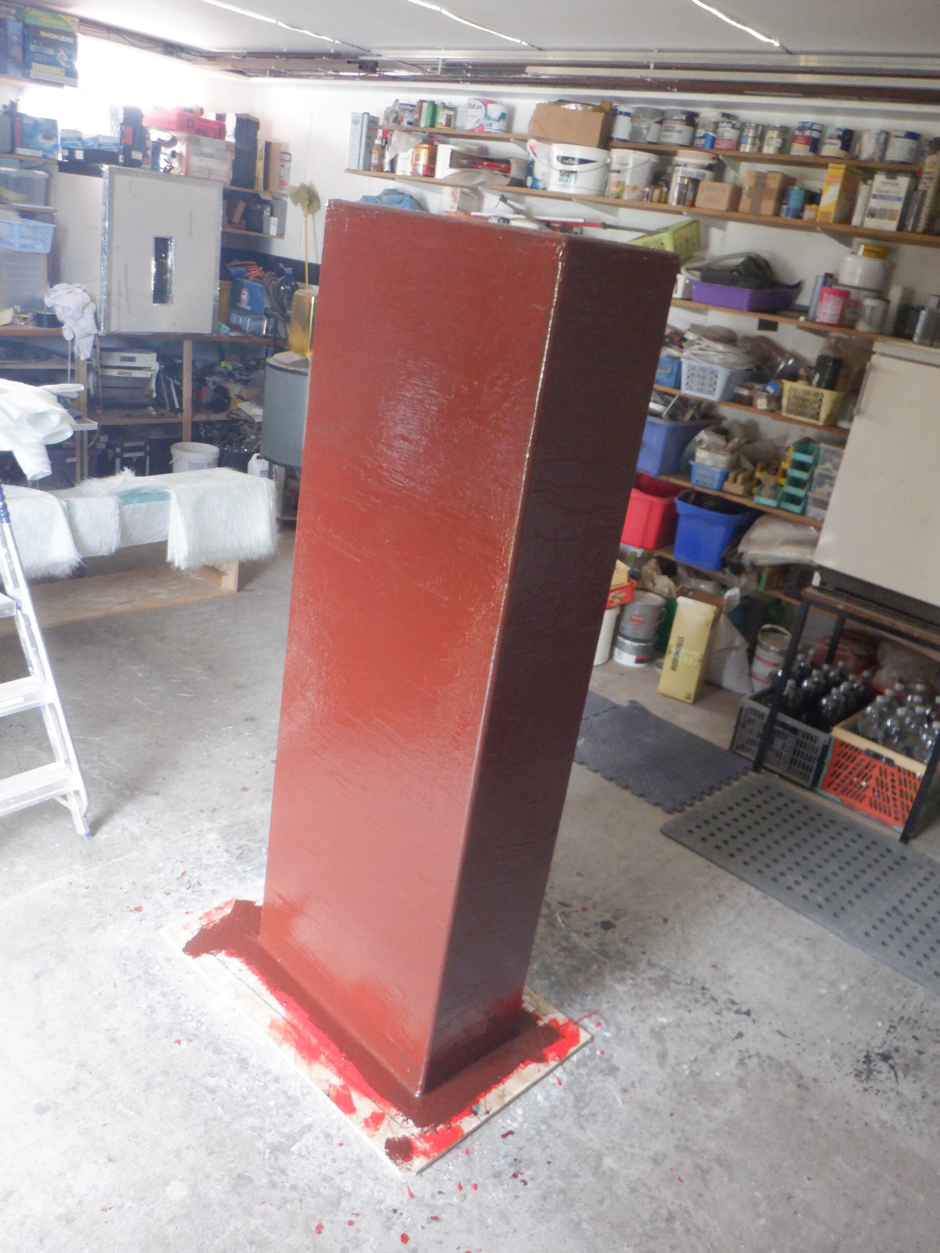
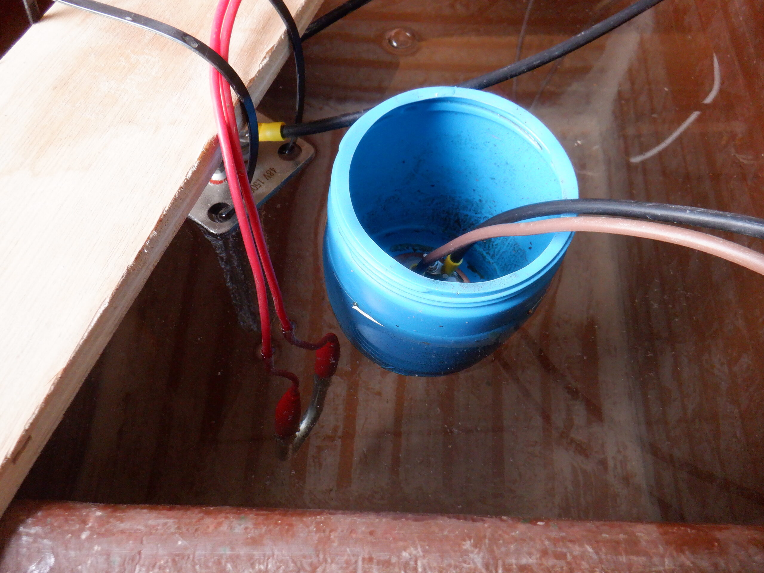
Cold water pressurisation system 1

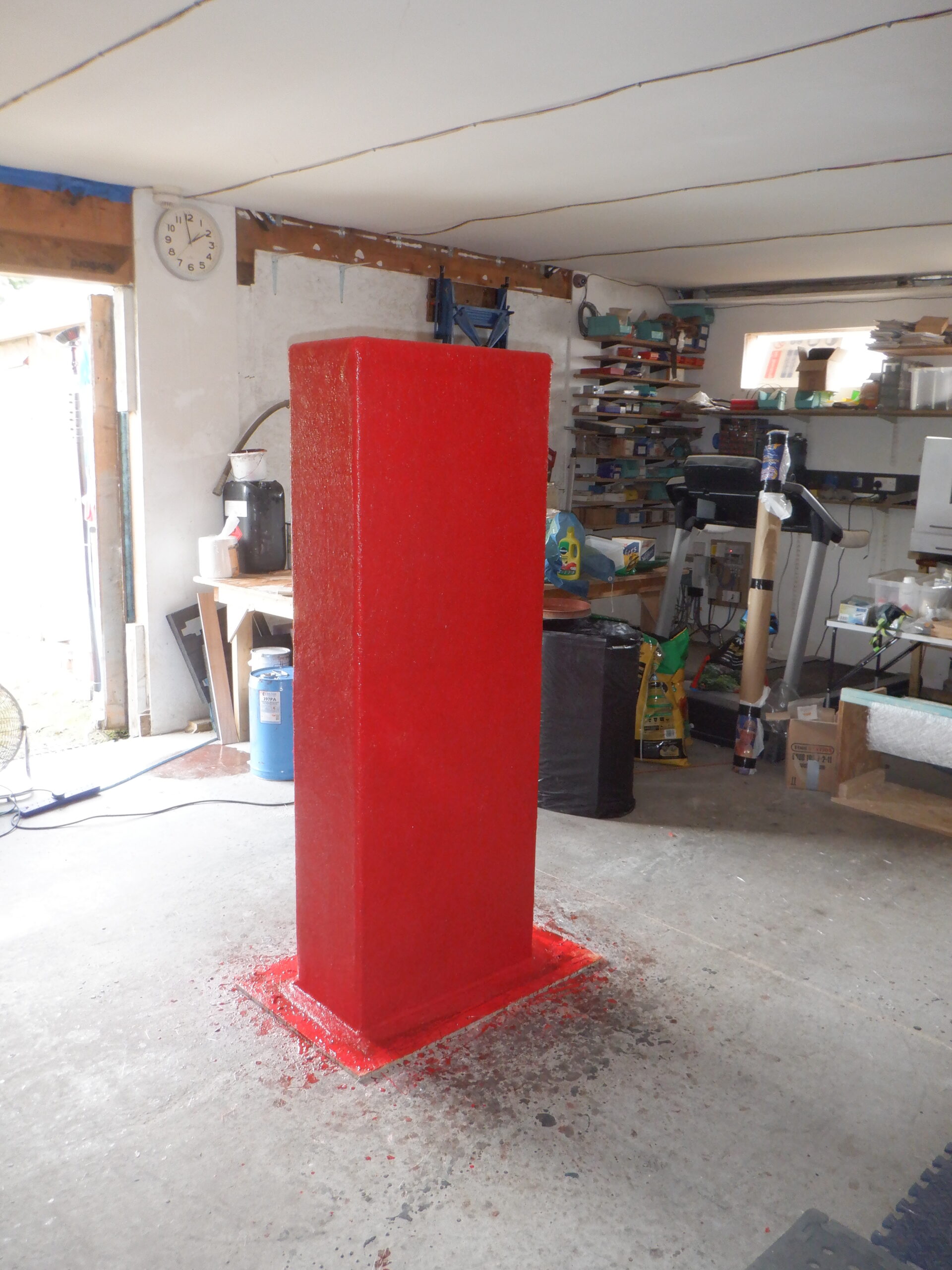
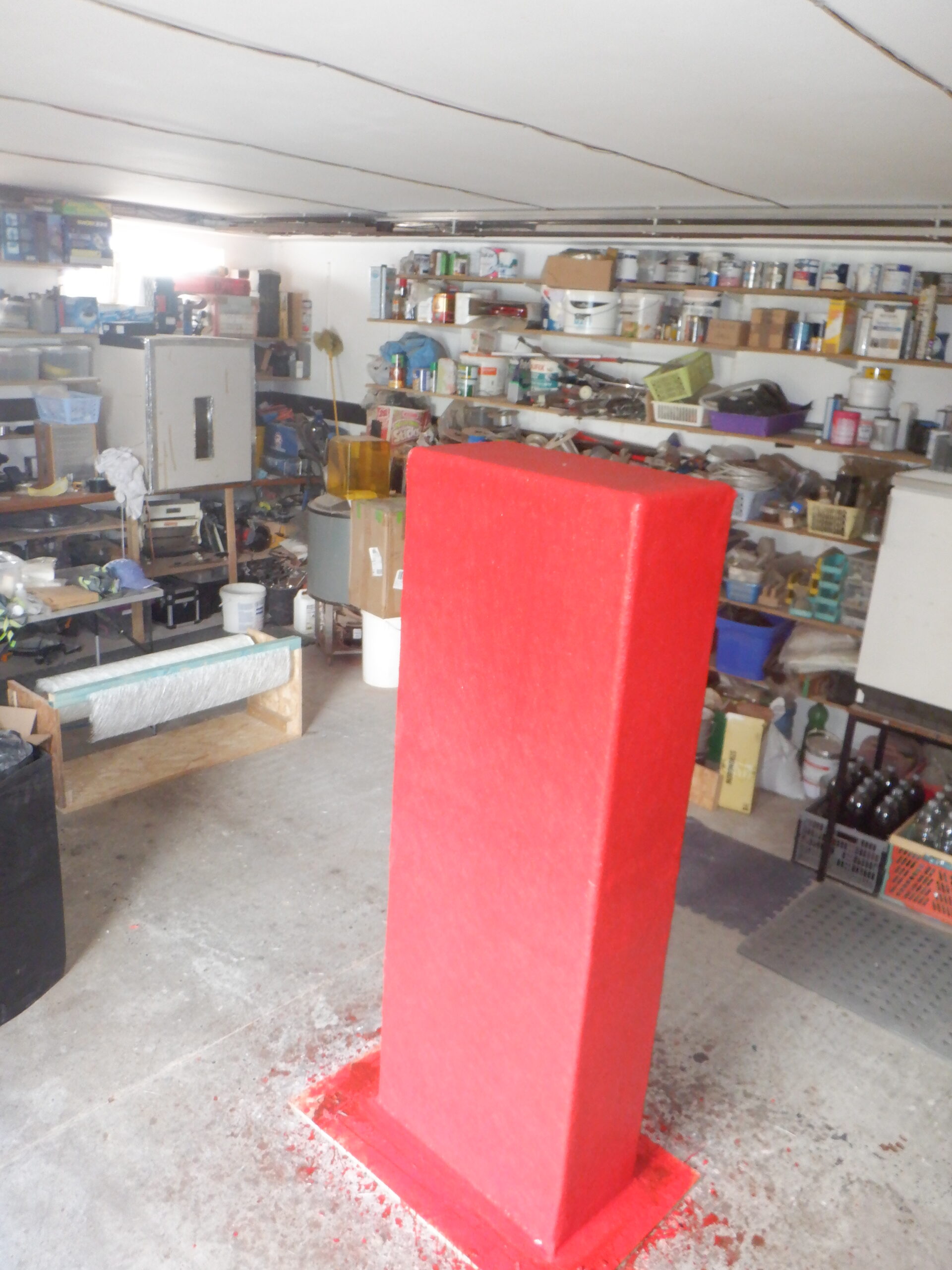
Cold water pressurisation system 2
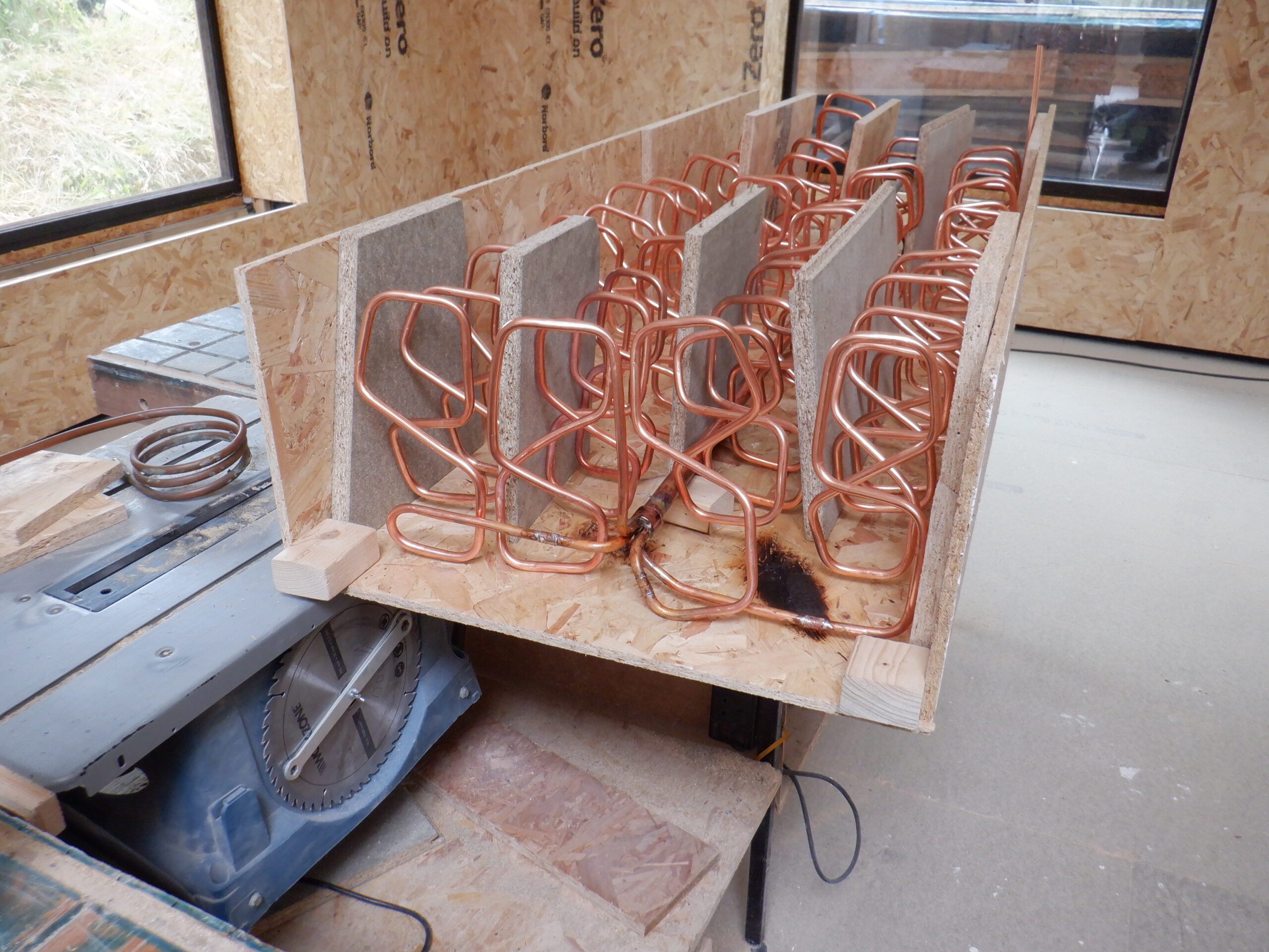
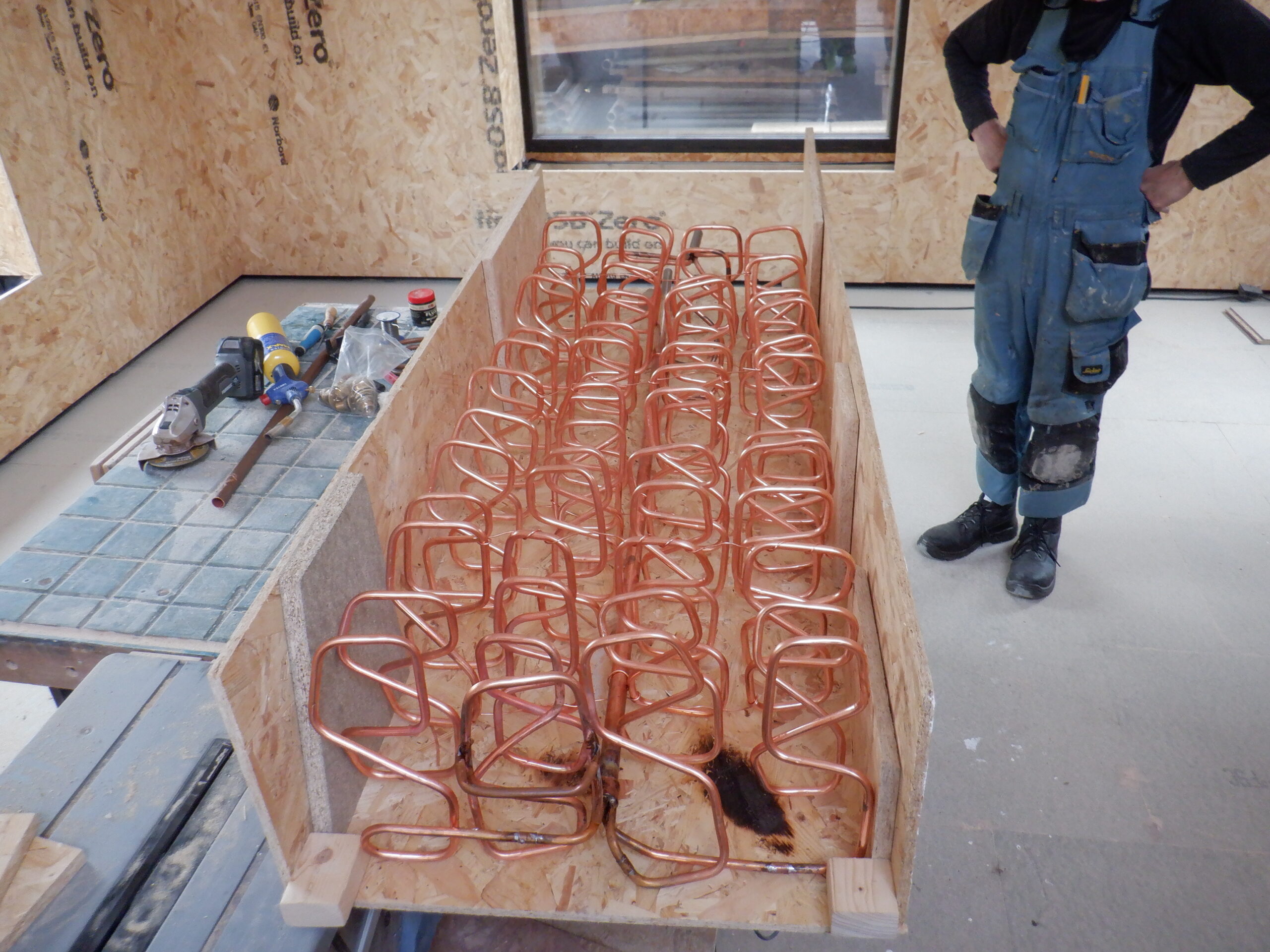
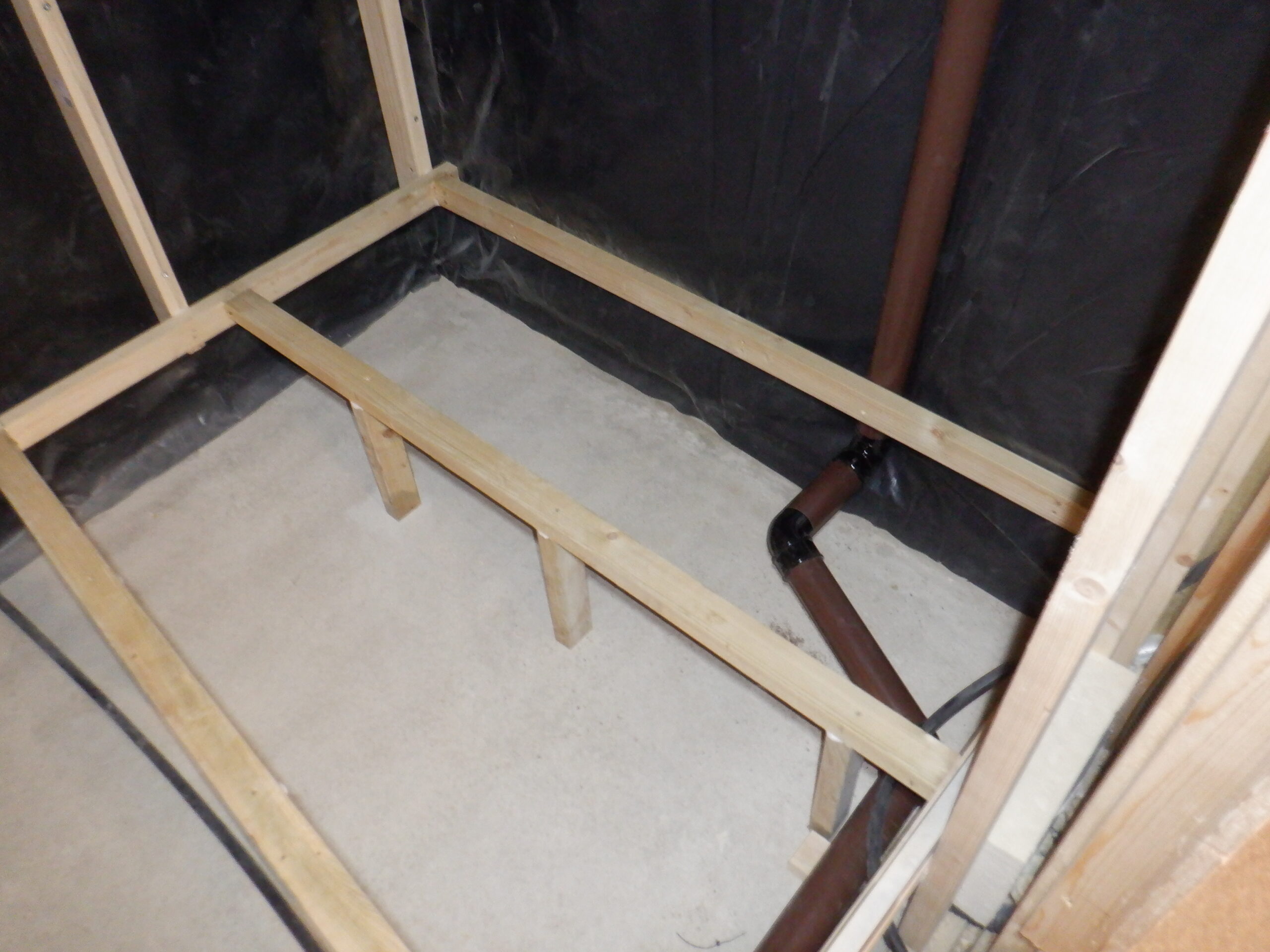
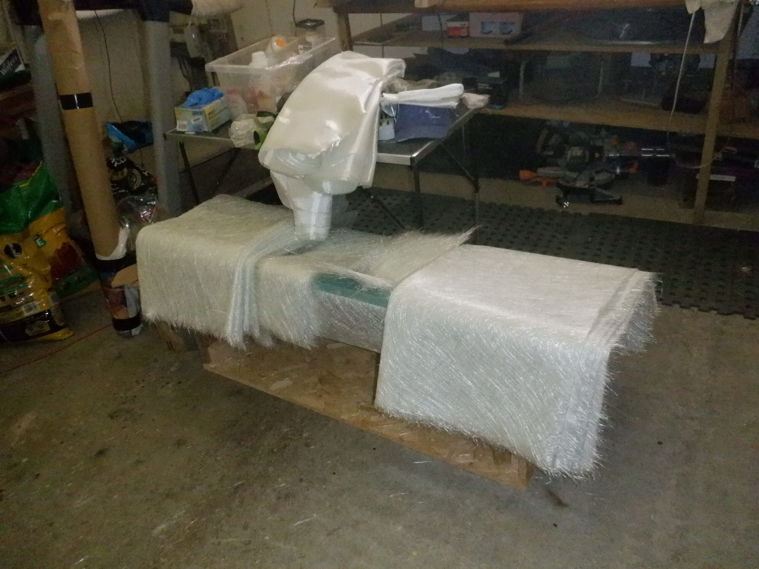
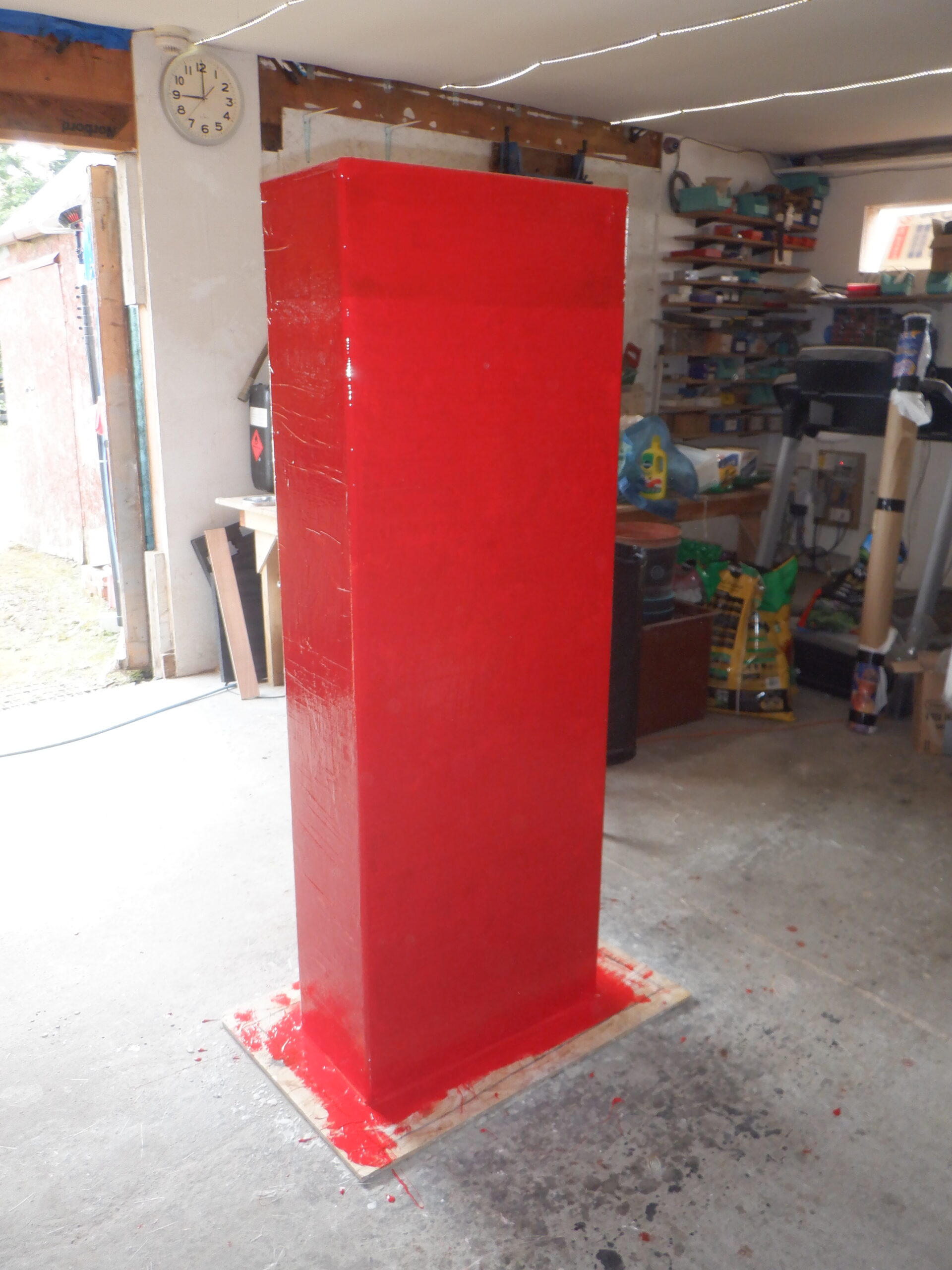
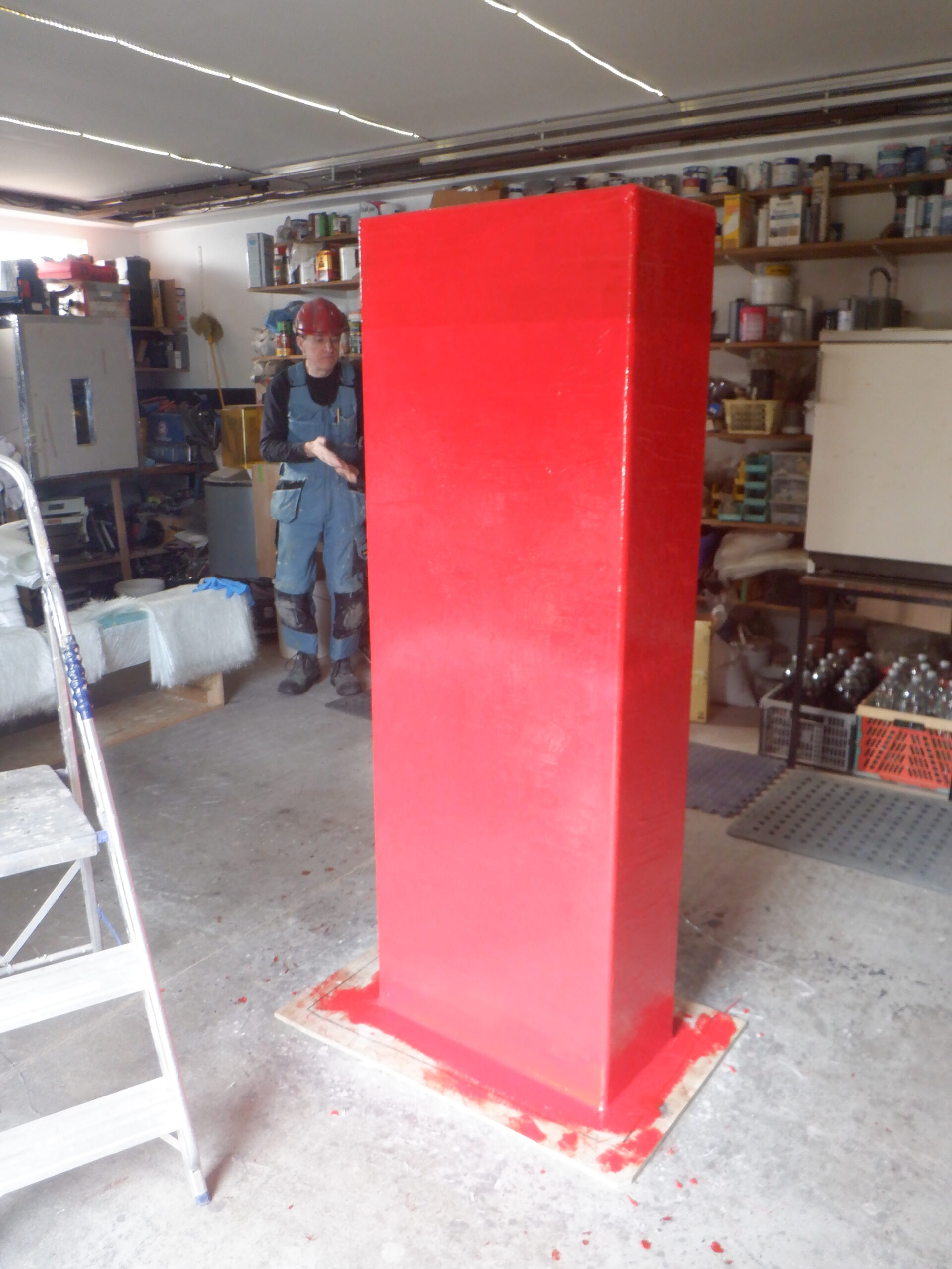
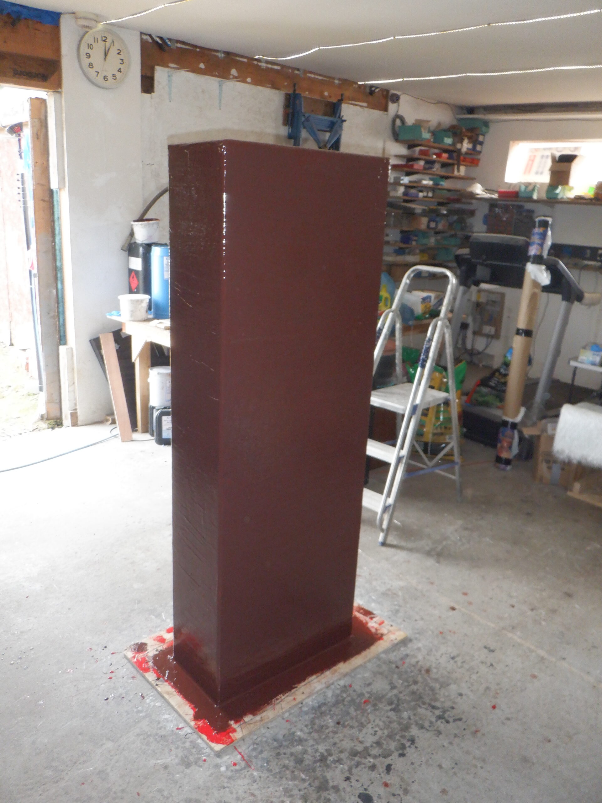
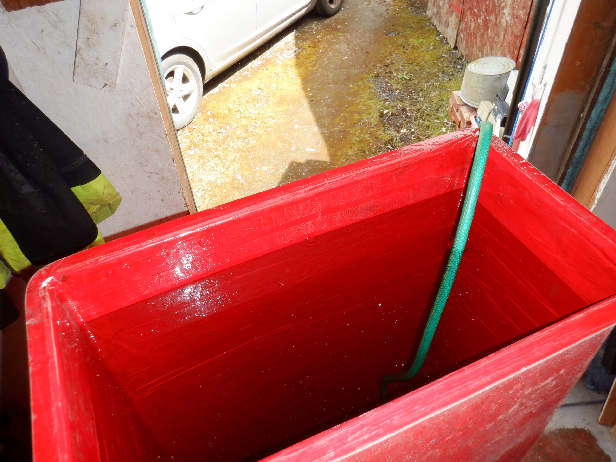
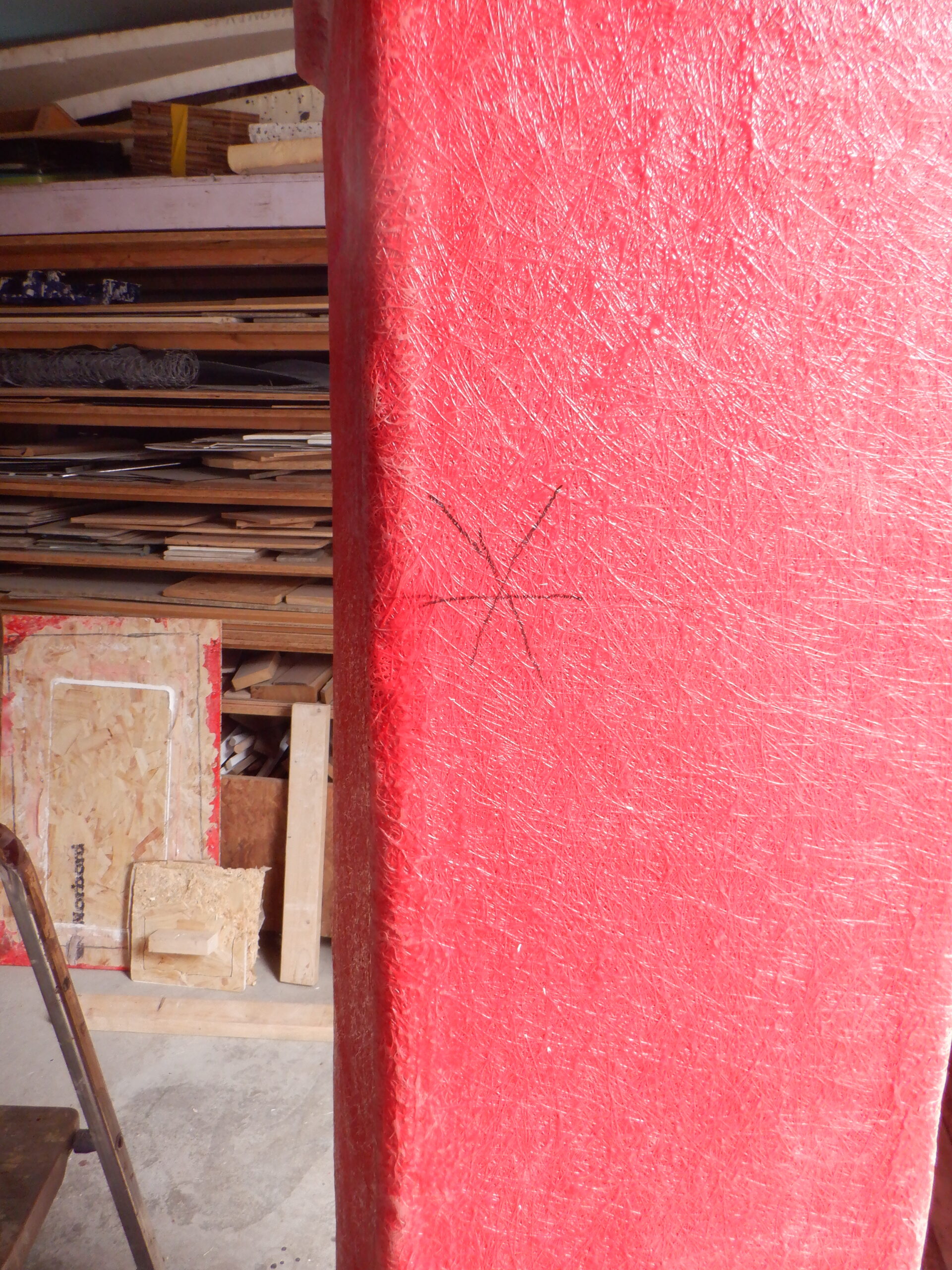
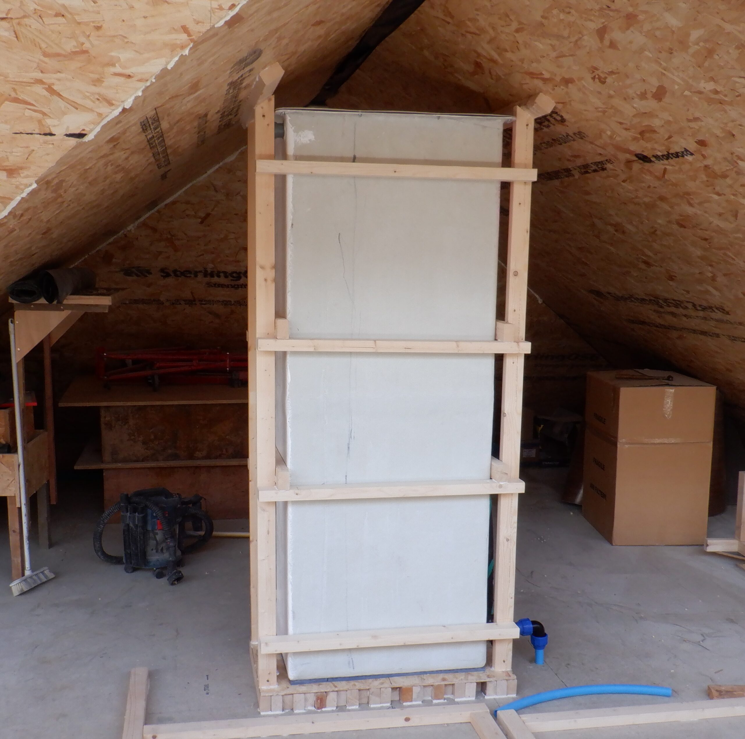
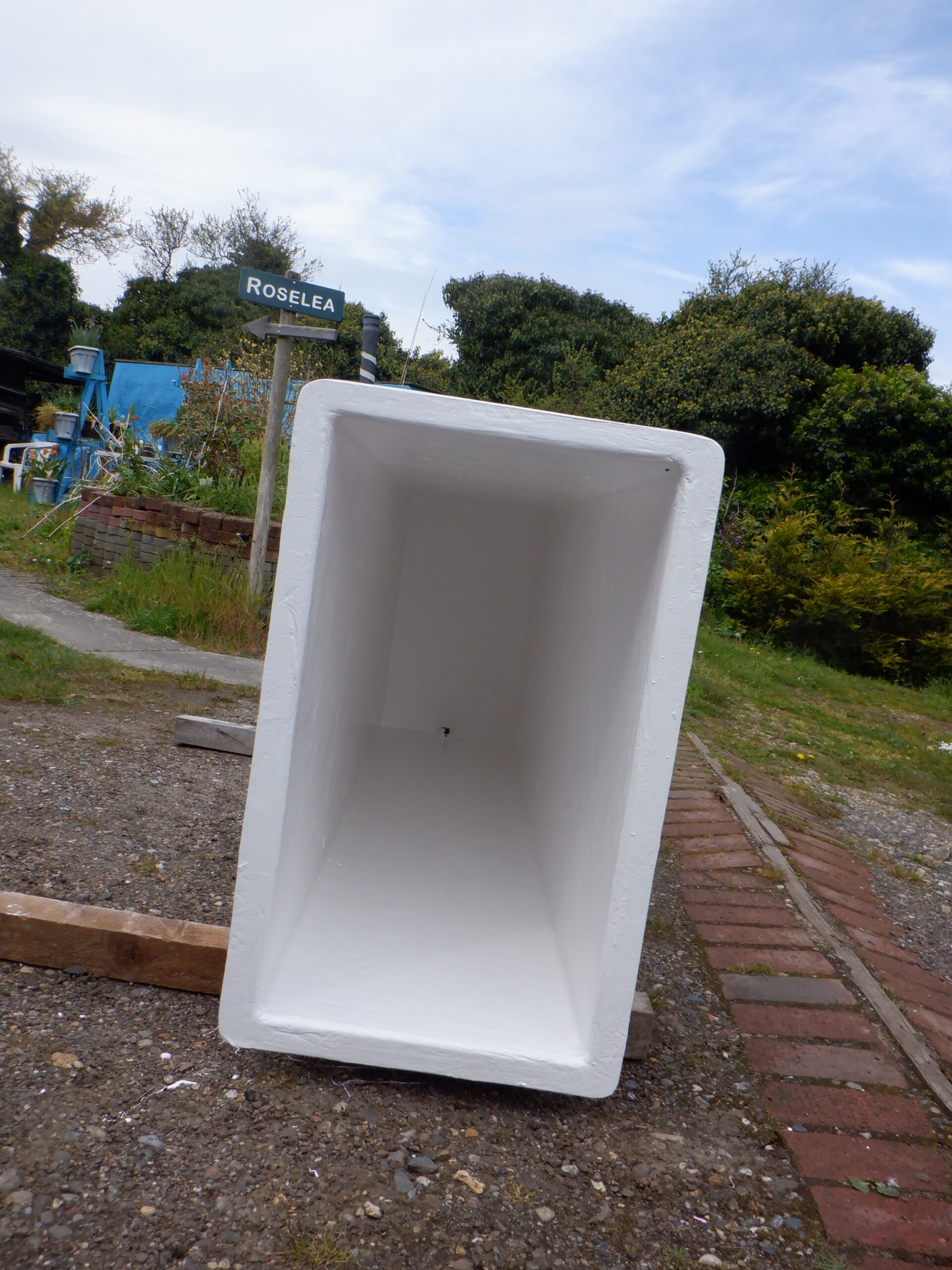
The next job was to install our new Cold Water Header Tank upstairs, placing it on the prepared platform and then proceeded to build a wooden framework around the entire tank, putting four legs in each corner, attached at the both the bottom and top, glued and screwed into place. Then, putting four horizontal 63mm CLS wooden bars across the wider faces, evenly distributed and doing the same on the other wider face as well. Finally, we slid in two connecting pieces of timber, to join the front and back frameworks together, to help stiffen up the entire cage surrounding the tank.
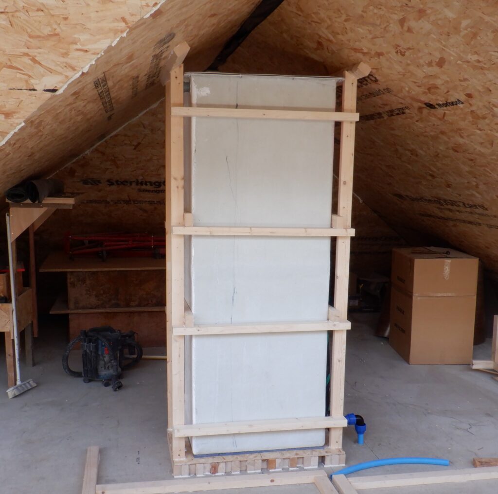
Header tank in place and Framed
We then connected the blue pipe to the tank connector we had already installed at the base of the tank, including a shut-off valve too. This pipe is the gravity feed that goes down to the space under the hallways, turning the corner and heads to the Utility Room and our assembled motor and associated equipment. This also included a T-junction half way along this pipe, under the flooring, just located at the crossroads in our Hallways, this branch will go off to our ground floor WC and also distributed to all our fire suppression system. We wanted to make sure that these services still work, even when we had lost power or control over our motorised valves and pumps. It is purely based on the good old reliable gravity feed from the header tank. It might be slow but it will still provide a toilet that will flush and the spray nozzles will still inject fine droplets of water during a fire breakout.
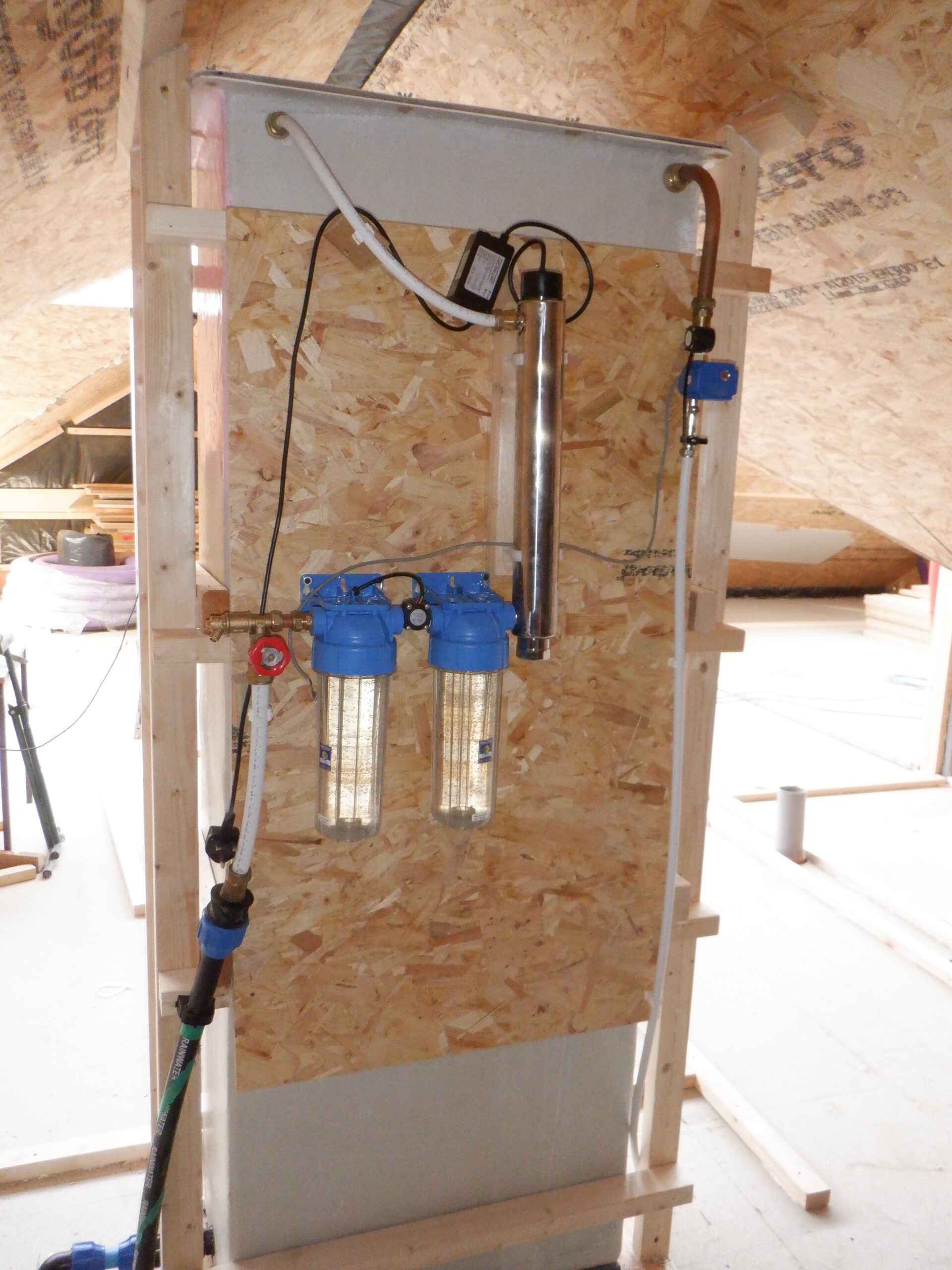
Another job is to connect the “Green and Black” rainwater pipe to the Header Tank, via the filtration and sterilising units, which we mounted on a piece of 18mm thick OSB board that in turned is mounted to the framework around the tank. The 32mm Green pipe is converted to a 22mm plumbing pipe, which in turn goes into a flow-control valve, a drainage valve, enters a particle filter that removes solid bits down to 1micron across and then through a second filter, this time, an activated charcoal filter to remove chemical substances like the chemicals that the farmers used on their fields in our local district, which is blown up and carried by the winds to our slates on our roof, which is then washed off into our rain storage tank underneath the Garage. The third and final unit that this water passes through, is the sterilising that will kill viruses, bacteria and fundi, by bathing the water, and these floating invaders, with strong Ultra-Violet radiation. A similar system is also used for fish tanks and fish ponds.

Header Tank plumbing
We then connected up the pipework inside our Garage from the underground rainwater tank, to the 32mm black pipe that goes through the concrete floor slab and underground to the main house. It appears up through the concrete slab inside the Utility Room, under the sink and washing machine sections. We already had a pump sitting submerged at the bottom of the rainwater tank so we plugged it into a nearby mains socket and proceeded to run the pump and see how fast the water was flowing after travelling all the way from the Garage and right up to our header tank. We put on our test meter on the flow measuring sensor and it settled down to about 7Hz, which according to the standard formula for these types of flow meters, represents a flow rate of less than 1litre per minute. O Crikey, that is slow!! It would take ages to refill the Header Tank, after we had a shower, or ran a bath!! AND .. This is Before we had inserted the two filter modules themselves! So, after examining the specifications of our existing pump, we are buying a replacement submerged pump, the next model up, going from 250Watts to 500Watts in electrical power. This is probably a overkill but we had no choice. But, we will see later on when we have changed over the pump, inserted the two filters and then measure the flow rate again.
So while waiting for the pump to arrive, plus also other bits and pieces of plumbing parts, we got on with another task. This time, we went around putting shut-off valves on each T-junction on the blue 32mm Cold water pipe that is going from room to room. We lifted up each hatch that allow access to the plumbing valves and other pieces of equipment, and connected a 22mm inline shut-off quarter turn valve. We carried on doing that from location to location, moving around the house. We did Bedroom Three, Bathroom, Bedroom Two (after having to move the entire stack of sheet material first – Phew!), Bedroom One, then the Great Room (where we had to install two T-junctions on either side of the air duct) and finally, terminating in the Kitchen (where we had to slice into our floorboard to make two little hatches that hadn’t been done yet).
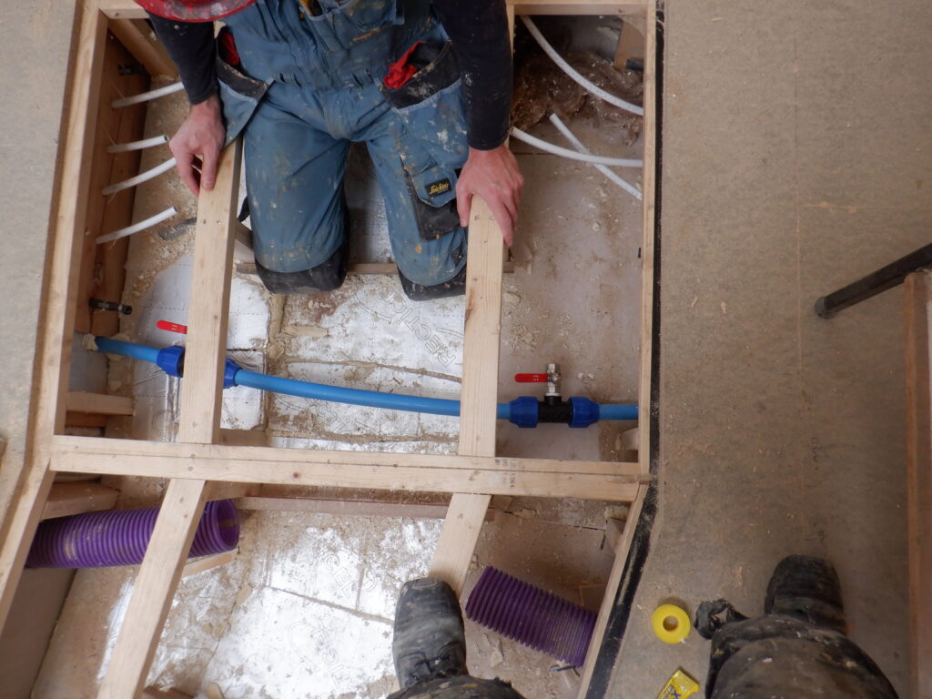
Cold water outlets in Great Room
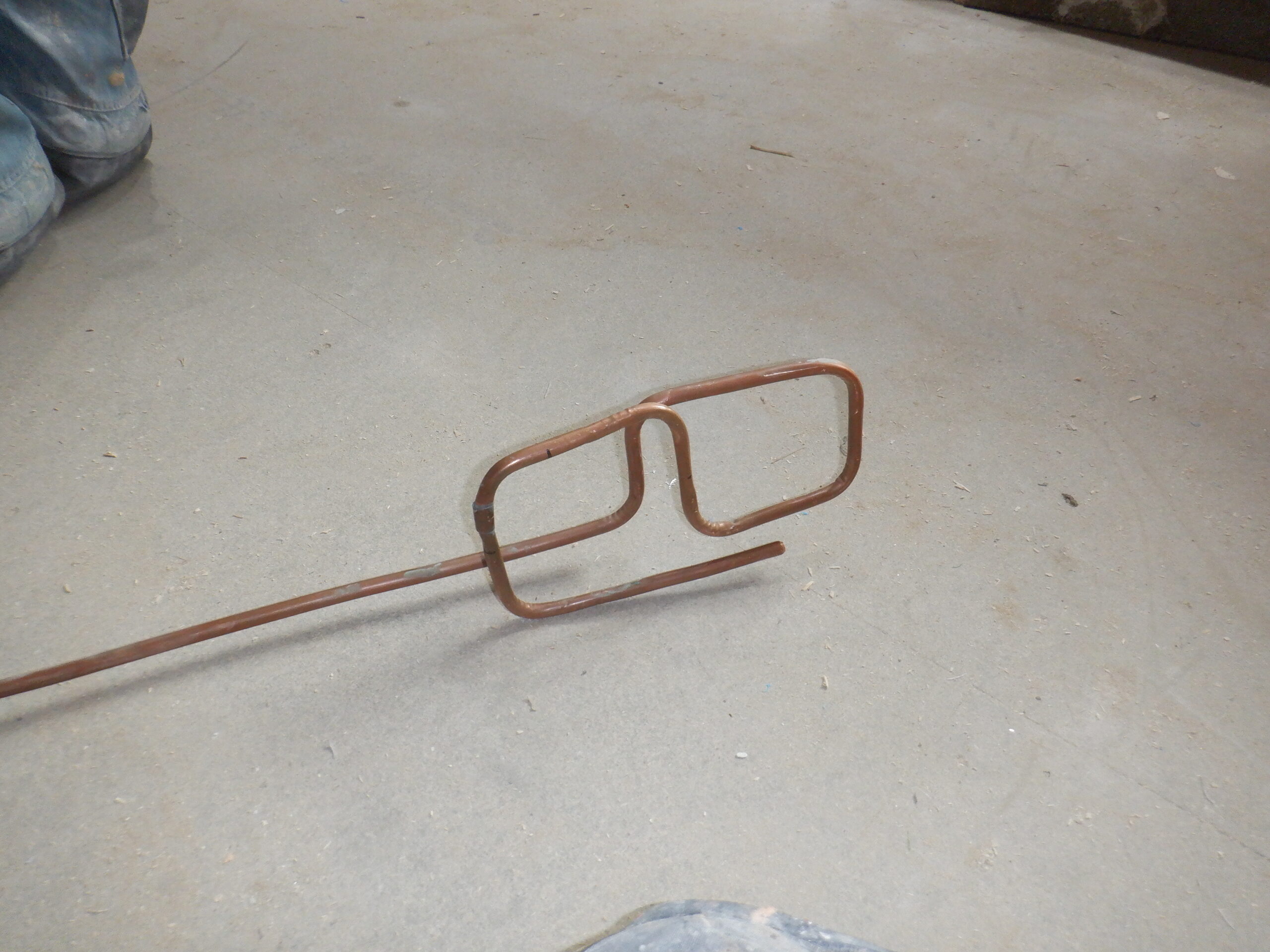
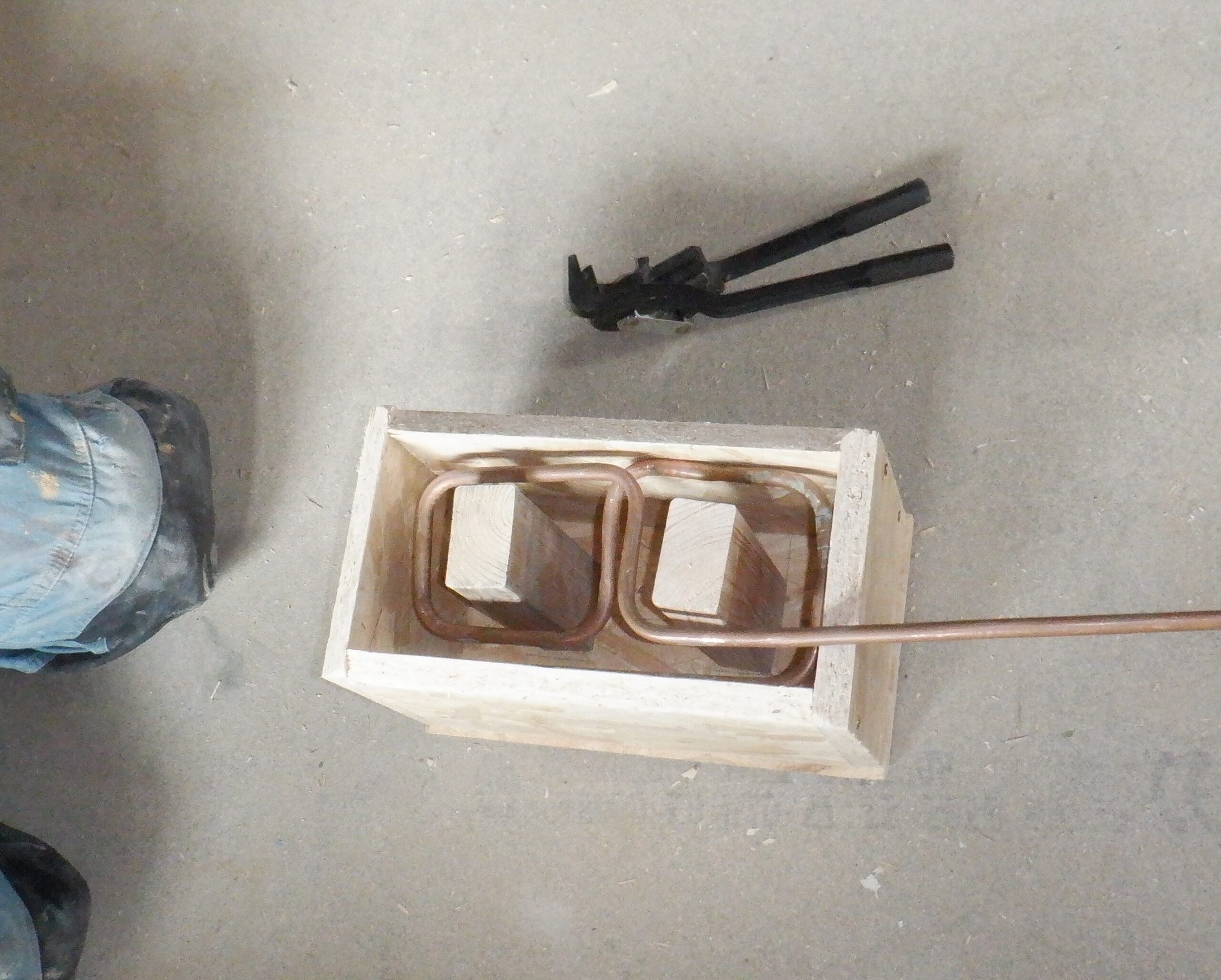
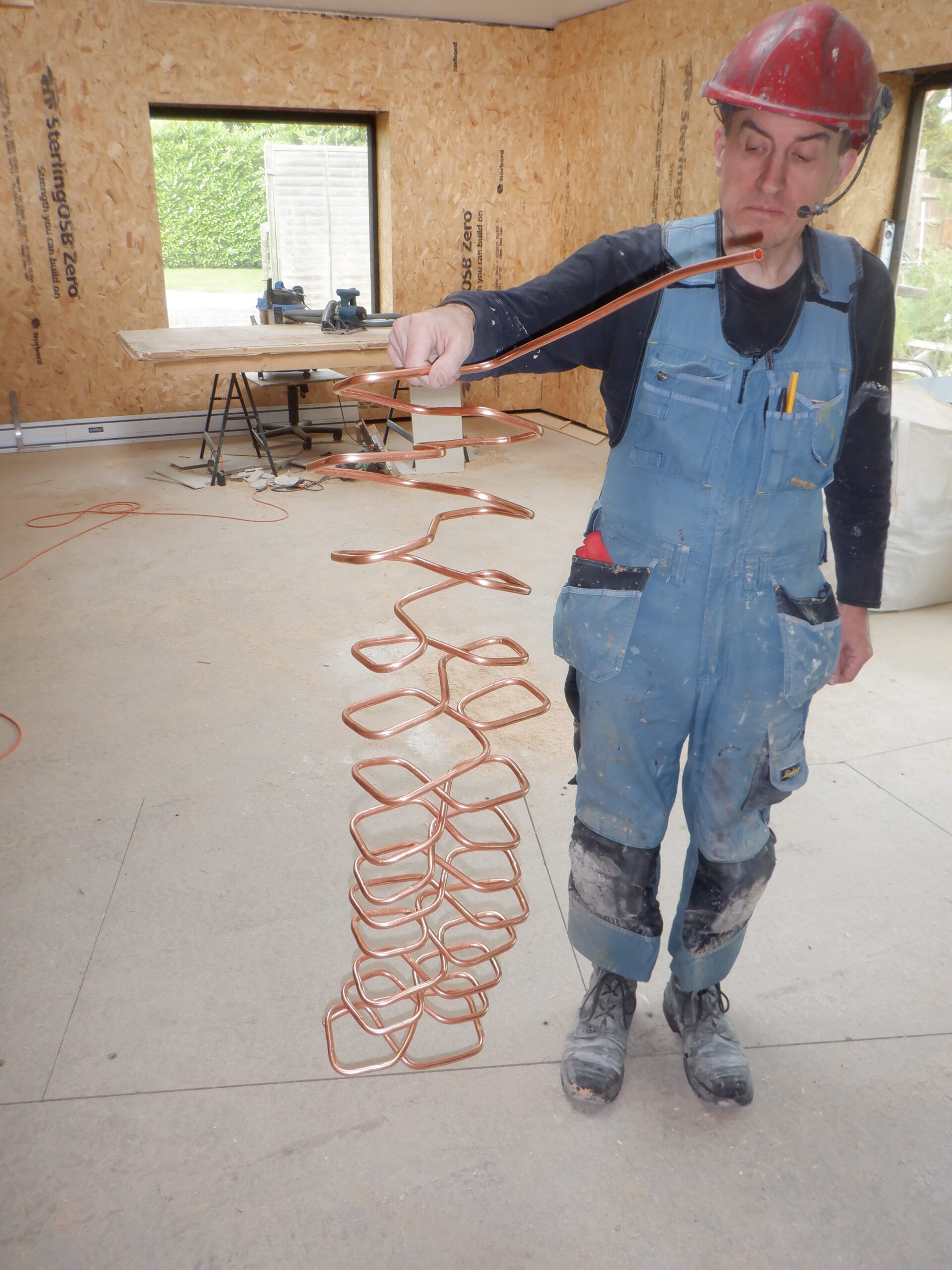
Another plumbing job was to take a tap off the mains water 15mm pipe that is running down the hallway (which is going off to the Kitchen) and this branch line goes up inside the wall and pokes up beside our new Header Tank and connected into a series of items, as follows, a shut-off valve, a non-return valve, motorised valve and a flow rate sensor, before a final 22mm diameter copper pipe is bent and enters the Header Tank. This connection will provide a backup method of putting water into our Header Tank, against those times that we have ran out of rainwater. The computer will monitor the level inside our rainwater tank, and automatically switch over to using the mains water supply. Hopefully, this would only happen during very long droughts in the Summer months.
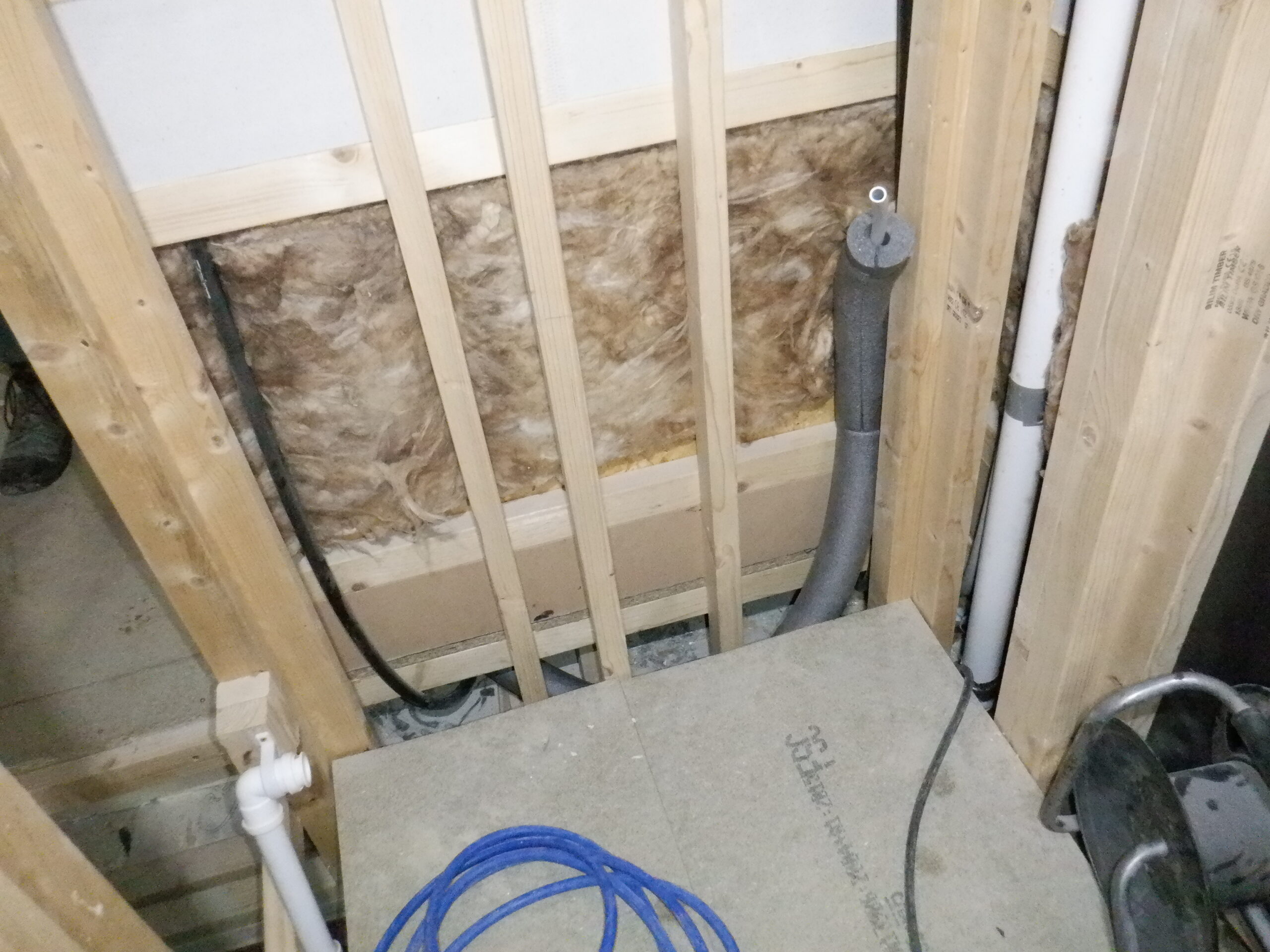
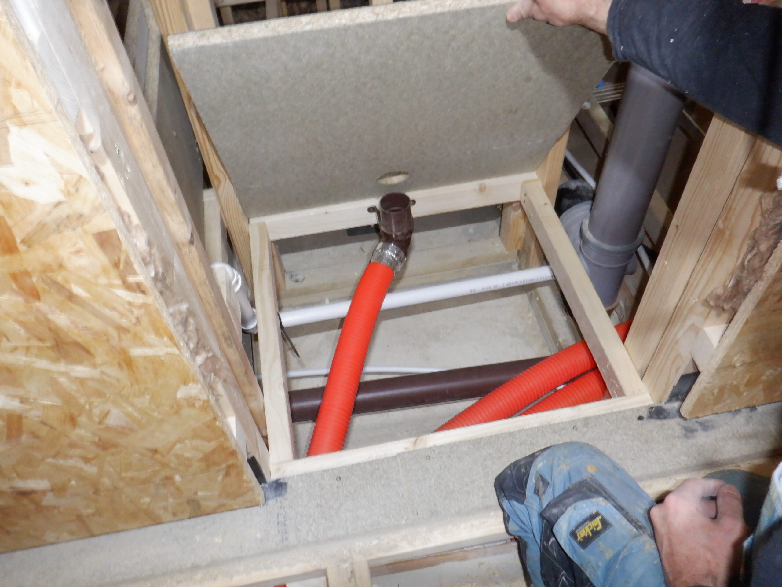
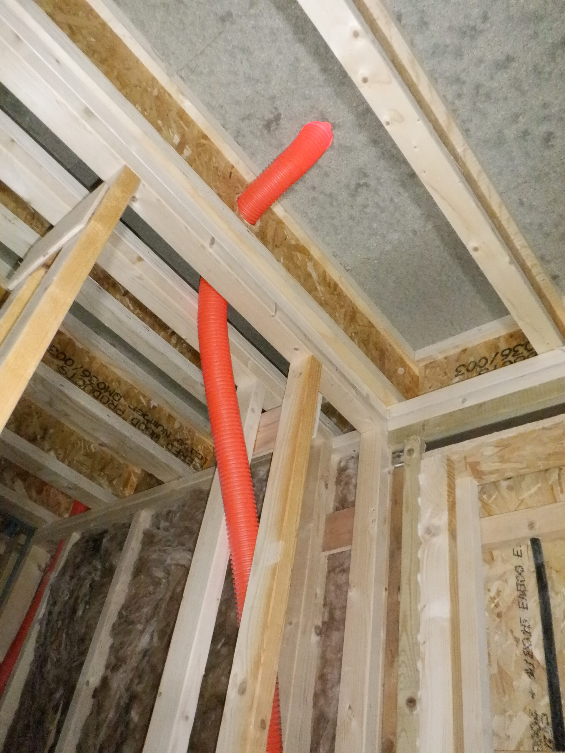
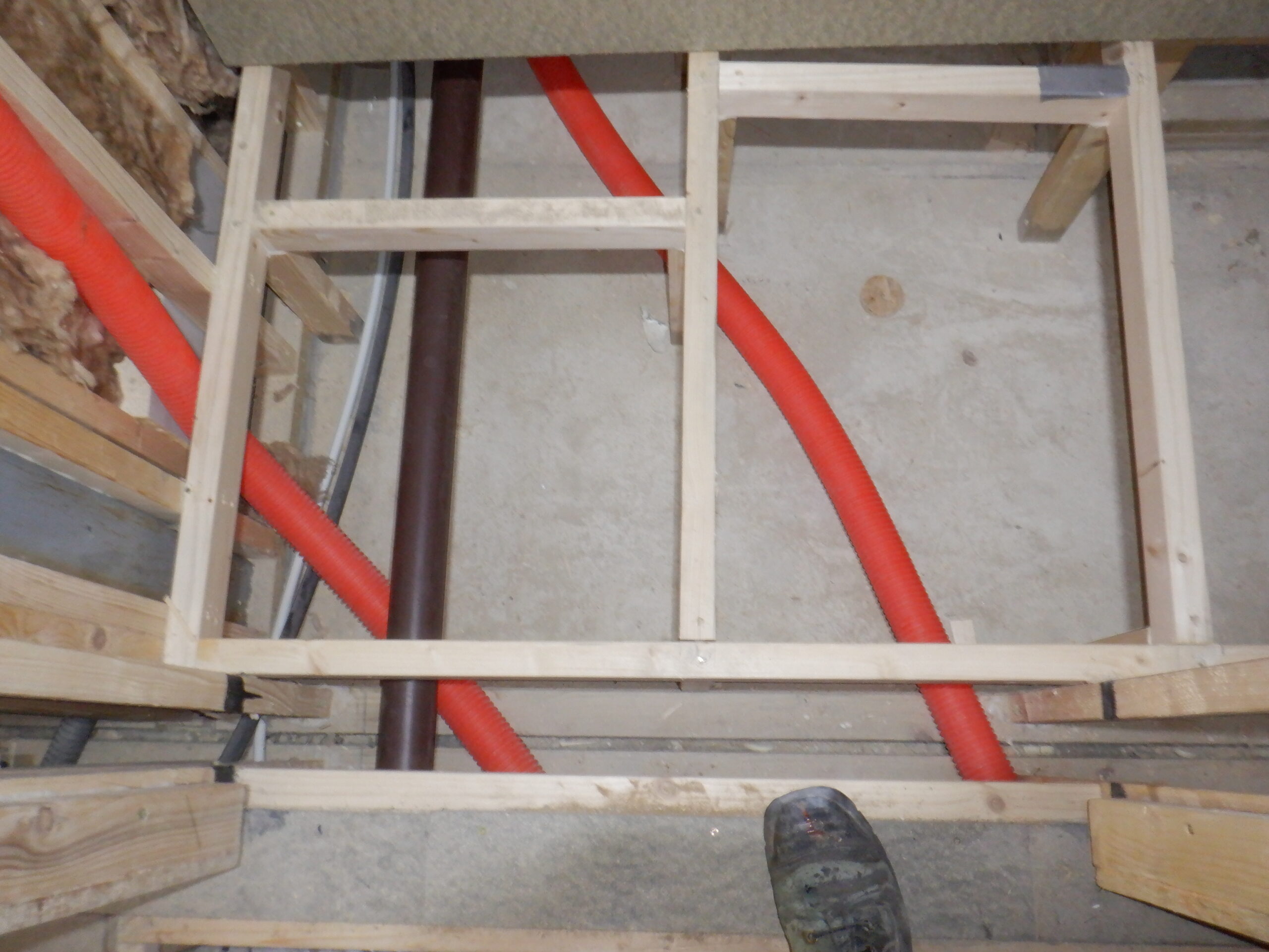
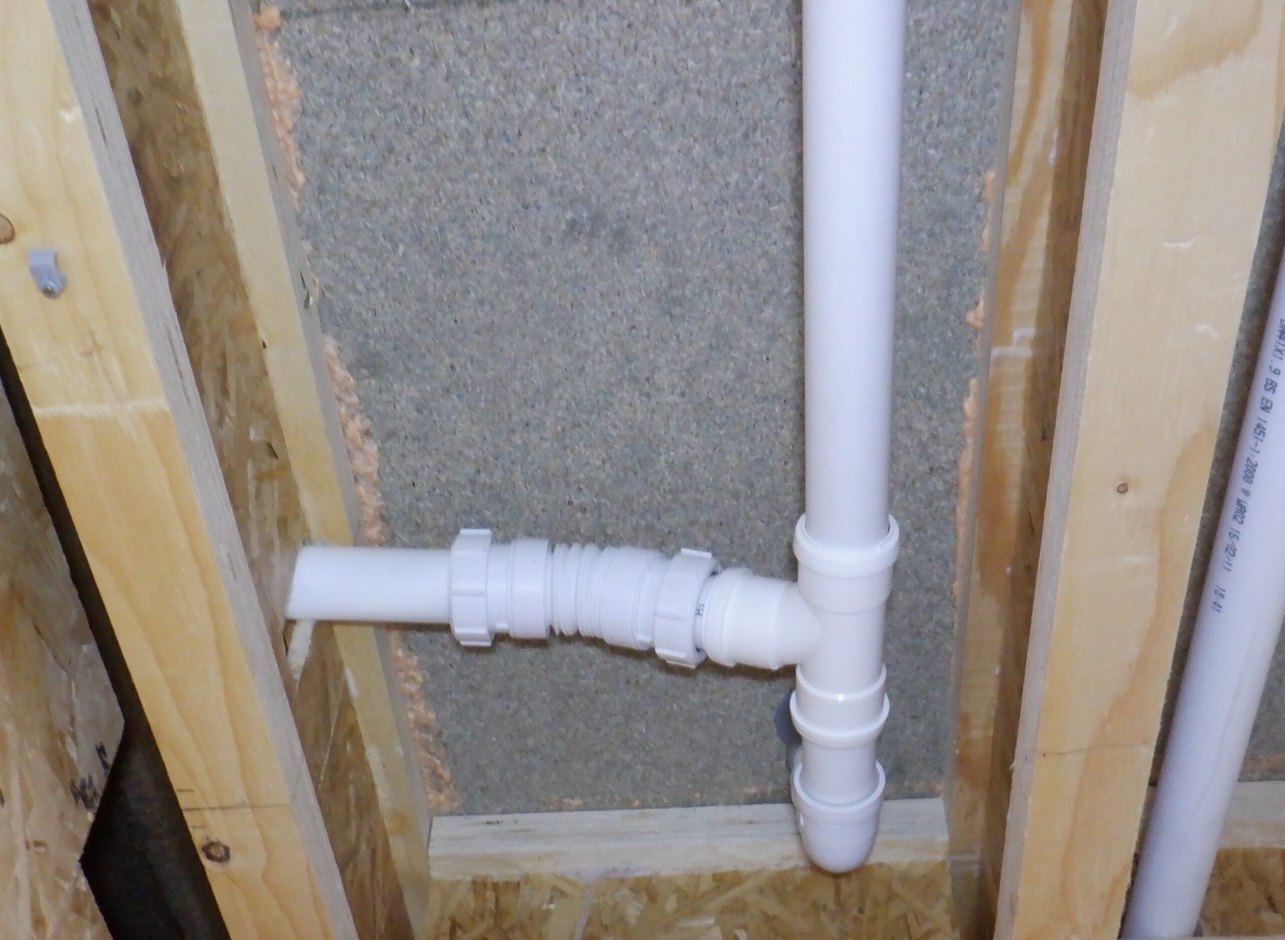
Also on this Header Tank, is an overflow emergency drain point, right at the top, to make sure that if something goes wrong with the automatic mechanisms, the water will have somewhere to escape and not flood the the upstairs flooring, and drip downstairs into the Bathroom and Bedroom Two. This 40mm diameter “push-fit” white plastic pipework goes down from the tank connection at the back right hand corner, through the floorboard and then turns at an angle to pass through the webbing of the First Floor Joist, to arrive at the drain line that is coming from the Shower Room. We had to use a “flexible fan-folded” pipe to achieve the awkward angle but we managed to join into the pipe, which then goes into a Hepworth Valve (these are non-return rubber valve designed for waste water from bathroom basins and showers, these valves are to stop the horrible smells coming up the septic processing pipes) and this line of 40mm pipe then turns the corner and goes through another webbing of the joist and connects to another branch line that is coming from the sink that will be in the upstairs work room.
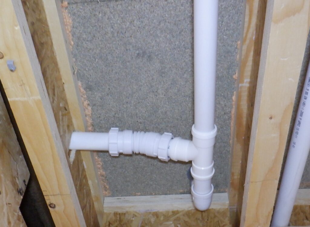
Header tank overflow
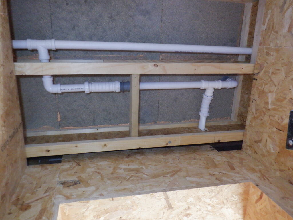
Header tank Overflow and Shower connections
The new rainwater pump came today and we swopped over the two pumps. We discovered that the older pump wasn’t sitting as deep inside the rainwater tank, due to the automatic cut-off float switch that is attached on the side of the pump and it made the pump a bit wider and it was jamming at the bottom of the manhole column. So, when we lowered the new pump, it went further down and we discovered that the semi-flexible pipe, the vertical pipe that takes the output of the pump up to the top, was not long enough to reach the right angle connector. We had to extend this vertical part by another 200mm! Fortunately, we could use a spare piece of our 32mm blue pipe and replace the right angle connector with a full sized 32mm version instead, which made it more reliable and neater. We got it all sealed and tightened down and connected up the electricity again, and reran the tests we did earlier. So, the results of upgrading the pump, we achieved a thirteen fold increase in flow rate. The flow sensor went from 6.5Hz to 85Hz! This is so much better and we were pleased. Now, putting in the two filters this time, and the water flow rates came down a little bit, to a meter reading of 65Hz, which translates to around 8litres per minute. Interestingly the fine filter started getting brown almost immediately showing that the ‘clear’ water was anything but. We can live with that and one of the reasons for having such a large Header Tank, was that we could serve people having several showers, lasting 15 to 20 minutes each, which an estimated uses of about 100litres per person, assuming two or three short blast of water, at a rate of 15litres per minute and lasting a couple of minutes or so. With the tank holding 500litres of water, it doesn’t matter that we can only refill at 6litres per minutes and besides, it probably be able to catch up between those short blasts!!
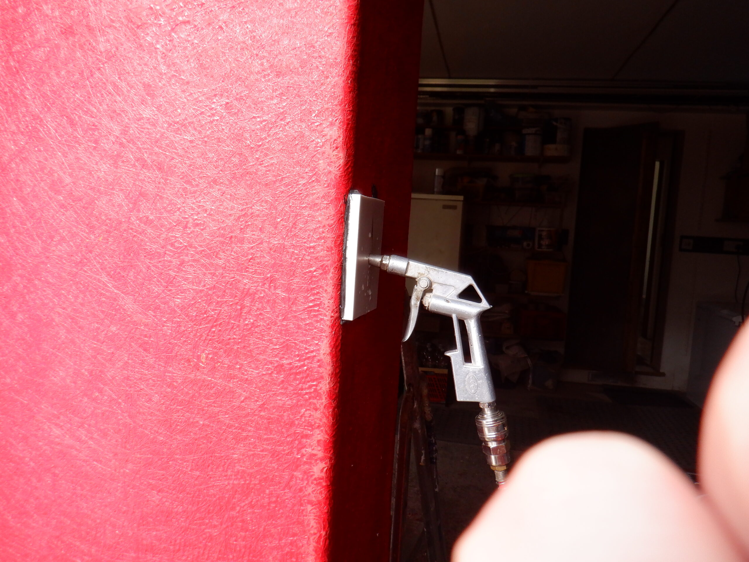
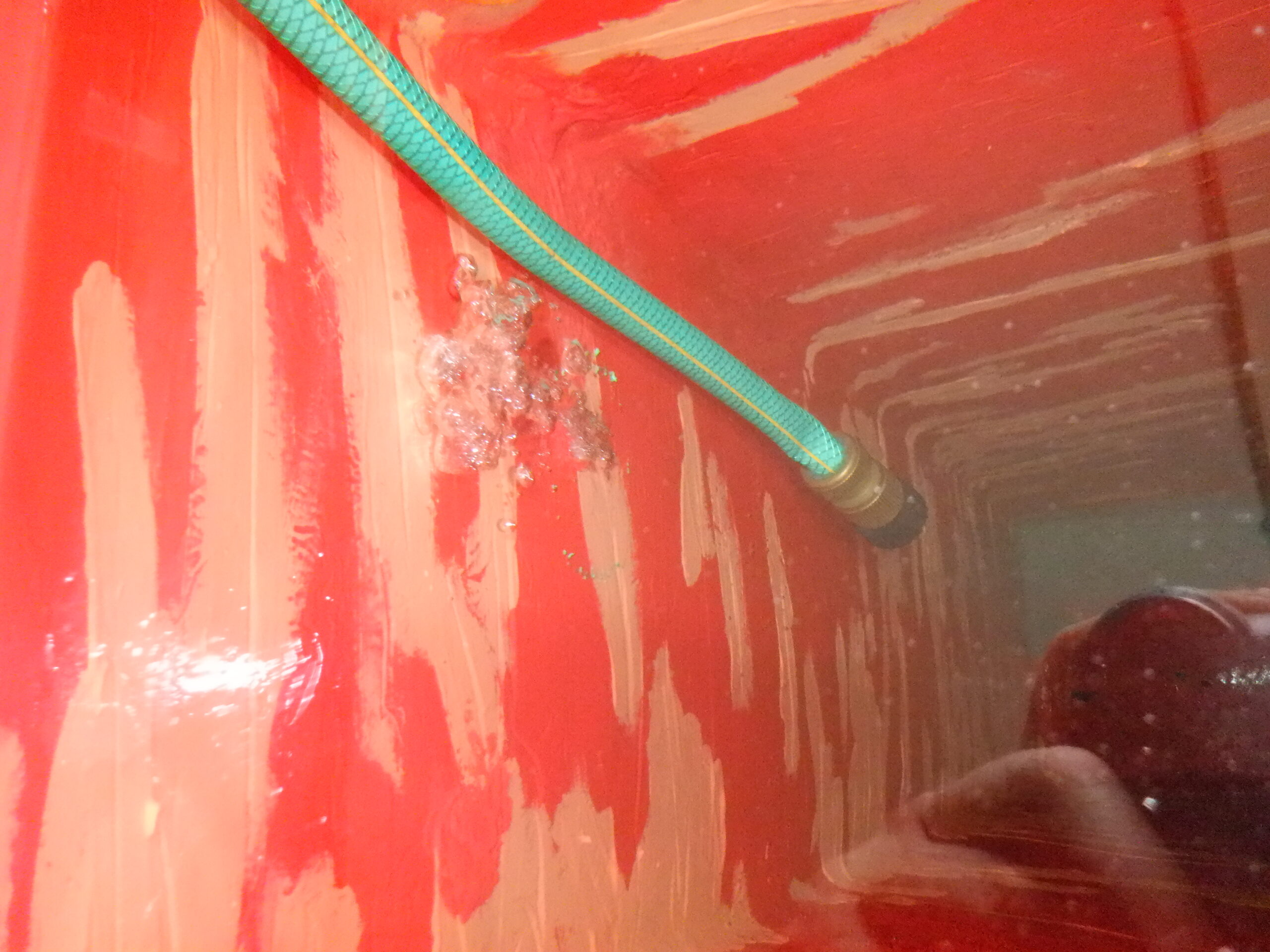
The final job to do, is to do a leak test on all our fittings. We did this by putting in a reasonable amount of water into the Header Tank and connect up the controller to the new Cold Water pump and pressurise the whole system. But, before we switched on the pump, we discovered that the head pressure was efficient enough to open the non-return valve so we could fill the whole circuit up with water, all the way to the end point in the Kitchen. We attached a short length of 22mm pipe to our manual shut-off valve in the Kitchen and direct the other end in a large trug. Once we had water coming through, we turn the shut-off valve to isolate the flow again, and went around looking and feeling for any leaks. At this point, we estimate that these fittings are being stressed at a gentle half an atmosphere of pressure, just from the height of the water in our Header Tank alone. We discovered one leak in our Utility Cupboard end, the flexible pipe coming from the pump to the shut-off valve so we redid the joint again and make sure it was nice and tight this time. this delay then allow us to discover that all our shut-off valve that hang off all T-junctions were weeping a tiny amount of water, including the last one in the Kitchen. There are eight of these side branches in total and only one of them, the one under the sink in the Utility Room had no signs of moisture. This meant that we had to drain the entire pipework of its water, by connecting a length of garden hose (running it out the door to our garden) to our specially installed drain tap. We ought to had used a pump to suck out the water, but we had the good idea of using our compressed air to push the water out quick, by putting the air nozzle into the Kitchen pipe. The only problem was that it was too FAST and the garden hose flew off the little barbed connector and we had a blast of water and air sizzling out! We hastily turned off the drain tap and began mopping up about two litres of water in the bottom of our Utility Cupboard. Fortunately, we had designed the cupboard to be water tight as possible, using bitumen sealant under the CLS footplate of the cupboard walls and also used preservative treated timber as well. After we tidied up, and finish emptying the rest of the water, we went around the seven locations; Bedroom Three, Hallway outside Bathroom, Bedroom Two, Bedroom One, two of them in the Great Room and the last one in the Kitchen. We had originally put on PTFE tape plus LSX but it wasn’t quite enough so we undid the joint and wound on a couple more turns of the PFE tape and extra LSX sealant and screwed it back on. We left them to cure and dry overnight before resuming testing again on the following morning.
The following morning revealed that we had fixed those leaks, and under maximum pressure, when the pump is running, we solved those leaks for sure. BUT .. we had another very slight leak at the side branch inside the Utility Cupboard. It is a similar connection combination so we had to drain the pipework again, which turns out not to be very satisfactory. The drain valve is a clumsy design and when we undo the valve, it leaks all over the place. we shrugged our shoulders as it is not going to be often, to be draining the system and doing maintenance work. We fixed the leak in our tap-off branch (to supply water to various destinations inside our Utility Cupboard) and got it back up and pressurised again. We did have to run our rainwater pump, to put more water into our Header Tank so we could carry on with our testing work.
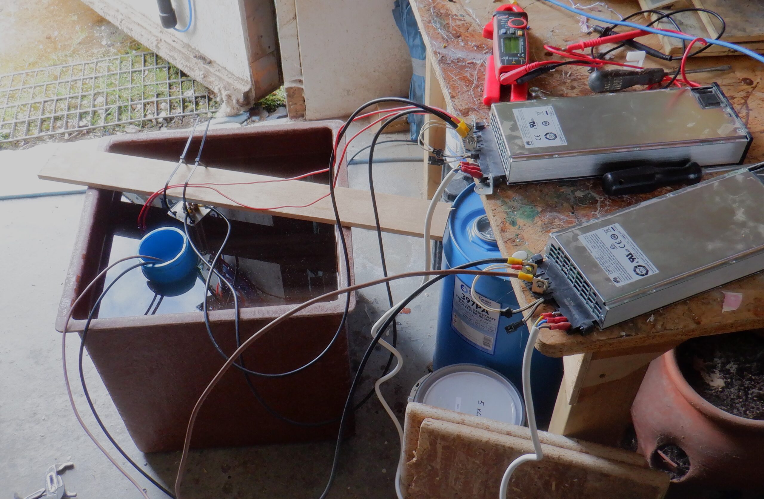
We also brought out our electronic measuring devices and hooked it up to both the pressure meter and the flow rate meter sensors, they produce an electrical signal and we used two multi-meters to take a reading in tandem. The Pressure sensor produces a voltage between 0.5V and 4.5V, representing 0pascals and 500,000pascals respectively. That is approximately Zero atmosphere of pressure (just open to the air) and Five times the atmosphere of pressure. Our pump can manage three atmosphere of pressure, i.e. 3bars so our sensor can cope just fine.
The flow rate is similar to the one we have used for the Header Tank upstairs, but it is a bigger affair so the formula is slightly difference. We measure the pulses it generates and then we divide that numerical value by the “adjustor value” which is 1.08 this time, and this calculation gives us litres per minute. So, what are the readings I hear you ask? Well, without turning on the pump, the pressure sensor gives a value of 1V which works out to be just over half a bar of pressure, which is what we would expect considering that the header tank and its water level (the tank is only half full) is about 5metres above ground level and that means half an atmosphere of pressure. The flow rate values that were recorded on the multi-meter was 14Hz so after putting that through the formula, we get a value of 13litres per minutes. That is not bad at all, just for a Header Tank by itself!
So, after switching on the pump, we got a different set of readings, naturally enough. They were 2.8V for the pressure, which translates to 2.8bars of pressure (a bit of a coincidence) and a flow pulse rate of 35Hz, which translates to 32.5litres per minutes. The pressure is looking good but the flow rate is a bit slow. That is odd (Is the pump running backwards?).
Now, we can turn off the Kitchen shut-off valve and build up the pressure in our expansion vessel, which takes a few seconds and then we turned off the motor. At this point, we go around and check all our connections everywhere again, now that we have pressurised the Cold Water system. The Great Room is ok, Kitchen is OK, Bedroom One & Two & Three are ok, the Bathroom is ok and the Utility Room is ok too. BUT .. we got another leak! This time, our pesky “bless-its-heart” drain cock is weeping drops of water! O Boy!
This is the last straw for that poor drain point!! It had to go! So, We found another shut-off valve with a three quarter inch male thread so it could screw directly into the T-junction and on the other half, put an adapter to allow for a quick fitting hose connector so we could just plug in the garden hose and drain it outside somewhere. Perhaps later on, we may provide a drain standing pipe inside the Utility Cupboard, with a U bend trap (to stop the smells) so if we need to drain any water in any of our other pipework, we only have a short distance to stick the hose down and release the water.
So, off we go again .. we filled up the pipework up (we had a very large trug in the kitchen to allow us to clear the whole pipework of any air etc. .. we had to be very careful to haul this trug of water outside! Twice!) and pressurised the system again. We took a reading off the pressure sensor (measuring 2.775Volts) and leave it for a while to see if the pressure holds .. or not!
Barring any further leaks .. from our pressure test .. this concludes this particular job! We now have a Cold Water system to serve the House, the Garage and the Garden (eventually) – Phew!!